A field test demonstrated the ESP shuttle system’s ease of retrieval compared with conventional downhole pump installations.
Frank Ingham, RMOTC
Electric submersible pumps (ESPs) are a versatile means of artificial lift used in oil and water wells. A drawback to an ESP installation is that it is a complex operation with considerable equipment, personnel and time required. When a remove/repair/replace operation is necessary, the same considerations are required. The conventional methodology requires a service rig and crew to pull and re-install the tubing; a cable spooler for the electric cable; and banding personnel and equipment. In addition to the time and expense, there are safety and risk issues associated with handling the tubing and cable.
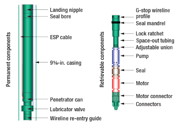
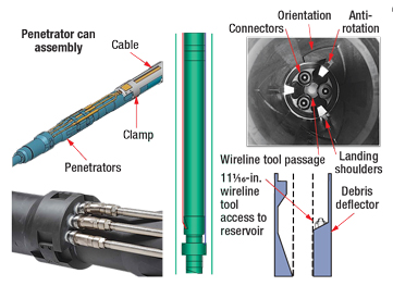
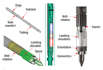
Zeitecs Inc. developed a technology consisting of a permanent component installed at the bottom of the tubing and a retrievable component. The pump, seal and motor of the ESP are combined with an electrical docking and mechanical locking system to form an ESP shuttle that can be retrieved and re-installed through the tubing by wireline, Figs. 1–3.
 |
|
Fig. 1. ESP shuttle system design.
|
|
 |
|
Fig. 2. The permanent components are attached to the bottom of the tubing on initial installation. The electrical cable is installed as part of the permanent components and is connected to control equipment at the surface.
|
|
 |
|
Fig. 3. The retrievable components, which include the pump and motor along with electrical connectors, docking and lock-down mechanisms, form a shuttle that is installed last with a wireline. The shuttle can be installed, retrieved and re-installed through the tubing.
|
|
The company and the Rocky Mountain Oilfield Testing Center (RMOTC) jointly tested the new technology at RMOTC’s test site at the Teapot Dome oil field 35 mi north of Casper, Wyoming. The ESP shuttle system was deployed in a well using an RMOTC workover rig and crew, along with Zeitecs and Wood Group equipment and personnel. The ESP was turned on, pumped for a period of time and then turned off. A wireline unit was used to lower a latching mechanism through the tubing and retrieve the pump. A series of 15 “make and break” tests of the electrical connection over the testing period (about two weeks) verified the durability of the wet mateable connection. The pump was retrieved to the surface and then lowered back down the tubing, where it was docked and returned to pumping. A complete retrieve-and-re-install operation was demonstrated in 2 hr and 40 min.
Data and operational notes were obtained to be used for refinement of the system. The test was successful enough to repeat the procedure the following week as a field demonstration for clients.
INTRODUCTION
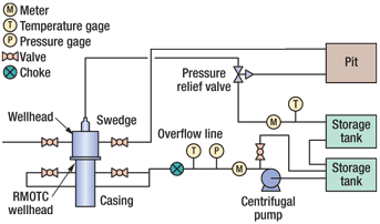
The ESP shuttle system was built to be deployed on 7-in. tubing and required a well with a minimum flow capacity of 1,500 bbl of fluid per day. RMOTC had a borehole with 95⁄8-in. casing, the minimum size that could be used, but no wells with both the required flow capacity and the required casing size. In the 61-2-TpX-15 well, the 95⁄8-in. cased hole had been plugged back to 2,895 ft and had no perforations. It was essentially a large test tube. It was proposed that a closed-loop flow system be built so that the ESP could pump water from the borehole to a storage tank, from which it could be pumped with a surface pump down the backside of the well and circulated continuously as required, Fig. 4.
|

|
|
Fig. 4. Water is pumped by the ESP up the tubing and into the storage tanks which are equalized by flex hoses connected near the bottom of the tanks. The centrifugal pump pumps water from the tanks through a choke valve and down the casing-tubing annulus, where it could be recirculated as desired. A pressure relief valve was connected to a chained-down hard line that would divert to the pit. A tee and valve would allow diversion of the centrifugal pump output to the storage tank if necessary.
|
|
TEST PROCEDURE
Preparation for the test began in June 2009. The tubing was to be 7-in.-OD flush-joint 26# P110 Hyd 521. Because of the small annular space between the 7-in. tubing and the 95⁄8-in. casing, and the need for an electrical cable and sufficient volumes of water to pass through, a bit and scraper were run and water was circulated to the pit to ensure that the casing was clean. The bottom was tagged at 2,895 ft, and the well was pressured to 500 psi for 15 min. to test the integrity of the casing and plug.
Two 2-in. full-port ball valves were installed on each side of the existing Larkin wellhead. The cap was removed, and an RMOTC-supplied, screw-on, 3,000-psi adapter was installed to allow a wellhead to be attached to the well. A flow system was plumbed to facilitate circulation from the tubing side of the wellhead to the tanks and down the back side of the well. Flowmeters, pressure gauges and temperature gauges were installed.
The 7-in. tubing was sent to the field, and a local company performed a clean-and-drift job. A wellhead was delivered to the site and installed. Trailer-mounted transformer/variable-frequency-drive (VFD) equipment was sent to be connected to an RMOTC generator and tested prior to the installation of the ESP shuttle.
Field testing began on July 13, 2009. There was a delay when it was decided, as a precaution, that the penetrator can assembly that would go on the bottom of the tubing string would be made up in Casper rather than at the test site. (Subsequent refinements have obviated the need for this consideration.) By afternoon, the bottom joint of tubing with the penetrator can assembly was picked up, and the slotted screen was attached. The cable was spliced to the docking assembly pigtail and banded as the first joint was lowered into the hole. This assembly was left hanging in the slips and elevators overnight.
The following day, the remaining tubing, cable and banding was installed to a depth of 2,385 ft. The cable connections were made beneath the tubing hanger to the harness that fed through the tubing hanger, and the hanger was lowered into position and bolted into place. The casing crew was loaded out, and the workover rig was rigged down and moved off. The junction box was installed and the connections made to the surface cable. The site was then shut down for the night.
The following morning, the RMOTC well pump hoist was moved in to perform as a crane. The ESP shuttle components (connector, motor, seal, pump and lock-ratchet assembly) were picked up individually, assembled sequentially and lowered downhole until the top of the assembly was landed on the wellhead. The sheave for the wireline unit was then hung from the hook of the crane and raised over the wellhead. A wireline jar assembly was attached to the top of the shuttle assembly, and the shuttle was lowered to the bottom and docked. The wireline jars were used to jar down to release the latching tool and then were pulled out of hole.
A switchboard was moved into place and the electrical connections made. The ESP and surface pump were turned on and circulation began. Initial flowrates were 3,250 bwpd from the ESP to the tanks and 2,850 bwpd pumped from the tanks and down the back side of the well. Pressures on the backside system through a single backside valve were:
• Pump outlet—165 psi
• Inflow side of flowmeter—145 psi
• Outflow side of flowmeter—87 psi.
The choke was set at 65%.
In addition to the surface gauges, downhole gauges are installed with the permanent components of the shuttle system to monitor pump intake pressure and downhole temperature.
Circulation continued for approximately one hour before the pumps were turned off. The wireline was used to unseat the pump. After several cycles of seat/unseat and electrical measurements, personnel were satisfied that the system was working correctly and the site was shut down for the night.
The next morning, the shuttle was pulled out of the hole via wireline. Considerable debris was found while disassembling the components; the debris appeared to be iron flakes from the tubing or casing. Further investigation revealed that the tubing had been used before being deployed for this test. The cleaning crew that had cleaned and drifted the tubing two to three weeks earlier had not been able to remove all the debris. An RMOTC water-pressure truck was brought in and circulated clean water down the back side while the tubing side was flowed to the reserve pit. After some initial discoloration, the flow cleared up and no more debris was found. The shuttle equipment was cleaned and flushed. The pump was cleaned and reassembled. The equipment was reinstalled and tested successfully. The site was shut down for the weekend. Overall, the test was deemed successful.
On Monday morning, operations continued. Zeitecs had clients on location to observe a demonstration. The pumps were turned on and pumped/circulated for a period of time. The pumps were then turned off, and the wireline unit was used to unlatch the shuttle system. The ability to make and break electrical connections was demonstrated, and the system was pulled out of the hole. The lock-ratchet assembly was redressed, and the shuttle was run back in the hole and redeployed. The demonstration was successfully concluded by mid-day.
RESULTS AND CONCLUSIONS
The ESP shuttle system proved robust in an operating environment and performed as desired. Throughout installation and two retrieval/reinstall cycles, refinement details were learned but no major failures occurred. This was the first time such a system had been successfully deployed in the US and only the second time worldwide. Zeitecs subsequently deployed the system in commercial operations.
The demonstration indicates that the potential benefits of this technology are many. There are the obvious time and cost savings when an ESP requires maintenance. There also is less downtime and associated loss of production revenue. Other benefits include changes in ESP management paradigms. In case of suspected ESP problems, the operator no longer has to weigh the costs of suboptimal performance and uncertainty against the high costs of a pulling operation. Preventive maintenance can be performed more economically, therefore extending the life of equipment. If reservoir performance is changing rapidly, the ESP can be optimized for different stages rather than installing a best estimate averaged over the expected lifetime between pulling operations. Where rig scheduling and access are issues, the technology may be the only option for timely intervention for ESP problems. 
ACKNOWLEDGMENTS
The success of this field test was attributable to the professionalism, resourcefulness and coordination of many people and their companies. In particular, the author recognizes the contributions of Everett Walker, RMOTC field coordinator; the workover rig and pump hoist operator, Art Paulson, and his crew Thomas Platt, Justin Tonsfeldt and Jared Baker; Steve Griswold of Frank’s Westates Services; and the personnel with Zeitecs and the Wood Group.
|
THE AUTHOR
|
 |
Frank Ingham has over 30 years of industry experience with expertise in interpretation and analysis of subsurface geologic, geophysical and reservoir data. Prior to joining RMOTC, Mr. Ingham worked for Hawthorn Oil Co., Gulf/Chevron and Shell. He holds a BS degree in electrical engineering from New Mexico State University and has completed coursework in petroleum technology, drilling, geology and hydrogeology.
|
| |
| |
|
|


