Applied downhole, this geophysical tool—already established in surface applications—could provide deeper depth of investigation than traditional nuclear measurements.
Francis Neill, Gravitec Downhole Instruments
Gravity gradiometry has been rapidly gaining acceptance as an additional tool in the geophysical toolbox when deployed in either aircraft or ships. The potential for its use for downhole applications including reservoir monitoring has been identified for some time. However, the sensors used for surface applications are unsuitable for downhole applications, so little investigation has been carried out on wellbore applications. This article discusses the potential application of the technology as an ultradeep-reading density measurement for reservoir monitoring, and presents the principles and design of a ribbon gravity gradiometer suitable for downhole deployment.
INTRODUCTION
Gravity gradiometry, a measure of differential acceleration of the Earth’s gravity field over a unit distance, is not new to the oil and gas industry. The first geophysical survey used in oil exploration was a gravity gradiometry survey. In 1915, a torsion balance was used to survey the Egbell oil field in Slovakia by the D’Arcy Exploration Company, an affiliate of the Anglo-Iranian Oil Company, which later became BP. The results were highly successful but, due to World War I, it was 1924 before the technique was successfully used in the US, to discover the Nash dome in Brazoria County, Texas. From then until 1936, gravity gradiometry surveys using torsion balance equipment were used extensively in exploration.
The torsion balances used for these early oil exploration activities were Eötvös balances, designed by Baron Loránd von Eötvös, a Hungarian physicist who is remembered today for his experimental work on gravity, in particular his study of the equivalence of gravitational and inertial mass (the so-called weak equivalence principle) and his study of the gravitational gradient on the Earth’s surface.
The difference between gravity and gravity gradiometry is subtle but important. A traditional gravity tool or gravimeter will measure the z component of the gravity vector g (gz). This is massively dominated by the earth’s gravity field. A gravity gradiometer, on the other hand, will measure the derivative of the components of the gravity vector g (gx, gy, gz) in three orthogonal directions of space (x, y, z). These derivatives are the components of the gravity gradient tensor, which is denoted by:

Only five of the nine components are independent. Where five simultaneous measurements are made, the sensor is known as a full-tensor gravity gradiometer.
The unit of gravity gradient used today is the Eötvös (E), a unit of acceleration divided by distance that is defined as one-billionth of a galileo per cm. The galileo is a unit of acceleration equal to 1 cm/s2.
Over the last 10 years, gravity gradiometry has seen a resurgence of interest in the oil and gas industry, and the technology is becoming widely adopted by geophysicists. Modern technology and advanced processing have enabled airborne and seaborne systems to provide levels of detail in subsurface mapping that traditional gravity surveys cannot deliver.
GRAVITY AS A POTENTIAL SUBSURFACE TOOL
Gravity has been long identified as a possible tool for monitoring fluid changes within a reservoir. Surface gravity has been used by BP in Alaska with excellent results for waterflood surveillance. Statoil has also used seafloor gravimeters extensively on the Troll gas field with considerable success. However, both of these scenarios represent near optimal conditions for surface gravity, and, without an increase in resolution of sensors plus better noise isolation systems, surface gravity reservoir monitoring applications will be constrained by the depths of the reservoirs and the need for a significant difference in fluid densities. Placing the sensor closer to the zone of interest, in the well, is an obvious way to overcome depth-of-investigation limitations. A sensor that can resolve a density change 500 m from the sensor will have a much wider application when placed downhole than at surface.
Borehole gravity meters (BHGMs) have been used since the 1970s as deep-reading density tools. Near-wellbore effects such as rugosity and invasion have very limited impact on BHGMs, whereas they greatly affect traditional, nuclear-based density tools. However, while providing interesting data, downhole gravity meters have never become widely used. This has been due to a range of factors:
• Only a limited number have ever been built.
• The maximum deviation was limited to 15°.
• The smallest OD was 4⅛ in., restricting borehole size.
• Stationary readings are taken with time intervals lasting up to 10 min.
• The required accuracy of depth control between stations has meant that stations needed to be far apart in order to reduce inaccuracies.
The result was that, while seen as an interesting technology, borehole gravity measurements have never acquired widespread acceptance.
APPLICATIONS IN RESERVOIR MONITORING
The need for a technology that can “see” deep into the reservoir has long been identified. Four-dimensional seismic was developed as one solution to this challenge. However, 4D seismic is expensive, does not work in all conditions and provides limited resolution at reservoir level. Traditional pulsed-neutron tools used for saturation monitoring have a depth of investigation of a few centimeters. Cased-hole resistivity tools increase this depth of investigation to a few meters in optimal conditions. Deep electromagnetic sensors have potential, but the measurements are sensitive to multiple downhole parameters.
Two factors are critical for any “early warning” reservoir monitoring tool: depth of investigation and directional ability. On average, a water front moves through a reservoir at about 1 ft (30 cm) per day. A tool that could detect an approaching water front at 30 m from the borehole would give 3 months’ notice of its arrival. If this is increased to 100 m, that would give 10 to 11 months’ prior notice of water breakthrough. A 500-m depth of investigation provides nearly 5 years’ warning.
However, not all reservoir applications require a large depth of investigation. In vertical or deviated wells, water or gas coning can impact shallow-reading cased-hole logs; as a result, determining the true water or gas contacts may be difficult with traditional logs. A gravity gradiometer could see beyond the coning and provide the true contact depth in the reservoir.
In a horizontal well, a gravity gradiometer could see downward gas coning or upward water coning as it happens. An array of permanently installed gravity gradiometers could make the intelligent well a reality. The effects of altering production rates, choking zones back with inflow control devices or shutting off zones could be monitored in real time.
Directional measurement is also critical. For example, in heavily compartmentalized fields where reservoir structure is poorly understood, just the ability to monitor in which direction saturation changes are occurring would add valuable data and understanding of the subsurface structure.
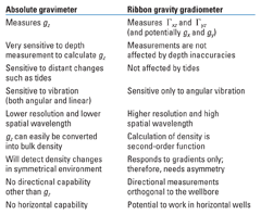
Both gravimeters and gravity gradiometers have reservoir monitoring applications. The advantages and disadvantages of both are outlined in Table 1.
| TABLE 1. Advantages and disadvantages for reservoir monitoring |
 |
THE RIBBON GRAVITY GRADIOMETER
The concept of a string gravity gradiometer was first considered by A. Veryaskin in the early 1990s. Over the subsequent years, the concept evolved from an initial superconducting string sensor cooled by liquid helium into a ribbon sensor that operated at room temperature. In 2006, initial feasibility studies identified that such a sensor was capable of working in downhole environments. The ribbon gravity gradiometer is not a full-tensor gravity gradiometer, but measures the x component of gravity gx varying in the z direction, namely Gzx where the z direction is aligned with the borehole and the x direction is at right angles to the ribbon surface. This allows the sensor to measure directional changes in density orthogonal to the wellbore. In 2007, full development of the sensor for downhole applications was started.
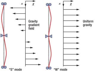
The principle of the ribbon gravity gradiometer is simple. The ribbon sensor is held at either end with a knife-edge constraint in the middle. The knife edges constrain lateral movement but allow rotational movement. When a gravity gradient is applied across the length of the sensor, the ribbon will deflect, Fig. 1. This is known as the “S” mode deflection. When a uniform gravity gradient, such as the earth’s gravity field, is applied to the sensor, it will deflect in the “W” mode.
 |
|
Fig. 1. When a gravity gradient is applied across the length of the sensor, the ribbon will deflect.
|
|
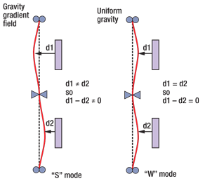
The deflection of the ribbon is measured at two points, d1 and d2, above and below the knife edge, Fig. 2. In S mode, the deflection d1 will be equal and opposite to d2 and subtracting the two deflections will determine the gravity gradient. In W mode, or uniform gravity, deflection at d1 will equal deflection at d2, resulting in a zero measurement. This is known as common mode rejection (CMR). The actual ribbon deflection is a linear sum of the S-mode and W-mode shapes. The differential mode measurement extracts the amplitude of the S-mode, generating a reading of the local gravity gradient.
 |
|
Fig. 2. Deflection of the ribbon is measured at two points, d1 and d2, above and below the knife edge.
|
|
As the deviation of the wellbore increases from zero, the relative component of the Earth’s gravity field will increase to a maximum at 90°. The inherent common mode rejection of the sensor design means that this field will be rejected independent of the deviation, and, therefore, the sensor can work in a range of well deviations from 0 to 90° with no mechanical alterations.
This design has an additional benefit with regard to noise sensitivity. Noise that appears as linear acceleration will behave in the same manner as a uniform gravity field and, therefore, will be rejected by the CMR. Only noise that appears as angular acceleration, a rocking motion, will affect the sensor. High frequency, random angular noise or white noise can be time-averaged out, meaning that the only noise left that the sensor is materially impacted by is low-frequency, or sub-1-Hz, angular noise. This low-frequency tilt noise can be mitigated by suitable isolation systems within the downhole tool.
The sensor also uses a second order of differential measurement to further minimize the effects of thermal changes and other effects. The ribbon tension is modulated between two values, creating a “stiff” and “soft” mode. Because environmental effects will impact both modes equally, they will be eliminated using the differential measurement between the two tensions.
Thanks to the long, thin design, unlike traditional surface gravity gradiometers, the ribbon gravity gradiometer is well suited to borehole applications, Fig. 3. In its existing form, the sensor measures 40 cm long with a 4-cm cross-section. The fundamental design of the ribbon sensor allows further reduction of the cross-section if required.
 |
|
Fig. 3. The sensor’s long, thin design is well-suited to borehole applications.
|
|
DEPLOYMENT METHODS
The gravity gradiometer sensor has the potential to be deployed either as an intervention tool on electric line or as part of the completion as a permanent sensor. Due to the ribbon’s directional capability, it is advantageous to rotate the sensor to obtain a 360° image orthogonal to the wellbore. Due to the principles of the ribbon and fundamentals of gravity, the sensor does not see a pinpoint image at any specific angle, but rather looks at a 60° “cake slice” of the formation.
RESERVOIR PARAMETERS
Like most downhole measurements, a stand-alone gravity gradiometry measurement in Eötvös will not give a unique answer in subsurface parameters. Additional input or constraints are required to achieve a unique solution.
However, the equations of gravity are, unlike nuclear or electrical measurements, not affected by the environment. There are no correction factors.
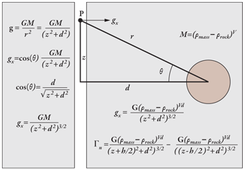
The gravitational force gx due a volume V with a density þmass , surrounded by rock of density þrock, is a function of the square of the distance the volume is from the sensor. As shown in Fig. 4, at any point in the wellbore:

where G is the universal gravitational constant, d is the perpendicular distance to the center of the volume, and z is the vertical distance along the wellbore of the sensor from the center of the volume. The gravity gradient at that point in the wellbore due to the volume V is then:

where h is the sensor baseline length. With this single equation, one can then forward model the gravity gradient in the wellbore for any subsurface scenario by populating a 3D model with densities.
 |
|
Fig. 4. Equations for the gravitational force and gravity gradient of a volume detected by a sensor in the wellbore.
|
|
The gravity gx and the gravity gradient Gzx versus depth are as shown in Fig. 5.
 |
|
Fig. 5. a) Gravity gx versus depth. b) Gravity gradient Gzx versus depth.
|
|
NEAR-WELLBORE EFFECTS
Due to the relatively low volume of near-wellbore events, they have a limited impact on the overall gravity gradient signal. For example, when deployed on an electric-line tool and centralized in the middle of the wellbore, casing collars and tubing joints will create no gravitational gradient, as they will be fully symmetrical with the sensor. Formation wash-out has the potential to create gravity gradients; however, modeling has shown that, for standard class-G cements, this signal will be typically less than 1 E. In some cases where there is a large density difference between the cement and the formation, it may be larger than 1 E.
FAR FIELD
The market acceptance of gravity gradiometry will depend to a large degree on the depth of investigation that can be achieved. This will be dependent on the sensor resolution. The sensor resolution is defined in E/√Hz. Where the downhole noise is white or random noise greater than 1 Hz (which it is expected to be), time averaging can be used to improve the resolution of the sensor. This will achieve the actual resolutions shown in Table 2.
| TABLE 2. Actual resolutions |
 |
The density change due to changing fluids will be a factor of:
• Density difference between the two fluids
• Porosity
• Saturation changes.
Where the density difference between the two fluids is large, the change in the gravity gradient will be correspondingly large. Thus, a saturation change from gas to water will create a larger gravitational gradient change than a change from oil to water.
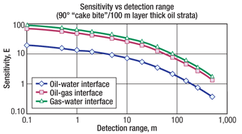
Figure 6 shows the sensor resolution in E versus the detection range for a saturation change. The diagram assumes a 90°, “cake bite” model, with a uniform 100-m thick stratum.
 |
|
Fig. 6. Sensor resolution versus the detection range for a saturation change.
|
|
From the figure, one can see that a wireline-deployed sensor with a resolution of 2 E would have a detection range on the order of 100 m for an oil-water interface and on the order of 400 m for an oil-gas interface. A permanently installed sensor, which could achieve resolutions on the order of 0.2 E, could detect a gas interface at 1 km from the wellbore.
In many situations, such a large depth of investigation will not be necessary. As stated previously, in a typical reservoir a depth of investigation of 30 m will provide 90 days’ notice prior to a water or gas front reaching the wellbore. In some cases, just being able to determine the gas contact by measuring beyond coning would add value to reservoir management. In horizontal wells, a detection range of 10 m could be used to manage inflow control devices to prevent coning of water upward or gas downward.
CONCLUSIONS
Downhole gravity gradiometry has the potential to be a new tool in the reservoir management toolbox. A sensor that can detect changes in density in a directional manner, tens or hundreds of meters or even 1 km from the wellbore, will provide reservoir engineers with a new means of actively managing their reservoirs.
Existing gravity gradiometers are large, expensive and unsuitable for downhole applications. The ribbon gravity gradiometer is well-suited to downhole applications thanks to its simplicity and shape. While challenges remain in understanding and mitigating the wellbore noise regime and handling the thermal gradients inherent in a wireline-deployed tool, the new sensor has potential in a wide range of reservoir monitoring applications. 
|
THE AUTHOR
|
| |
Francis Neill, Chief Executive Officer of Gravitec Downhole Instruments, can be contacted at francis.neill@gravitec-downhole.com. His career of more than 25 years in oil and gas started with 15 years at Schlumberger, followed by time with Aker Subsea and Expro. For the past three years, Mr. Neill has been involved in technology startups in both well intervention and subsea.
|
| |
| |
|
|


