Testing of a prototype sand screen with a surface-operated back-flush mechanism found that the tool efficiently and reliably removed sediment, allowing uninterrupted fluid inflow to the wellbore.
Robert Gordon, Global Oil Filter; and Mike Curtis, RMOTC
At the beginning of June 2009, Global Oil Filter Inc., together with the Rocky Mountain Oilfield Testing Center (RMOTC), performed a test on a prototype downhole self-cleaning screen tool. The scope of the test was to evaluate 1) the performance of the screen in oil, 2) the performance of the back-flush mechanism in oil, and 3) the cleaning efficiency of the unit in oil.
The tests demonstrated effective and reliable operation of the screen and back-flush mechanisms when activated with air. In the test configuration used, a production rate of greater than 20 gallons per minute (gpm) was measured, and a very high cleaning efficiency of the screen was observed. The success of these tests show that the self-cleaning screen tool is ready to be field tested in a producing oil well.
INTRODUCTION
Sanding is a significant problem in many oil and gas wells because produced sand can abrade and damage the well infrastructure and progressively reduce well performance. Sand screens are commonly used to stop free sand particles from entering the well, but a shortcoming of the passive sand screens currently available is that they can eventually become blocked. As this occurs, production decreases and economic value is lost. Remediation is costly because returning the well to optimal performance requires that the production string, downhole pump and sand screen be removed so the screen can be cleaned or replaced. For marginal wells, the cost of remediation can be so high that those wells have to be taken permanently offline and, as a result, that production may be lost forever.
The self-cleaning screen tool resolves the limitations of passive sand screens because, whenever there is an indication that sand is beginning to adhere to the screen, the tool can be cleaned in situ by activating an integrated back-flush and vibrator mechanism. The cleaning process takes less than a minute, with the released sand falling into the rathole of the well.
By activating the tool regularly, operators are relieved of the expense of performing multiple workovers to service a sand screen, and the inflow of fluids remains constant, raising the economic value of the well while increasing total recovery.
Other potential advantages of the self-cleaning sand screen include the following:
• Remediation costs associated with sand ingress from the formation are minimized.
• Remediation costs associated with the ingress of proppant sand are minimized.
• The tool may be activated using formation-compatible fluids.
• The vibration occurring during the cleaning process has the potential to break mineral cake from the screen.
• When activated with steam, the heat may be applied to break down paraffin wax deposits on the screen and in the well and nearby formation.
• When activated with hot or cold fluids, surfactants or solvents may be added.
• When activated with air production operations, output may benefit from the “lift” effect.
The commercial and economic potential of the self-cleaning screen is strong because sanding is a worldwide problem, which occurs notably in fields in Azerbaijan, Angola, Canada, Trinidad, Egypt and the North Sea. In the Lower 48 states of the US alone, perforating and screen technologies are a $200 million/year business, and it has been estimated that sanding is an issue in 100,000 US wells.
TECHNICAL OVERVIEW
The self-cleaning screen unit tested is designed to stop sand grains from entering, blocking and damaging wells and production systems. The technology is protected by a US patent, with other US and international patents pending.
The tool is designed to be deployed on production tubing beneath the downhole pump, and it has a separate supply line to activate the cleaning mechanism. The prototype tested had a 1⅛-in. National Pipe Thread (NPT) male connector to the pump/production tubing and a ⅜-in. NPT male connector for the supply line.
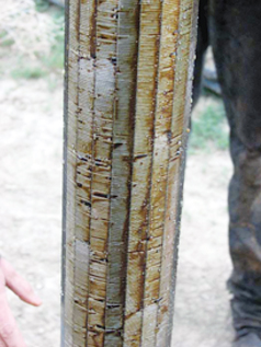
The prototype tested had a 75-micron stainless-steel wedge wire screen of a type currently used in passive sand screen systems, Fig. 1. The mesh was purchased from Leem/LSS Filtration, and other prototypes have been constructed using screen material from Halliburton. The mesh size is customizable, and 25-micron screen materials are commercially available. As fluids enter the well, the screen material physically traps any suspended particles that are larger than the screen size. Those particles are therefore stopped from entering, and ultimately damaging, the well systems.
 |
|
Fig. 1. A close-up of the sand screen after activation and removal from the tank. Oil and water droplets are visible; sand and bentonite have dropped away from the screen.
|
|
The back-flush system is a proprietary, high-energy hydraulic system that dislocates trapped grains from the exterior surface of the sand screen using air, inert gas, water or steam, with or without additives. The configuration of the jets applies a pulsating and spatially consistent force on the entire length and circumference of the interior face of the screen.
A back-flush filter located in the top of the unit stops dirt from entering the back-flush jetting system. This small filter is itself back-flushed whenever the self-cleaning screen is activated.
The vibrator is hydraulically driven to impart energy into both the body of the unit and the surrounding fluids. The vibrations ensure that trapped grains break free and move away from the screen during the cleaning process. The high frequencies achieved can also break mineral cake. Vibration also energizes the fluids in the unit’s immediate vicinity so the freed grains sink rapidly past the unit and into the rathole.
TEST EQUIPMENT
The self-cleaning sand screen was tested at the Rocky Mountain Oilfield Testing Center, a facility operated by the US Department of Energy on Naval Petroleum Reserve No. 3 (NPR-3) north of Casper, Wyoming. RMOTC enables corporations and individuals to test oil and alternate energy technologies in a producing oilfield environment.
Field test equipment was configured to determine and test:
• Methods of activating the back-flush mechanism in oil
• The performance of both the screen and the back-flush mechanism in oil
• The impact of sanding on screen performance
• The efficiency of the cleaning process.
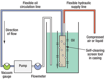
The equipment configuration is shown in Fig. 2. Weather and field conditions on the days of the test varied among cold, mild, windy, rainy and muddy conditions.
 |
|
Fig. 2. The self-cleaning screen was submersed in an oil-filled tank. Oil was pumped through the screen and then returned to the tank. The cleaning mechanism was activated by compressed water or air.
|
|
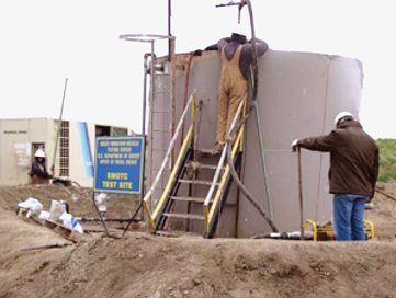
Test tank. The test was performed in the 10-ft-tall production tank at Well 38-SX-3 in the NPR-3 field, Fig. 3. For environmental and safety protection, the tank is surrounded by a permanent retaining berm.
 |
|
Fig. 3. A boom truck was used to lower the self-cleaning screen tool into the test tank. The tool was activated using compressed air and pressurized hot water.
|
|
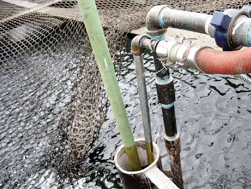
To receive the tool, a 6-ft length of 5½-in.-ID slotted pipe was welded vertically inside the tank positioned about 12 in. from the edge, Fig. 4. The bottom of the pipe was elevated 12 in. above the floor of the tank to ensure that any sand introduced into the casing did not build up around the base of the tool.
 |
|
Fig. 4. To simulate downhole conditions, the tool was deployed inside a length of 5½-in. slotted liner.
|
|
Because the tank had not been used for some time, about eight sacks of bentonite were placed in the bottom and covered with 12 in. of produced water. The water hydrated and swelled the clay to seal the base of the tank against leakage. The tank was then filled to within 12 in. of the top with about 200 bbl of sweet crude oil produced from the Tensleep Formation, Table 1.
| TABLE 1. Physical characteristics of Tensleep oil |
 |
Oil circulation loop. A flow loop was constructed so that the oil could be circulated through the self-cleaning screen unit. The loop consisted partly of flexible hose (to facilitate raising and lowering of the tool) and partly of rigid steel pipe.
In the course of circulating, the oil passed from the oil reserve in the tank, through the slots in the casing, through the screen (which trapped any suspended materials in the oil), and into the body of the unit. Finally, the oil flowed out of the top of the unit and through a length of 1-in. tubing. The oil was then returned to the tank.
To optimize flow, a variety of hose sizes (between 1-in. and 3-in. ID) were tested. However, in all plumbing configurations, the size of the connections to the top of the unit remained constant; e.g., a 1⅛-in. outlet nipple from the unit went through a reducer to the 1-in. tubing. The point of maximum constraint for flow in all test runs was always the 1-in. tubing.
The oil circulation loop also included a pump to circulate the oil, a vacuum gauge so the pressure difference across the inner and outer surfaces of the screen could be measured, and a 2-in. flowmeter.
Circulation pump. For all metered test runs, a gas-powered “trash” pump was used. The pump was able to deliver more than 20 gpm when the self-cleaning screen unit was in the circuit. At the beginning of the test, a compressed-air-powered diaphragm pump was tested. The pump was specified as able to deliver 60 gpm but, as a result of the flow constraint imposed by the 1-in. pipe in the circuit, it was only able to achieve a circulation rate of 14 gpm, which was considered insufficient for the test.
Hydraulic supply line. For all metered test runs, compressed air was used to activate the back-flush mechanism. Hose and compressed air supply configurations that were tested included:
• A Sulaire 140-cu ft/min. (-cfm) compressor, with air delivered through a ⅜-in. hydraulic hose of 1-in. length
• An Ingersol Rand 900-cfm compressor, with air delivered through a 1-in.-long hydraulic hose
• A pressurized water supply from RMOTC’s chemical truck, with air delivered through a 1-in. hydraulic hose.
The back-flush mechanism operated best when high volumes of air were supplied at pressure. The tests were primarily performed using the 900-cfm compressor, which partially vented to the atmosphere so the supplying air could be regulated.
Sand and bentonite. Repeated activation of the back-flush mechanism stirred up and drew up bentonite from the base of the tank, which became suspended in the oil. It was this bentonite that was trapped by the screen during the tests. Bentonite is weathered volcanic ash having a grain size of (nominally) 40 microns. However, when it is saturated, it absorbs water up to five times its own mass to form a gel up to 15 times its dry volume.
Washed sand was introduced into the system only once during the first test.
PROCEDURE AND RESULTS
The typical procedure for the performance tests was to connect the hydraulic supply line, lower the self-cleaning screen tool into the slotted liner, and circulate oil through the screen, allowing the bentonite that was in suspension in the tank to progressively accumulate on the screen.
The flow and vacuum readings were recorded at periodic intervals. Oil circulation was turned off as the flowrate approached zero, after which the back-flush system was activated to clean the screen, and the process was repeated.
Back-flush test results. To determine performance, the self-cleaning mechanism was activated using bottled nitrogen, high-pressure water and compressed air.
Bottled nitrogen. This test was performed in the open air. When operated at pressures between 150 psi and 800 psi, no significant vibration was observed, nor was a forceful escape of gas through the cleaning jets observed. It was concluded that the bottled gas system with a ⅜-in. supply line was not capable of delivering a sufficient gas volume to activate the unit efficiently.
Pressurized water. In this test, the unit was activated while submersed in the oil tank. Water pressures up to 80 psi were supplied to the unit. No significant vibration effect was detected on the outside of the tank, so it was concluded that the energy output of the vibration mechanism was attenuated when activated with liquids.
Compressed air. In this test, the unit was activated while submersed in the oil tank. Air was provided at 160 psi, but the air volume per minute was not measured. When using air it was noted that the screen was cleaned by the jetting force, the explosive escape of the air, and the strong vibratory effect.
The maximum flowrate achieved during these tests was 21 gpm. Factors affecting flow were the pump capacity, the line size used in the test equipment, and the pipe size at the top of the unit.
Screen performance. Typically, as the pump was started during the tests, a rapid increase of flowrate was observed until the flow stabilized. After that point, a linear decline of flowrate occurred as the screen became progressively contaminated by the suspended bentonite. Although the casing was slotted, it is possible that some bentonite was also drawn into the casing from the bottom of the tank.
Because a decrease in flowrate was always observed whether or not sand was added into the casing, it was concluded that the bentonite in the bottom of the tank was being stirred into suspension each time the screen back-flush system was activated, and that it was principally that material that was adhering to the screen and plugging it. The time taken for the screen to become blocked varied from 7 min. to 15 min., depending on how much bentonite was stirred up during the previous test.
To avoid collapse of the lines and pump cavitation, each test was terminated as the flowrate approached zero, at which point the pressure differential between the inner and outer surfaces of the screen would have reached a maximum.
Cleaning efficiency. After each test run, when the screen became blocked with bentonite, the cleaning mechanism was activated. Considering the maximum observed flow and the maximum flow recorded during each test, cleaning efficiencies of 81–93% were measured. It should be noted that this range is a conservative estimate, because whenever the screen was manually examined between tests, very little bentonite was observed to remain on the screen.
CONCLUSIONS
The self-cleaning screen tool performed reliably, having only one moving part that is highly unlikely to malfunction. The unit has a smooth outer surface and, if centralized, would be unlikely to hang up during deployment.
The 75-micron screen integrated into the test unit cleaned well and readily trapped hydrated bentonite particles that were in suspension. The tool can be fitted with other mesh sizes as may be required. Results indicate that the tool would effectively screen out and clean off sand, silts and shale fragments.
The screen was cleaned most effectively when back-flushed with air at 160 psi. This was due to the combined effect of the force and volume of the air hitting the inside of the screen and the powerful and energizing effect of the vibrator. When powered by water, the jetting mechanism worked very well, but energy from the vibrator mechanism was attenuated.
The cleaning efficiency of the screen when activated by air was visually observed to be close to 100%. This was indicated by the fact that, after back-flushing, it was not possible to detect any grains that remained wedged in the screen material.
FUTURE TESTING
Further work is being done to prepare the self-cleaning screen tool for real-world deployment and commercialization. A simple centralizer system is being incorporated in the design to reduce the possibility of the tool hanging up during deployment. Also, an umbilical system is under development to deliver gas, steam and/or liquids to the tool at depth.
The impact of activating the unit in a confined downhole environment needs to be researched, including the impact (on reservoir fluids as well as fluids in the production tubing or the annulus) of activating the back-flush system at reservoir pressures.
Application scenarios should consider the use of field gas to back-flush the unit, as well as the use of reclaimed water, which, due to its added density, may encourage sand to drop away more rapidly from the screen area.
In the months ahead, short- and long-term downhole tests in one of RMOTC’s producing oil wells will study the unit’s behavior and performance in these and other scenarios. 
|
THE AUTHORS
|
 |
Robert Gordon is an active entrepreneur involved in testing and commercialization of self-cleaning filter technologies for water wells, oil wells and heavy industrial equipment. He holds several US and foreign patents and has a BS degree in engineering.
|
|
 |
Mike Curtis has over 30 years of industry experience, with expertise in international field development, production optimization and technology development. Mr. Curtis joined the RMOTC project management team in 2008 and has a special interest in unconventional energy. Prior to joining RMOTC, he worked for Landmark Graphics in Kuala Lumpur; Halliburton in Houston, Caracas and Dallas; and Geophysical Services in Dallas. He has authored and co-authored many technical papers on seismic technology and interpretation. He holds a BS degree in geology from the University College of Swansea in Wales, and is a member of the Society of Exploration Geophysicists.
|
|


