The technique overcomes a depleted coal formation in the San Juan Basin.
Shon D. Robinson, Tom M. Bealessio and Randall S. Shafer, ConocoPhillips
A six-well casing drilling pilot program was conducted in the San Juan Basin to determine if lost returns could be eliminated in a depleted coal formation. The San Juan Basin is located in northwestern New Mexico and southwestern Colorado in the US.
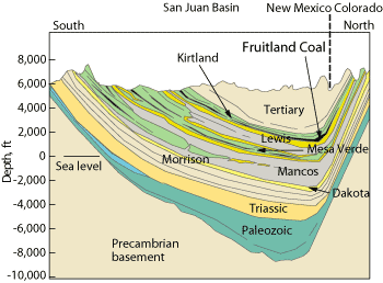
Coalbed methane development began in the 1980s. It creates issues with the continued development of deeper formations like the Mesa Verde and Dakota due to severe pressure depletion of the Fruitland Coal, Fig. 1.
 |
|
Fig. 1. This geologic cross-section runs south to north across the San Juan Basin.
|
|
The most obvious issue is lost returns. Lost time is typically two days and $50,000 in rig and spread costs, plus an additional $50,000 in mud, Lost Circulation Material (LCM) and water hauling costs.
Another issue is lost drilling fluids damaging nearby wells, which can result in lost production. To avoid this, current practice is to maintain a minimum 500 ft of separation between coal wells and deep development wells. This results in additional development and land use costs.
WELL DESIGN
The standard deep well design uses three casing strings. First a 12¼-in. surface hole is drilled and 95⁄8-in. surface casing is run and cemented to 200 ft. Next, an 8¾-in. hole is drilled and 7-in. intermediate casing is run and cemented to isolate the coal. Finally, a 6¼-in. hole is drilled with air and 4½-in. casing is run and cemented to TD. Typical production casing depths are 6,000 ft for Mesa Verde wells and 7,900 ft for Dakota wells.
CASING DRILLING
ConocoPhillips started drilling with casing in the south Texas Lobo Field in 2001.1 The operator has had good success using it to mitigate lost returns in sandstone, but did not know if casing drilling would eliminate lost returns in coal formations or if the technique would be economic in the San Juan Basin.
Casing drilling has proven to greatly reduce hole problems and improve well economics.1–3 Wells that were almost “undrillable” by conventional methods have been successfully drilled with casing.
Lost circulation problems are cured by the “smear effect,” where cuttings become LCM by being smeared across the lost circulation zone by the casing coupling as it rotates. To augment this, conventional LCM can also be added.
 |
|
Fig. 2. These show the differences between conventional drilling and casing drilling methods.
|
|
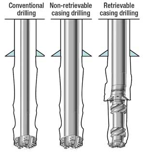
The basic types of casing drilling are shown in Fig. 2:
- Retrievable: The BottomHole Assembly (BHA) is locked temporarily into the bottom of the casing string and extends below the casing’s end with a reamer assembly and pilot bit. The assembly can be retrieved by a wireline winch.
- Non-retrievable: The bit used to drill the interval is cemented in the well and the bit is drilled up, similar to a float shoe.
An important part of casing drilling is rig capability. A casing drilling rig must be capable of running Range 3 casing joints (45 ft). It is also preferable that the rig be compatible with a casing drive tool. This tool is integrated relatively easily on a topdrive. Depending on the type and severity of well control issues, a split crown and traveling block may be used to install wireline BOPs on the topdrive. This facilitates pulling a BHA.
METHODS
The operator first had to explore the process and determine which method would be best. The retrievable system is more complex, requires more equipment and rig modifications. The non-retrievable system has fewer pieces of equipment and does not require as many rig modifications.
When the two options were placed side by side, the non-retrievable system seemed the best option. It was 22% less costly and simpler to implement. Also, it required no additional equipment on location and no rig modification for well control.
Based on this, a non-retrievable system was selected for the pilot program. The major issue was whether the casing drilling bit would drill the entire interval in one trip. The longest bit run to date was 2,600 ft. It would have to drill about 3,600 ft.
One of the most important components is the casing connection. The operator used 7-in., 23-lb/ft, P-110 casing with modified buttress connections successfully in South Texas. The standard casing design for vertical wells in the San Juan Basin is 7-in., 20-lb/ft, J-55 casing with a Short-Thread-and-Coupling (STC) connection.
The criteria for the pilot program were to minimize cost and provide casing that would meet the design loads. The standard STC connection would not support the 6,500 ft-lb torque required to drill the interval with Drill Pipe (DP). The casing connection eventually selected has a makeup torque in excess of 10,000 ft-lb.
The average number of cycles to drill the intermediate hole using conventional bits and DP is 216,000, based on drilling 3,600 ft at 120 ft/hr and 120 rpm. The assumption for the pilot was that the casing drilling process would drill at about half the ROP of a conventional PDC bit on DP. Engineers assumed it would take 374,400 cycles to drill to TD with casing, based on drilling 3,600 ft at 69 ft/hr and 120 rpm.
The team discovered that 7-in., 20-lb/ft, J-55 modified buttress connections either did not exist or had rarely been used. The operator decided to upsize to 7-in., 23-lb/ft, J-55 casing with a modified buttress connection.
Once the design was finalized, endorsement was gained to perform a five-well pilot program. The incremental cost to the wells was about $100,000. The majority of that cost could be offset if lost returns were eliminated.
PILOT PLAN
The plan was to drill five wells. Two runs with the casing drilling bit on DP were added to determine if the bit would be able to drill the entire 3,600-ft section. After two wells were finished, if there was confidence the bit could drill the entire interval, then casing drilling would begin using the non-retrievable design. If the bit was not able to drill the entire section, the retrievable system would be used on the initial five-well program.
All were Mesa Verde wells, which reduced program risk.
In the deeper Dakota wells, it is critical that the 7-in. intermediate casing be set below the coal. This isolates water and allows air drilling to TD. The Mancos shale, between the Mesa Verde and Dakota Formations, is very water sensitive. In the shallower Mesa Verde wells, 7-in. intermediate casing can be set above the coal, and then air/mist can be used to drill to TD.
DRILLING PERFORMANCE
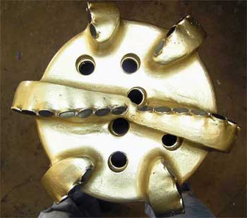
On the first run, a packed BHA was used with the casing drilling bit, Fig. 3. The bit drilled out the 9 5⁄8-in. casing; no float equipment was installed. The bit started drilling at 254 ft and was pulled at 3,109 ft. The drilling parameters were 50–115 rpm, 8,000–18,000 lb WOB, with 375–410 gal/min. The nozzles were six 18s. Details on all runs are in Table 1.
 |
|
Fig. 3. The initial bit design used.
|
|
| TABLE 1. Summary of casing drilling runs |
 |
|
The bit was graded 8-8-BT-A-X-3-LT-PR, and the proposed TD for this run was 3,923 ft. Based on this, additional gauge and shoulder protection were needed. The bit’s rupture disk had failed, so the rupture disk was removed from all future runs.
Run 2. The same bit was run on DP again. Gauge protection was added, and the rupture disk was welded shut. The BHA was slick. This pilot well was considered a severe test because below the normal geologic casing point the bit would be drilling much harder formations than normal. The planned intermediate casing point was at 4,551 ft.
The bit drilled from 230 to 1,014 ft, where the BHA was pulled because of inclination (6°). A roller-cone bit brought the well back to vertical, and the same bit was rerun with a packed assembly. It drilled from 1,790 to 3,126 ft and was pulled for penetration rate. The bit drilled to the standard casing point.
At this point, the team decided that casing drilling with a non-retrievable assembly could proceed with some design changes to the bit and BHA. The bit design change would further strengthen the gauge and the shoulder cutting area.
The initial plan assumed that the assembly would drill at 69 ft/hr. Based on the two DP pilot tests, the design needed to be robust enough to withstand a drilling rate of 44 ft/hr. This would result in 589,090 cycles, based on drilling 3,600 ft at 44 ft/hr and 120 rpm, which doubled the fatigue requirement. Based on operator experience, a 75⁄8-in., 47.1-lb/ft, P-110 BHA was added to improve fatigue resistance. The heavy-walled 75⁄8-in. casing is stiffer and more constrained in an 8¾-in. hole.
Run 3. This was the first time that the bit was run on casing. Bit design changes were not completed in time to drill this well, so the team decided to drill conventionally from the surface-casing shoe to just above the lost-returns zone. Then, casing drilling would be done through the coal interval, using the old bit design, to prove that casing drilling could eliminate lost returns.
The well was drilled with a conventional 8¾-in. PDC bit on a slick assembly from the surface-casing shoe to 2,932 ft. This was 50 ft above the coal formation and about 200 ft above the lost-returns zone. The assembly was tripped out, and the bit and packed BHA were run in. Two joints of the 7 5⁄8-in. heavy-wall, full-length casing were run.
The assembly had to be reamed to bottom almost from the time the bit entered the open hole to final depth because the BHA was so much stiffer than the slick assembly on DP. Once on bottom, the bit drilled 68 ft in 27.5 hr. It is likely that the shoulder area was damaged during reaming. The bit did not reach the lost-returns zone and was cemented in place just into the top of the coal formation.
An air hammer and hammer bit drilled out the float collar and the casing drilling bit, reaching casing depth in one run. Drilling through the casing drilling bit with an air hammer was a first, and an important part of proving that casing drilling could be successful.
Run 4. This was the first time that bit revisions were available. The bit’s shoulder area was strengthened significantly. A casing drilling bit, float collar, packed BHA and six joints of heavy-walled casing were run. Surface casing was drilled out with a conventional bit. Then, the assembly drilled from 345 to 3,865 ft in 119 hr.
Significant bit balling occurred, forcing WOB to be reduced. At 3,612 ft and 90 hr of drilling, standpipe pressure increased, likely due to plugged nozzles. Flowback was also seen on connections, indicating float collar failure.
Lost returns in the coal occurred at 3,615 ft, and the circulation rate was reduced from 450 to 200 gal/min. Drilling continued to 3,714 ft, where the rig was shut down. Total losses were over 3,000 bbl. No LCM was used. ROP in the interval was 9.7 ft/hr. Drilling was shut down for 5 hr to rebuild volume.
Once fluid volume had been rebuilt with 30% LCM, drilling resumed. After 10 ft, full returns were established. Drilling continued to section TD at 3,865 ft with full returns.
The slow penetration rate in the lost-returns zone likely did not produce enough cuttings for the smear effect to heal losses. The 5-hr shutdown, LCM and smear effect likely combined to heal the loss zone.
The casing was cemented in place. No cement was circulated to surface, but the top of cement was acceptable.
The float collar failed after 90 hr of drilling, allowing flowback, and was eliminated on the remainder of the program.
Run 5. This run proved that the bit could drill the entire section. The focus was to increase ROP to improve economics. Hydraulic Horsepower per Square Inch (HSI) and Equivalent Circulating Density (ECD) were targeted to improve drilling rate. The jets were reduced from six 16s to four 11s and two 14s. ECD was reduced by cutting the circulating rate and injecting air into the drilling fluid. The bit design was identical to that of Run 4 with the exception of the jets. Bit balling was less severe than before.
The surface casing string was drilled out conventionally, and open hole was drilled to 410 ft. The bit was tripped, and a casing drilling assembly was run.
The BHA was packed and contained six joints of the 75⁄8-in. heavy-walled casing. A cement stage tool was substituted for the float collar. The well was drilled at 450 gal/min. to 955 ft. There, air injection was started. Severe vibrations were noted when the DP was rotated at high speed. The air rate was staged up to 100 ft3/min., and then to 200 ft3/min., while the fluid rate was cut from 450 gal/min. to 350 gal/min.
Lost returns occurred briefly in the coal at 3,248 ft, but were immediately remedied. The assembly drilled with air to 3,501 ft in 43.5 hr. Casing was successfully used to drill through the entire lost returns zone without issues, and no LCM was used in the well.
Unfortunately at 3,501 ft, the casing parted in a connection 172 ft from the casing point. Materials left in the well included 13 joints of 7-in. casing plus the BHA, 881 ft in total. A spear successfully retrieved the parted casing in one attempt. Numerous joints were severely bent. A new string of 7-in. casing was run and cemented in one stage using foam cement.
Severe vibrations were seen, causing the maximum surface rotation speed to be limited to between 80 and 90 rpm. Vibration was likely caused by rotating non-straight casing joints.
Fatigue failure occurred in the thread run out in the field-makeup end of the 7-in. casing. The joint that failed was at the neutral point of the string and would have seen both tension and compression, depending on bit weight. The failure was likely a result of bent rotating casing, causing vibration, along with cycling from tension to compression without stabilization.
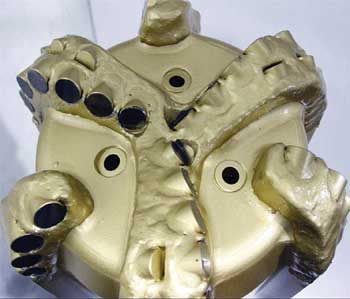
Run 6. The sixth well had a number of revisions to improve performance. The two focus areas were improving ROP and eliminating fatigue failure. The bit was redesigned to include six blades, with three to center and three on the gauge, Fig. 4. The junk-slot area was enlarged, and the design included only three jets. With the jet reduction, the total flow area was reduced, increasing HSI.
 |
|
Fig. 4. The final bit design has three blades to center with back-up cutters and only three nozzles to improve HSI.
|
|
To eliminate fatigue failure, the BHA was redesigned. The BHA was packed and included 14 joints of heavy-walled casing. This design allowed up to 23,000 lb of bit weight to come from the heavy-walled casing and would keep the neutral point in the 7 5⁄8-in. casing. All casing joints were rolled on the racks, and only straight joints were sent to the rig.
The assembly drilled without any losses from 702 to 3,425 ft. in 39.5 hr. Bit balling was eliminated, facilitating higher WOB. Vibration was significantly reduced, allowing higher rotation speed.
ROP in excess of 200 ft/hr was seen, similar to conventional PDC bits. Overall ROP was slower because aeration of the fluid made connection times longer. The liquid flowrate was 350 gal/min. with 200 ft3/min. of air pumped.
A one-stage foam slurry was pumped, and 50 bbl of cement were returned to surface. An air hammer was used to drill out the cement stage tool and casing drilling bit.
RESULTS
The pilot casing drilling project was a success, since lost returns were eliminated in the depleted coal formation. All three pilot wells that drilled through the depleted coal formation experienced lost returns, and all three were healed.
Changes to the bit design resulted in a number of significant learnings and firsts. The pilot program extended the length that the casing drilling bit drilled, from 2,600 ft to 3,520 ft, a record at the time.
The bit was enhanced and became similar to a traditional PDC bit, while maintaining the ability to be drilled out. Hydraulics were improved. Total flow area started at 1.49 in.2 and was reduced to 0.39 in.2 This increased the HSI from 0.22 to 2.2. The increase in HSI, combined with the improved junk slot area and three-nozzle design, virtually eliminated bit balling.
The pilot program proved that a non-retrievable casing drilling assembly can be used in the San Juan Basin and drill at high ROP with proper BHA design. Non-retrievable casing drilling assemblies require higher WOB to drill than retrievable systems do. Use of 14 joints of 7 5⁄8-in. heavy-walled casing provided the weight and stiffness required to produce drilling rates similar to those of conventional PDC bits.
A packed BHA is critical to avoid deviation problems.
A float collar was run in two of the four wells. On the second well, it failed. Since the ROP increased significantly, it may be worth looking at running the float collar again. A float would help in well control situations and prevent backflow from plugging the bit.
The cementing stage tool was successfully used in the final two wells. In the fifth well, it was pulled after the fatigue failure and function tested successfully. In the sixth well, it was used successfully after drilling for 39.5 hr, opening and closing as designed. There were some difficulties drilling the stage tool out with the air hammer. Unless two-stage cementing is required, the stage tool could be eliminated. The cementing stage tool proved tough enough for the drilling environment.
The casing design was a success, with the casing connections providing adequate torque capability. It is critical to have straight pipe.
Use of a rig designed for casing drilling was important. The rig equipment already included an integrated topdrive, a casing running tool and an integrated air package. Because these items were included in the rig rate, no rig modifications were required.
CONCLUSIONS
The most important conclusion from the pilot test was that lost returns were successfully mitigated by using casing drilling in a coal formation. Based on the pilot program, the major focus going forward will be to make casing drilling economic. Achieving ROP comparable to conventional drilling is a key factor.
A revised BHA has already been proposed and modeled that would eliminate high-cost, heavy-walled 7 5⁄8-in. casing. Analysis shows that stabilizing every joint of the portion of the 7 in., 23.0-lb/ft, J-55 casing that is run in compression could provide the required WOB and eliminate fatigue issues.
There is ongoing pilot testing that could reduce the cost of stabilizers. If the BHA cost can be reduced, casing drilling can be economic. The casing design was adequate. There may be some potential to downsize the 7-in. casing from 23 lb/ft to 20 lb/ft, but that is a non-standard connection for casing drilling, which may be difficult to obtain and more expensive.
There are other operational issues that must be considered to make casing drilling successful. These are straight casing, good hydraulics and reducing ECD to improve ROP.
Based on the pilot, a one-stage cement job is possible with foam cement. This saves about $20,000 per well.
It is important that the drilling rig is capable of doing the work. The economics will be significantly different if a casing running tool, air package, topdrive or an integrated BOP must be rented.
The ROP improvement from eliminating bit balling requires jets that are smaller than desirable for cementing. Either a separate tool with a rupture disk to cement though needs to be developed or a rupture disk should be integrated into the bit.
Drilling out the casing drilling bit with the hammer bit and air hammer was important. There are still concerns regarding the hammer bit’s ability to survive to TD in the air hole on a Dakota well, some 2,000 ft deeper.
Based on the last two wells drilled, where lost returns were minimal, future wells drilled with casing could reduce formation damage in offset wells.
ACKNOWLEDGEMENTS
The authors thank Michael Cortez and the engineering staff of Hughes Christensen for changing bit design quickly. Special thanks also to Robert Strickler and Dennis Moore, and the ConocoPhillips Upstream Drilling and Production Technology group, for assistance in analyzing designs and operating practices. The authors also thank the Helmerich and Payne Aztec field office team, Rig 282 supervisors and crews for making this successful. This article was prepared from IADC/SPE 112545 presented at the 2008 IADC/SPE Drilling Conference held in Orlando, Fla., March 4–6, 2008.
LITERATURE CITED
1 Fontenot, K. Highnote, J., Warren, T. and B. Houtchens, “Casing drilling activity expands in South Texas,” SPE/IADC 79862 presented at the SPE/IADC Drilling Conference in Amsterdam, Feb. 19–21, 2003.
2 Griffin, R. C., Kamruzzaman, S. and R. D. Strickler, “Casing drilling drill collars eliminates downhole failures,” OTC 16569 presented at the Offshore Technology Conference in Houston, May 3–6, 2004.
3 Houtchens, B., Foster, J. and R. Tessari, “Apply risk analysis to casing while drilling,” SPE/IADC 105678 presented at the SPE/IADC Drilling Conference in Amsterdam, Feb. 20–22, 2007.
|
THE AUTHORS
|
 |
Shon Robinson earned a BS degree in mechanical engineering from Brigham Young University and an MBA degree from Saint Mary’s University. He has worked in California, Colorado, New Mexico, Texas, Wyoming and offshore locations in the GOM and Eastern Canada. Robinson works as the Engineering Supervisor in ConocoPhillips’ Farmington, New Mexico, office.
|
|
 |
Tom Bealessio earned a BS in mechanical engineering from California Polytechnic University. He has been involved in drilling, completion and workover operations in numerous US locations, the Arabian Gulf, Nigeria, Trinidad and Tobago, Venezuela and Indonesia. Bealessio is a Senior Staff Drilling Engineer with ConocoPhillips.
|
|
 |
Randall Shafer earned a BS degree in engineering from Penn State and an MBA degree from the University of Chicago. His focus is on Arctic drilling and extending new technology throughout the company. He has worked in Russia, Norway, Africa and the UK. Shafer works in ConocoPhillips’ Corporate Drilling Technology Group in Houston, Texas.
|
|
| |
|


