Part 1—Introducing developments in ESPs, sucker rod pumping and gas lift.
James F. Lea, PL Tech LLC; and Herald W. Winkler, Texas Tech University
Recent developments in Electric Submersible Pump (ESP) systems include pumps that can handle high volumes of gas, are wireline-retrievable, or are designed for extreme pressure and temperature environments, such as steam-assisted gravity drainage projects.
Besides ESPs, we describe six new downhole and surface equipment developments in sucker rod pumping and gas lift. Sucker rod pumping is the most widely used form of artificial lift, in which a downhole reciprocating pump is operated using vertical rod motion or cables. Gas lift uses downhole valves to inject annulus gas into the tubing beneath liquid columns, or under plungers, to reduce column density and drive liquids to surface.
ELECTRIC SUBMERSIBLE PUMPS
Seven companies have developed nine new ESP tools and technologies.
High-lift stages for REDA systems. Schlumberger’s Artificial Lift segment has introduced the first set of five new high-efficiency, high-lift stages for the Reda ESP systems, with flowrates from 1,500 to 11,000 bopd.
As electrical power is one of the greatest costs of lifting fluid from a well, high-efficiency pumping can be critical to profitable production from marginal wells. The new stages for the Reda systems have a high lift per foot of length, resulting in fewer connections, fewer consumables and faster installation time. Reduced pump lengths can provide a better fit for highly deviated wells.
Each of the pump models is available with a new abrasion-resistant keyless bearing design, constructed with harder materials, that prolongs the life of the bearings.
Variable-speed drive. VSD systems are used to protect and control ESPs as well as surface pumping systems. Schlumberger continues to refine its SpeedStar variable speed drive system, introduced last year with a medium-voltage drive (World Oil, May 2008). The new SpeedStar 519 SWD is a low-voltage, sine-wave drive that complies with IEEE 519 for harmonic reflection to the power supply. The drive’s integral sine-wave filter assures clean power upstream through the electrical components and to the motor. Previous systems, with 6- and 12-pulse diodes, reflected back harmonic distortions of up to 25%, creating challenges for the power supply system. The new VSD system has an integrated, 18-pulse, phase-shifting auto-transformer that reduces the footprint of the unit by eliminating the additional transformer and also reduces the reflected harmonics to less than 5%. The cost savings are realized in efficiency gains from the integral auto-transformer as well as the cancellation of damaging harmonics.
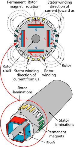
Permanent magnet motor. Borets-Weatherford has developed a Permanent Magnet Motor (PMM) system that can be used with both ESP and PCP systems. PMM design is fundamentally different from the ESP three-phase AC induction motor introduced nearly 90 years ago. The PMM is a three-phase, oil-filled motor with permanent magnets mounted in the rotor, Fig. 1. The PMM has a higher power density and thus is smaller than a similar-horsepower AC induction motor. The synchronous operation of the PMM further reduces losses in the core, thus reduces heating and expands the operating envelope of the motor.
 |
|
Fig. 1. Permanent magnet motor can deliver a 10%−30% improvement in overall system efficiency over AC induction motors, as demonstrated in field trials with one of the biggest Russian oil companies. The increased motor efficiency is partially due to not having to generate a stator magnetic field, which is instead generated by the permanent magnets.
|
|
Borets-Weatherford has installed more than 300 PMM-ESP systems to date, with run times exceeding 900 days, as well as a growing number of PMM-PCP systems.
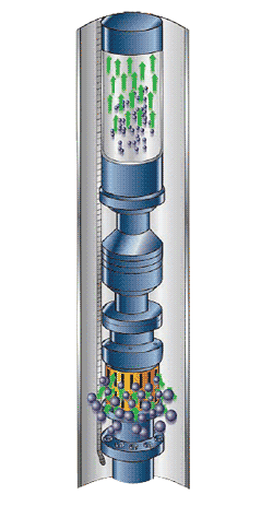
Centrifugal and axial pumps for high GOR. High gas-oil ratios are a challenge to produce with ESPs. An ESP can typically handle 10–20% free gas into the pump before gas locking occurs. Many attempts have been made to minimize the gas entering the pump; gas avoidance and separation methods such as shrouds, sumps and bottom feeder intakes, as well as reverse-flow and rotary-type separators, were all partially successful. Schlumberger has shown that by conditioning the two-phase fluid and priming the ESP, the gas can be used to provide a gas-lift effect in the tubing and actually reduce the hydraulic horsepower required to lift the fluid. This, in addition to increasing the free gas handling up to 75% in the pump, has opened new horizons for ESP pumping. The Advanced Gas Handler pump and the Poseidon Multiphase Axial Pump (Fig. 2) have enabled higher drawdowns and successfully produced wells previously thought to be off-limits for ESP systems.
 |
|
Fig. 2. The Poseidon multiphase axial gas-handling system is installed below the main production pump to process gas volume fractions as high as 75%.
|
|
High-temp ESP for SAGD. Several companies offer high-temperature ESP systems to use in SAGD operations.
Schlumberger has installed more than 450 Reda Hotline high-temperature ESP systems in steam-assisted gravity drainage wells, with wellbore temperatures reaching 218°C (425°F). With the development of the Advanced Motor Protector metal bellows expansion chamber system, high-temperature bearings and elastomers, and high-temperature cable systems (World Oil, May 2008), the Reda Hotline system has achieved a 4.5-yr run life.
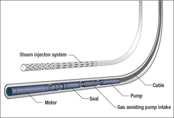
Baker Hughes Centrilift is developing the UltraTemp ESP system, including the new 450SP ESP motor, rated to 540 hp, Fig. 3. The system will be rated to 250°C (482°F) fluid temperatures. To achieve this milestone, the company has invested in a next-generation hot loop to test ESP systems up to 300°C (572°F) fluid temperatures in a near-horizontal orientation. Additional features of the new test loop include pressure rated to 3,000 psi; 12-in. inside diameter; 100-ft-long vessel, set at a 5° incline; target flowrate up to 1,575 m3/day (10,000 bpd); and total fluid capacity of about 1,700 gallons of water. Field trials of ultra-temperature ESP components are planned in the second quarter of 2009.
 |
|
Fig. 3. The Centrilift UltraTemp ESP system is rated to 482°F fluid temperature.
|
|
Wireline-retrievable ESP development. Existing retrievable ESP configurations have been deployed with conventional tubing, torque-balanced cable, coiled tubing, powered coiled tubing (cable run inside) and through-tubing, but they seldom receive preventative maintenance due to retrieval cost. Wireline-Retrievable ESPs (WRESPs) would be less expensive to service or replace when they fail or perform suboptimally. Wireline could also be used to run sacrificial ESPs to clean wells or test ESP designs.
Following successful downhole tests in Oklahoma in 2005, Shell International E&P and Wood Group ESP Inc. outlined the first WRESP system at an SPE ESP workshop in April 2007. Shell described the WRESP concept as “a step change in ESP system lifecycle management and operating philosophy.”
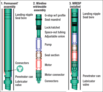
The WRESP system includes permanent components (re-entry guide, ESP cable, landing nipple) and retrievable components (motor, seal, pump, etc.). Shell engaged Diamould Ltd. to develop and test WRESP connectors to 5,000 psi and 121°C.
Shell and Petroleum Development Oman field-tested the WRESP system in the Rima-36 well, South Oman, in June 2007 and presented results in February 2008 at the European Artificial Lift Forum in Aberdeen. The Oman field test was partially successful (installation and mechanical functionality of components and wireline), but the electrical integrity of the ESP was lost prior to startup.
Commercial WRESP systems have also filtered into the market, beginning with the OptiLift system from Optilift Inc., now Zeitecs.
Because ESP technology requires heavy rig or hoist intervention to replace failed or suboptimal systems, the unpredictability of ESP failures results in significant disruption, cost and production deferment. The business case for the ESP Shuttle System (Fig. 4), where the entire ESP system (pump, seal and motor) can be run and retrieved on wireline, centers around improving disruptions, cost and oil deferment while reducing the health, safety and environment implications of frequent heavy workovers.
 |
|
Fig. 4. Zeitecs ESP Shuttle System.
|
|
The Zeitecs shuttle system for running and retrieving ESPs also provides the opportunity to run temporary, sacrificial systems to clean wells of the debris and transient solids often responsible for premature failure, and to test systems to measure well productivity and enable proper design. Furthermore, the ESP shuttle could effect a step change in ESP operating philosophy by facilitating preventative maintenance, inspection and servicing.
The ESP cable and the female electrical connectors are run with tubing as the “permanent” completion, and then the ESP shuttle system with the male electrical connectors is run through the tubing on wireline to the docking station at bottom. The wireline is detached and retrieved before production. The company is lining up field tests of the system in Oman and Brunei for second-quarter 2009 and developing options off the US.
SUCKER ROD PUMPING
Eleven new technology advances from seven companies introduce improved sucker rod pumping systems.
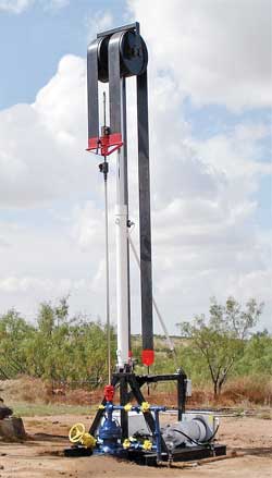
Hybrid pump. The new Dura-Lift hybrid pumping unit developed by Springtown, Texas-based Chaparral Automation is based on a hydraulic-electrical hybrid regeneration system. It provides a simple counterbalance and speed control during the downstroke with no heat buildup from the energy produced by the polished rod load. The pump is lifted with a hydraulic pump and cylinder.
The hybrid system converts the downstroke polished rod energy into usable electrical energy, which acts as a counterbalance and never requires operator adjustment, even as ambient temperature, well conditions or polished rod loads change. The pump is equipped with a microprocessor and a variable speed control.
The Dura-Lift pump system works similar to a hybrid car in which the electric motor becomes a generator whenever the driver hits the brakes. The atmospheric inlet pump is stroked over center, reversing the direction of flow without reversing the electric motors, making the pump a motor that meters out oil from the ram. The polished rod load on top of the ram forces the ram down. Pumping the oil back into the hydraulic motor drives the electric motor at faster-than-synchronous speed. At this point, it becomes a generator returning the energy from the polished rod back into a bidirectional kilowatt/hour meter or net metering power grid for overall power savings.
The system does not use nitrogen gas for counterbalance, meaning no high-maintenance nitrogen gas accumulators, large storage bottles or multiple chamber cylinders are required. The single-acting ram has no piston seals, and the rod packing can be replaced in the field, Fig. 5.
 |
|
Fig. 5. Chaparral Automation LLC developed the Dura-Lift hybrid pumping unit with a hydraulic-electrical hybrid regeneration system that does not require nitrogen gas for counterbalance.
|
|
The Model 1111 controller automatically adjusts the motor displacement on the downstroke, controlling the speed, which controls the counterbalance. On the upstroke, it controls the speed by adjusting the pump displacement. Chaparral Automation is conducting field testing with an operator to get a better idea of potential energy savings with the hybrid pumping unit.
Solid control plunger, valves. Four related rod-pump technologies have been developed by St. George, Utah-based Eagle Innovations Inc. to combat problems related to valve rod loading in high concentrations of frac sands or in high-solids fluid. Eagle’s Cyclone Valve Rod Guide, Radial Cyclone Cage, Sure-Flow Plunger Valve and Cyclone E-Vac plunger adapter are further refinements of the Cyclone Plunger and Cyclone Pump System (World Oil, April 2008).
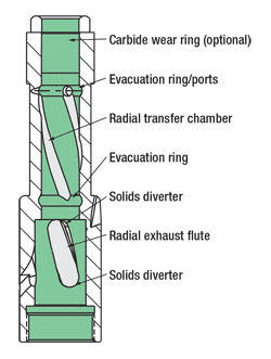
Sand, grit, iron sulfide and other fines often collect between barrel and plunger and contaminate produced oil and water. Eagle’s Sandmaster Series Cyclone Valve Rod Guide is designed to wipe away excess solids from the valve rod by not allowing them to move between the rod and the guide, Fig. 6. This is accomplished by three internal 360° radial, spiral grooves that wipe the rod clean of solids with the upstroke. If smaller particles do pass into the guide area, they are quickly wiped free from the rod and forced into the radial groove channels. That action routes any solids out through the top of the guide neck.
 |
|
Fig. 6. Eagle Innovations’ Cyclone Valve Rod Guide prevents accumulation of solids between the rod and the guide.
|
|
The radial flutes allow the fluid to pass through the guide as an energy-induced cyclone, effectively keeping entrained solids in an orbital state. The cyclone’s radial spin forces solids higher up the tubing and prevents them from falling back and collecting on top of the pump near the guide. The cyclonic motion also prevents solids from being pulled back into the barrel.
Eagle designed the rod guide with an offset at the top of the radial flute that will prevent solids from flowing back into the flute area when the well is shut down. The offset directs the solids away from the flute, and with its outward taper design, drives the solids further away from the inlet.
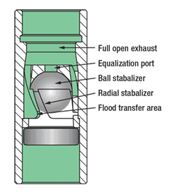
Eagle has developed new valve designs: Radial Cyclone Cage with Traveling or Standing Valves, and Sure-Flow Plunger Valve. Eagle’s patented traveling/standing valve’s Radial Cyclone Cage is another advancement in rod pump valve design, Fig. 7. This tool is formulated with a one-piece cage. Eagle’s radial design allows 30% more fluid to pass through the valve, via laminar flow. That eliminates violent ball action within the cage, eliminating the need for a hard liner. The ball containment design in the radial cyclone system enables the ball to gently place itself into a cradle, allowing the fluid to pass around the ball next to the cage wall. Eagle’s radial cyclone technology creates a low-pressure zone in the center of the cage and allows the high-pressure fluid to move around the ball. The ball moves more quickly and falls directly back onto the seat. This prevents slow valve closure and increases the pump effectiveness. This speed is especially valuable for high-flow standing valve cages in heavy crude environments. The new technology is also tailored for fluids with high solids content as it eliminates the ball and containment from sticking in the cage.
 |
|
Fig. 7. Eagle Innovations’ one-piece, high-flow, radial cyclone cage is available configured with either a standing valve or a traveling valve.
|
|
Eagle’s Radial Cyclone Standing Valve has benefits similar to the Radial Traveling Valve, as well as two additional features: The standing valve cage is designed with a near-zero space between the ball and the traveling-valve compressive area. This assists in gassy conditions where gas locking could become problematic. In addition, the cyclone system plays a key role in the proper filling of the pump barrel since the radial design allows for a faster fluid passage with greater flow capacity. The cyclone design forces solids within the fluid away from the seat area. As a result, the ball seats with less interference from debris and results in a longer run life for the ball and seat. Eagle says its new High-Flow Radial Cyclone Cage technology results in a stronger, longer-lasting pump.
The Eagle Sure-Flow Valve was designed to assist the traveling valve in gassy and dirty conditions.
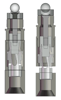
When a ball is stuck or prohibited from unseating, this patented feature will allow the ball to be unseated by a stem cradle. The stem hydraulically forces the ball off the seat. The cradle maintains control without impinging the ball with the cradle stem. The cycle is completed by the cradle maintaining fluid in the cavity below the ball and seat. The cycle repeats when the stem is actuated by a full open-bore drag plunger attached to the bottom assembly of the stem mechanism. The stem mechanism is designed with patented radial ports to allow heavy or high-solids-content fluids to pass through the valve, eliminating concerns about sticking or premature wear. The radial design keeps the stem mechanism free of debris with no interruption in stem action, Fig. 8.
 |
|
Fig. 8. The radial stem design of Eagle Innovations’ Sure-Flow Valve facilitates greater fluid flow through the valve by a positive open on each stroke.
|
|
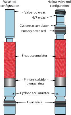
Eagle Innovations designed the Cyclone E-Vac Plunger system to prevent stuck pump plungers and premature wear on barrel and plunger surfaces by preventing sand, grit and other fines from accumulating between the barrel and the plunger, Fig. 9. During the normal up-and-down motions of the plunger, accumulated particles cause rapid wear, usually in the form of vertical scoring, to the plunger and barrel surfaces. Friction generated by accumulated sand and grit causes excessive stress throughout the pump and rod string, often resulting in a stuck pump, automatic shutdown of the pumping unit or a parted rod string.
 |
|
Fig. 9. The Cyclone E-Vac Plunger system from Eagle Innovations can be added to sucker rod pump assemblies to reduce damage from sand and grit.
|
|
During the downstroke, the Cyclone E-Vac Plunger, along with the Cyclone Seat Plug, forces any particulates entrained between barrel and plunger inward through the axial evacuation ports and into the center of the plunger. Here, they commingle with fluids entering the pump and are displaced into the tubing. Throughout the upstroke, particulates are also collected within the tapered neck of the plunger, where, during the downstroke, they are flushed upward and enter the tubing through the Cyclone Top Plunger Adapter, which features radial ported vanes.
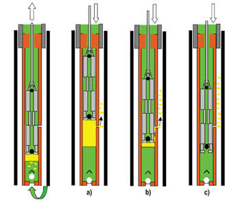
Gas vent pump. Harbison-Fischer, based in Fort Worth, Texas, has recently patented its Gas Vent Pump, a new concept in sucker rod pumping. It separates gas from fluid, producing gas up the casing-tubing annulus and virtually gas-free fluid up the tubing, Fig. 10.
 |
|
Fig. 10. Harbison-Fischer‘s Gas Vent Pump separates gas from fluid.
|
|
The pump is available as either an RH top hold-down or TH tubing pump configuration with a perforated coupling between the upper and lower barrels or a group of strategically placed vent holes located in an RW or RH top hold-down barrel. Operating the pump on the upstroke and downstroke is similar to operating a standard sucker rod pump. The standing valve admits the fluid-gas mixture to the compression chamber on the upstroke, and the two traveling valves open on the downstroke to pass fluid to the tubing above the pump to be lifted to the surface on the next upstroke.
The design feature that makes this pump a gas separator is that the lower plunger passes above the vent ports on the upstroke, allowing gas to escape from the compression chamber into the casing-tubing annulus before the downstroke begins, Fig. 10a. Gas that remains in the compression chamber is forced between the plunger and the barrel on the downstroke and out the gas vents, Fig. 10b. This allows the traveling valves to open when the lower traveling valve hits the fluid, and the fluid forms a fluid seal between the plunger and the lower barrel, Fig. 10c. Note that the upper, soft-packed plunger always strokes above the vent ports and holds back the hydrostatic pressure above the pump.
This unique pump has been successfully installed in more than 500 wells, eliminating gas locking and gas interference, and in some cases increasing gas production since it can pump the well down further than other sucker rod pumps. 
Acknowledgements
The authors thank the featured companies for providing the information for this article. The authors are not responsible for claims made by the manufacturers and vendors about their products’ capabilities.
|
THE AUTHORS
|
| |
James F. Lea teaches courses in artificial lift and production for Petroskills. He holds BS and MS degrees in mechanical engineering from the University of Arkansas and a PhD from Southern Methodist University. He worked for Sun Oil as a research engineer from 1970 to 1975, taught at the University of Arkansas from 1975 to 1978, was team leader of production optimization and artificial lift at Amoco EPTG from 1979 to 1999 and was chairman of Texas Tech University’s petroleum engineering department from 1999 to 2006.
|
|
| |
Herald W. Winkler is former chairman of and now a professor emeritus and research associate in Texas Tech University’s petroleum engineering department in Lubbock, Texas. He works as a consultant in artificial lift, specializing in gas lift.
|
|
| |
|


