A 57,000-bps transmission rate enhances real-time monitoring.
Tarab Ali and Ananth Srinivasan, Baker Hughes Inteq; Stephen Edwards and Jim McKay, BP America Inc; Maximo Hernandez, IntelliServ Inc.; and Michael Reeves, NOV
This article discusses the successes and lessons learned during the first deployment of IntelliServ’s High-Speed Telemetry Drill Pipe Network with Inteq’s Rotary Closed Loop System (RCLS) AutoTrak and Triple Combo suite in North America. The article details the operational experience while drilling two lateral wells with an emphasis on drilling optimization and LWD processing with the ability to receive real-time, memory-quality data via a telemetry drill pipe network.
In addition to the improvements in LWD technologies, there has been a remarkable development of downhole drilling dynamics and optimization tools. A telemetry drill pipe network that delivers real-time, memory-quality data at 57,000-bps transmission rates provides a step change in capability for the industry-dramatically changing the decisions that can be made in real time.
The major lessons learned while drilling the lateral wells were: 1) real-time monitoring is a valuable tool for controlling and mitigating dynamic dysfunctions downhole, resulting in immediate ROP improvements; 2) high-resolution borehole images via telemetry drill pipe facilitate real-time on-site dip picking and analysis of downhole conditions; 3) high-resolution real-time images facilitate decisions regarding casing setting depth and/or elimination of an entire casing string (as seen in the second lateral well); 4) high volume of real-time memory data imposes new challenges on surface software systems; and 5) handling of telemetry drill pipe at surface plays a key role in improving the efficiency of overall drilling operations.
With a high-speed telemetry drill pipe network, drilling engineers can have high-quality downhole dynamics information and Mechanical Specific Energy (MSE) data in real time while drilling. Likewise, the geologists and petrophysicists can have access to 8-sector gamma images and 16-sector density images, both in real time via high-speed telemetry drill pipe. The operational success of telemetry drill pipe at Wamsutter also makes a strong case for deploying this technology in the deepwater GOM.
INTRODUCTION
The telemetry drill pipe network was commercially introduced in early 2006. The design concept of telemetry drill pipe is based on electromagnetic induction, where an alternating current or voltage in one coil induces varying magnetic field in the ferrite core, which in turn induces alternating current in the second coil placed in proximity. The ferrite core and inductive coil are located on the box and pin end of second-generation double-shouldered connections.
The data cable, which is encapsulated within a pressure-sealed conduit, travels inside the body of the tool joints and enters into the internal diameter of the telemetry drill pipe at the internal upset. A detailed description of telemetry drill pipe design can be found in the literature.1-5
Telemetry drill pipe networks have successfully transmitted data at a rate of 57,000 b/s in several field trials.6 The data rates demonstrated by this technology are significantly higher than the standard mud-pulse telemetry (8 to 12 b/s). Electromagnetic telemetry can deliver rates up to 100 b/s, but still is nowhere close to the bandwidth available with high-speed telemetry drill pipe network.
The first deployment in North America of IntelliServ’s high-speed telemetry drill pipe network was in conjunction with Inteq’s RCLS and a triple combo logging suite. Previous deployments of this technology with RCLS/LWD/triple combo include Troll Field, in the North Sea, where two extended lateral wells were drilled, and offshore Myanmar, where a commercial well was drilled for pressure management.7
The two subject lateral wells were drilled in the Wamsutter Field, Sweetwater County, Wyoming. High-speed telemetry drill pipe was deployed with an RCLS and MWD/LWD tools that measured gamma ray, resistivity, high resolution resistivity, pressure, density, neutron, acoustic and downhole drilling dynamics. The memory-quality data that was being transmitted to surface while drilling with this technology was previously only available once the MWD/LWD tools were on surface for downloading the memory data.
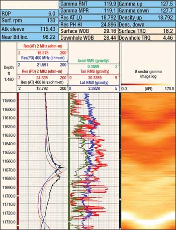
Some of the real-time data transmission capability that differentiated this technology from all the other telemetry systems included 16-sector density images, 8-sector gamma images, high-resolution resistivity images, a full suite of downhole drilling dynamics data (including bending moments, downhole WOB and torque on bit), and calculated downhole MSE data. Figures 1 and 2 show real-time images from Wells 1 and 2, respectively.
 |
|
Fig. 1. Real-time log with 8-sector gamma image, LWD and downhole drilling dynamics data as shown on proprietary web-based display software for Well 1.
|
|
 |
|
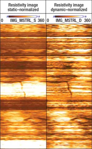
Fig. 2. Real-time, high-resolution resistivity images from Inteq’s StarTrak tool from Well 2.
|
|
PROJECT BACKGROUND AND OPERATOR’S EXPECTATIONS
Wamsutter Field, encompassing about 1,700 sq mi, is located in southwest Wyoming and is one of the largest tight-gas resources in North America.8 The field was discovered in late 1950s, and the primary productive interval in the field is the Almond Formation, the youngest formation in the Mesaverde Group.9
Trial objectives.
The main objectives of the field trials were:
- To minimize HSE incidents
- To learn how to handle telemetry drill pipe
- To assess reliability of the telemetry drill pipe network
- To establish accurate directional control and geo-steering
- To optimize ROP performance and BHA dynamics control (the operator experience demonstrated that vibration and stick-slip events were an issue due to the hard formations)
- To test the feasibility of deploying high-speed telemetry drill pipe network with RCLS and a full suite of MWD/LWD tools.
ASSESSING POTENTIAL FOR THE NEW TECHNOLOGY
High-speed telemerty drill pipe’s advantages arise out of the following cost-saving benefits.
Improving drilling efficiency and time savings. Trips from MWD failures can be avoided with telemetry drill pipe/mud pulse telemetry redundancy. Additional time can be saved by sending up survey data and downlinking to RCLS and MWD/LWD tools. Furthermore, tool reliability can be improved by continuous downhole monitoring of shock, vibration and bending moments. Additional trips can be avoided by diagnosing and fixing them via the network.
High-speed telemetry drill pipe networks also provide real-time, high-resolution downhole drilling dynamics for maximizing drilling efficiency (downhole MSE) and minimizing vibration modes (stick-slip, bending moments, downhole torque, etc.). Real-time, high-resolution density and resistivity images are available for casing-setting depth and/or total elimination of an entire casing string.
Improving wellbore delivery. High-speed telemetry drill pipe networks also provide real-time memory-quality wellbore images for geo-steering and wellbore placement. Real-time wellbore stability and wellbore pressure management can also be improved with real-time memory-quality wellbore images, caliper data and annular pressure measurement while drilling and reaming. Also, hole quality can be enhanced through continuous two-way communication with RCLS and MWD/LWD tools.
DRILLING OPERATIONS
Both subject wells were horizontal wells drilled to evaluate and set production liners in the Almond Formation. The following is a brief summary of the drilling operation for both wells.
Well 1. The directional program in the 8½-in. hole specified that the hole angle to be built at 4.0°/100 ft, from 82° to 96°, and then drop back to 92°. The 8½-in. BHA included RCLS with MWD/LWD tools increasing gamma ray, resistivity, pressure (OnTrak), density and neutron (LithoTrak), acoustic (SoundTrak) and downhole drilling dynamics (CoPilot).
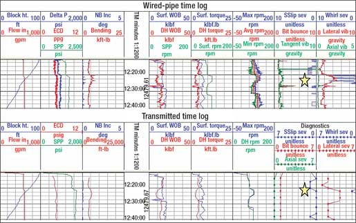
The well was successfully drilled to TD with a few challenges that were overcome by proper bit selection and by real-time monitoring of downhole drilling dynamics and wellbore images. One of the key measures of success realized during this operation was seamless switching from wired-pipe telemetry to mud pulse telemetry when the upper communication bus was lost in the MWD/LWD tool. In many instances, drilling dynamics malfunctions were mitigated by real-time monitoring of memory-quality downhole drilling dynamics data, Fig. 3. As shown by the star in Fig. 3, the wired-pipe, real-time log catches the whirl event in detail while the mud-pulse log shows only a point. The high-density data of the whirl event helped the directional driller to reduce RPMs and avoid downhole whirl.
 |
|
Fig. 3. Comparing the drilling dynamics data logs from wired-pipe telemetry and mud pulse telemetry.
|
|
Well 2. For this well, the directional program specified for the hole angle to be built from vertical to 92°. The well was drilled in 12¼-in. and 8½-in. hole sections with high-speed telemetry drill pipe network deployed in the 8½-in. section. The 8½-in. BHAs included the RCLS, in conjunction with MWD/LWD tools including gamma ray, resistivity, pressure, density and neutron, high-resolution resistivity imaging tool and downhole drilling dynamics.
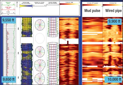
More challenges were encountered in Well 2 regarding drilling dynamics mitigation (especially stick-slip) as compared with Well 1. These challenges were again overcome by changing bit-selection criteria and BHA design. One of the major objectives to eliminate the intermediate casing string was achieved when the 8½-in. hole was drilled all the way to TD, eliminating a 7-in. liner. Figure 4 shows images from the horizontal section of Well 2. The images were taken while reaming down. The wired-pipe images helped BP to leave the hole open; subsequently, the hole stabilized itself. The images also helped BP to drill the horizontal section all the way to TD, skipping the 7-in. liner. These images were taken at a trip rate of about 320 ft/hr. Also, a comparison is shown with the mud-pulse image.
 |
|
Fig. 4. Real-time density images that helped BP to eliminate an intermediate 7-in. liner, with direct saving of time and money and reduction in well complexity.
|
|
RESULTS AND LESSONS LEARNED
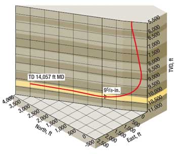
The operator’s major objectives were met with the delivery of a smooth wellbore to TD while staying within the Upper Almond Sand, without any HSE incidents. Figure 5 shows a 3D rendition of the lateral (from Well 1) in the Upper Almond Sand. The high-speed telemetry drill pipe network successfully provided: Real-time, memory-quality drilling dynamics and formation evaluation data, downhole MSE and high-resolution resistivity and density images.
 |
|
Fig. 5. A 3D rendition of the well path drilled for Well 1.
|
|
The major lessons learned during the deployment of high-speed telemetry drill pipe at Wamsutter Field revolved around issues described below.
Proactive drilling performance and vibration management. Downhole data was obtained from the service company’s drilling dynamics tool, measuring parameters such as downhole WOB, downhole torque and bending moments that can vary significantly during drilling operations. MSE was also calculated from the downhole measurements provided by the tool. These parameters were monitored in real time to manage vibration and optimize drilling performance throughout the section. The high-density drilling dynamics data from telemetry drill pipe was displayed every 10 s in Well 1 and 5 s in Well 2, allowing rapid response that lead to drilling optimization. Mud-pulse telemetry often transmits real-time drilling dynamics data with updates ranging from 60 to 180 s, which dilutes drilling dynamics information, preventing a proper diagnosis of downhole conditions.
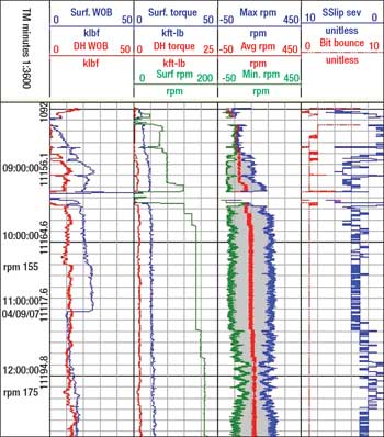
Figure 6 illustrates the real-time memory-quality downhole dynamics data transmitted via high-speed telemetry drill pipe that facilitated the instant response required to mitigate downhole stick-slip by increasing RPM.
 |
|
Fig. 6. Real-time memory log via telemetry drill pipe; RPMs were slowly increased to control stick-slip.
|
|
Improving drilling efficiency and time savings. Benefits included time saved by sending up survey data and downlinking to RCLS tools, by transmitting the information directly via telemetry drill pipe network. Time was also saved by avoiding trips by having telemetry drill pipe/mud pulse telemetry redundancy.
The improved two-way communication allows performing a comprehensive set of tool diagnostics that were previously only available once the tools are on surface, after a BHA trip. Improved tool reliability was also possible by the continuous monitoring of downhole stick-slip, vibration and bending moments.
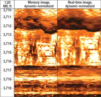
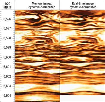
Improved wellbore delivery. Memory-quality wellbore images were transmitted, allowing for geo-steering and optimized wellbore placement. These memory-quality wellbore images, together with caliper data and annular-pressure measurement while drilling and reaming, enabled real-time wellbore stability and wellbore pressure management. With real-time memory images, the client is able to perform bed dip analysis, update its structural and seismic mapping and identify larger structural events such as faults and bedding, and understand lost circulation mechanism and borehole washouts while drilling. Figures 7 and 8 illustrate real-time, memory-quality, high-resolution resistivity images.
 |
|
Fig. 7. Faulting and stress-induced fracturing as shown in the resistivity image for Well 2.
|
|
 |
|
Fig. 8. Sediment deformation and cross bedding as shown in the resistivity image for Well 2.
|
|
Surface software challenges. Several improvements on the surface data-acquisition and processing system have been made since the first prototype deployment of multi-combo LWD systems with telemetry drill pipe network with a goal toward robust high-speed, real-time data handling at surface.
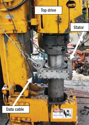
Data swivel and cable issues. A data swivel top drive was used in place of a saver sub and was identified as having high potential for being damaged if the driller did not have adequate control over stabbing when making up pipe, Fig. 9.
 |
|
Fig. 9. Top drive swivel sub showing the stator and data cable that connects the stator to the surface data acquisition server.
|
|
The alignment of the top drive was identified as being critical to prevent damage to the data swivel. Good visibility with the rig camera was critical for controlled top-drive makeup to the drill pipe (angle and focus). Increasing the sensitivity of driller’s joy stick, and making sure the top-drive grabber box was as deep as possible on the drill pipe box, was helpful in preventing mis-stabs. Securing the data cable correctly was identified as a way to prevent cable damage. In the future, development of a wireless data swivel will eliminate this problem.
Handling of telemetry drill pipe and BHA considerations. It is important to demonstrate to the drilling crew any non-standard BHA components, such as a circulating sub, well in advance of beginning operations with telemetry drill pipe. This will allow for proper wiring and testing of drillstring components.
CONCLUSIONS
The first deployment of high-speed telemetry drill pipe with RCLS/MWD/LWD in North America successfully demonstrated the ability to transmit high-bandwidth data in real time. The telemetry drill pipe network uptime (reliability) was 85% for Well 1 and 93% for Well 2. The successes during its deployment have further proven the compatibility of telemetry drill pipe network with the latest drilling and MWD/LWD technologies. This technology has improved the way drilling engineers, geologists and petrophysicists interpret and manage real-time data while drilling.
Real-time, memory-quality drilling dynamics data helps mitigate downhole problems instantaneously, which, in turn, leads to higher drilling efficiency and wellbore stability. Real-time, high-resolution gamma/density images and formation evaluation data facilitate reservoir assessment in. The real challenge in using the full potential of this technology lies in managing the high volume of downhole information available in real time. The success of wired-pipe telemetry, along with 400,000 ft and 40 wells drilled globally, means the new technology is ready for deepwater GOM. 
ACKNOWLEDGEMENT
This article was prepared from SPE 112636 presented at the 2008 IADC/SPE Drilling Conference in Orlando, Florida, March 4-6, 2008.
LITERATURE CITED
1 Jellison, M. J. et al, “Telemetry drill pipe: Enabling technology for the downhole Internet,” SPE 79885 presented at the IADC/SPE Drilling Conference, Amsterdam, Feb. 19-21, 2003.
2 Jellison, M. J. et al, “Intelligent Drill Pipe Creates the Drilling Network,” SPE 80454 presented at the SPE Asia Pacific Oil and Gas Conference, Jakarta, Sept. 9-11 2003.
3 Jellision, M. J. et al, “New developments in drillstem rotary shoulder connections,” SPE 62785 presented at the IADC/SPE Asia Pacific Drilling Technology, Kuala Lumpur, Sept. 11-13, 2000.
4 Reeves, M. et al, “High speed drillstring telemetry network enables new real time drilling and measurement technologies,” IADC/SPE 99134 presented at the IADC/SPE Drilling Conference, Miami, Feb. 21-23 2006.
5 Reeves, M. et al, “Intelligent drillstring field trials demonstrate technology functionality,” SPE 92477 presented at the SPE/IADC Drilling Conference, Amsterdam, Feb. 23-25 2005.
6 Manning, M. J. et al, “Processing wired pipe LWD-FE data in real time: Experiences and lessons learned,” SPWLA presented at the SPWLA 48th Annual Logging Symposium, Austin, June 3-6, 2007.
7 Hernandez, M. et al., “The first offshore use of an ultrahigh-speed drillstring telemetry network involving full LWD logging suite and rotary-steerable drilling system,” SPE 110939 presented at the SPE Annual Technical Conference and Exhibition, Anaheim, Nov. 11-14, 2007.
8 Schrooten, R. A. et al, “A case study: Using wireline pressure measurements to improve reservoir characterization in tight formation gas: Wamsutter Field, Wyoming,” IPTC 11545 presented at the International Petroleum Technology Conference, Dubai, Dec. 4-6 2007.
9 Newman, H. E., “Greater Green River Basin stratigraphy as it relates to natural gas potential,” SPE 9845 presented at the SPE/DOE Low Permeability Symposium, Denver, May 27-29 1981.
|
THE AUTHORS
|
|
|
Tarab H. Ali is a Drilling Engineer with Baker Hughes Inteq in Houston, TX. In his current role, he manages and coordinates deepwater drilling projects for a major GOM operator. Previously, Tarab worked as an offshore MWD/LWD Field Engineer with Sperry Drilling Services. Tarab holds a Masters Degree in Industrial Engineering from the University of Oklahoma. He can be reached at tarab.ali@inteq.com..
|
|
|
|
Ananth Srinivasan is a Drilling Engineering Manager with Baker Hughes. In his current role, he supervises GOM drilling projects. He previously held various positions in the drilling engineering team, field operations and sales. He earned an MS in engineering from the Colorado School of Mines.
|
|
|
|
Stephen T. Edwards works as a Geomechanics Specialist in the EPT Drilling Technology Group in Houston. Steve works within drilling technology’s ERA Flagship as project leader of the Wired Drillpipe Applications Project. Edwards graduated from the University of Oxford in 1991 with a bachelor’s degree in Geology and Geophysics and from the University of London in 1997 with a Ph.D. in Geomechanics.
|
|
| |
Maximo Hernandez earned a BS degree in electronic systems engineering and an MS degree in petroleum engineering and project management. With 16 years in the drilling industry, he has held positions in operations and management of wireline, directional drilling and drill bit operations in seven countries, including worldwide responsibilities for the design, development and commercialization of real-time drilling engineering and drilling optimization products for a major service company. Hernandez is presently the business development manager for IntelliServ.
|
|
| |
Michael Reeves is President for the NOV ReedHycalog and Downhole tools product lines based in Houston. He previously served as Vice President of IntelliServ Inc. and several operations management positions with Schlumberger’s drilling and measurements group. Reeves earned a degree in civil engineering from Imperial College in London.
|
|
| |
Jim McKay is a Drilling Engineer in BP’s Wamsutter technology team and has 7 years of industry experience. He joined BP in 2005 to work on non-conventional tight gas technology on the Wamsutter Major Project. He holds a BS in Mechanical Engineering from the University of Texas at Austin and is currently earning an MBA from Duke University’s Fuqua School of Business.
|
|
|


