Meeting the new needs of the deepwater Phase IV development required balancing the system’s multi-phase electrical differences.
Mamdouh Farouk and Mohamed Gaber, Burullus Gas Co.
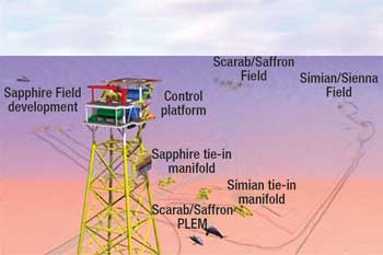
The West Delta Deep Marine (WDDM) concession in the deep water offshore Egypt’s Nile Delta contains three main development areas: Scarab/Saffron, Simian/Sienna and Sapphire Fields, each with up to eight Phase I wells in 400-1,200 m water depth. Wells at each field are connected to a Subsea Distribution Assembly (SDA) for control, and to subsea manifolds for gas collection. Each field’s export lines move gas production to the subsea PipeLine End Manifold (PLEM). From the PLEM, two main export lines carry gas to the onshore terminal.
Phase IV development is an expansion to both Scarab/Saffron and Simian Fields. There are seven wells to be tied in with the existing Scarab/Saffron Fields that produce via two manifolds and infield pipelines into existing 24-in. and 36-in. offshore pipelines. One well is to be tied into Simian Field.
This article describes the challenge Burullus Gas faced to accommodate an additional seven wells into the existing system with the new control system modules’ power consumption.
FIELD LAYOUTS
Scarab/Saffron, Simian and Sapphire Fields each comprise eight wells from Phase I, Fig. 1. Wells at each field are connected to an SDA for control and to subsea manifolds for gas collection. Each field’s export lines carry gas production to the PLEM, located in 95 m water depth, and then on to two export lines.
 |
|
Fig. 1. Scarab/Saffron, Simian and Sapphire Fields each have eight wells that produce gas to the PLEM, and then on to two main export lines.
|
|
Scarab/Saffron’s control umbilical runs about 90 km from an SDA to the onshore terminal. This is the second-longest direct-distance subsea tieback. Simian and Sapphire control umbilicals run from an SDA to the platform and after that to the onshore terminal.
Simian Field has eight wells separately connected to an SDA to distribute signals, power, methanol and glycol by infield umbilicals through the Umbilical Termination Assembly (UTA) and flying leads. The SDA is connected to the control platform through the main umbilical carrying hydraulic, electrical/communication control signals and methanol injection. A 4-in. glycol line runs from the onshore terminal directly to the SDA, Fig. 2.
 |
|
Fig. 2. The Simian SDA is connected to the control platform through the main umbilical.
|
|
Sapphire Field has eight smart wells that each produce from two zones and are separately connected to the field’s SDA, which is located very close to the manifold area to distribute the signals, power, methanol and glycol by infield umbilical through the UTA and flying leads. The SDA is connected to the control platform through the main umbilical that carries the hydraulic, electrical/communication control signals and chemical injection. A 4-in. glycol line will run from the onshore terminal directly to the SDA, Fig. 3.
 |
|
Fig. 3. The Sapphire SDA is connected to the control platform through the main umbilical.
|
|
SUBSEA CONTROLS
A subsea field’s power and communication requirements are key issues for any field expansion study. Common questions are: What are the communication and the power requirements for the subsea equipment? What is the difference between conventional and subsea equipment?
Power. Different modes should be considered during control module power consumption analysis, including idle, scan and valve-command modes. Power consumption for each Subsea Electronic Module (SEM) is around: 40-60 W during idle, 80-100 W in scan and 140-165 W in valve-command mode. These are based on 30 VAC at the rectifier bridge.
Communication. Communication within the subsea field is normally through paired cables. On some occasions, fiber optic cable may used to increase transferred information. In Burullus’ subsea projects, fiber optic cable was used as a permanent system because of platform information that needed to be transferred onshore, not for subsea control needs.
Hydraulic. Pressure needs ranged from 5,000-7,200 psi. The control fluid used was Castrol Transaqua HT with a viscosity of 5 cSt at 15°C with no entrained air and a relative density of 1.0706 at 20°C.
CONCEPT SELECTION
After completion of Scarab/Saffron, a conceptual design phase covering Simian Field was begun. Conceptual challenges included the evaluation of different control options, evaluation of new technologies, schedule impact, use of proven technology, step-out from shore (105 km), water depth and the preference for a subsea-control option.
These challenges led to several options: one for primary control and six for secondary control. The first option would extend primary control from the Scarab/Saffron development. Options for secondary control were more varied and included new development: from onshore, from onshore plus a link, from Rosetta Field plus a link, from the floating control mooring and from Rosetta Field.
Technical considerations included: hydraulic supplies, electrical power supplies, communications, electrical, satellite (VSAT) link, umbilical configuration and additional qualification requirements.
A new platform linked with Rosetta Field had the lowest cost, but the deciding issue was the reliance on third parties. The final technical recommendation for Simian’s control system was to use direct control from the onshore facilities with no link to the Scarab/Saffron development, Fig. 4.
 |
|
Fig. 4. The final technical recommendation for Simian’s control system was to use direct control from the onshore facilities with no link to the Scarab/Saffron development.
|
|
This was chosen because it used existing technology with no technology risk. There was limited impact on Scarab/Saffron; the schedule was not affected and there was no reliance on third parties. Lastly, there was no requirement for a VSAT communication link.
STUDY CONCLUSIONS
While production is tied back to a processing plant onshore, controls are tied back to a dedicated unmanned controls platform. Operation of the Subsea Control System (SCS) is through the onshore Process Control System (PCS) by a protocol converter and fiber optic link to the platform.
The link is connected to the platform by a dedicated umbilical that also carries three-phase electrical power to the platform. Data from the SCS is provided to the production system simulator and production flowmeter. At the platform, optical signals are received and converted to electrical serial communications by a protocol converter, and connected into the SCS Master Control Station (MCS). The MCS then controls the Hydraulic Power Unit (HPU), Electrical Power Unit (EPU) and Methanol Injection Unit (MIU) to convert commands received from the shore-based PCS into electro-hydraulic power and control signals to supply and control the SCS via the Simian and Sapphire subsea controls umbilical.
In the event of power failure, a dedicated Uninterruptible Power Supply (UPS) can provide electrical power to the SCS for two hours. If fiber optic communication to the platform is lost, a back-up VSAT communication facility is provided.
In case of failure of the main control umbilical, a Back-Up Intervention Control System (BUICS) is provided. The BUICS duplicates the functions of the controls platform with equivalent topside control components, to be located on an intervention vessel. Connection between the BUICS and the subsea system is by a dynamic umbilical deployed from the vessel, located directly above either the Simian or Sapphire SDA. Communication between the BUICS and the shore-based PCS is by a dedicated satellite link.
Two main control umbilicals from the platform, one to Simian and one to Sapphire, connect topside equipment to the subsea system at respective SDAs, via UTAs. The fiber optic lines are for future use only and are terminated at the subsea electrical/hydraulic UTA. The SDA distributes electrical, hydraulic, glycol, methanol and vent facilities to each well. Glycol is supplied by dedicated flowlines directly from the onshore facility by two 4-in. pipelines. Glycol and methanol are distributed from the SDAs to the trees via the infield umbilical, while methanol is injected directly into the tree injection point. Glycol passes initially through a glycol injection unit located on each tree, enabling remote control of injection rate into each well.
A single universal Subsea Control Module (SCM) for each field is mounted on each production tree and manifold, which is interconnected to the controls system distribution tree side and manifold side. From the SCMs, the hydraulic function lines are connected to the process tree and manifold hydraulic actuators and instrumentation by hard piping and electrical/oil-hose conduit jumpers. All control system components are ROV installed and maintained.
Controls platform. The controls platform is normally unmanned and is the minimum facilities for operational requirements, with highest safety levels and compliance with the Egyptian environment. The topside consists of a single liftable integrated deck with a cellar deck, weather deck and helideck with containerized buildings, one local equipment room for instrumentation, electrical cable marshaling, control equipment and emergency overnight accommodation.
Platform control, electrical and telecommunication system. Monitoring and control of the onshore and offshore facilities is from the onshore Scarab/Saffron control room. Control of the controls platform instrumentation, ESD, fire detection, CCTV and telecommunication is provided by separate systems linked with the existing Scarab/Saffron plant control system(s) to provide a fully Integrated Control System (ICS).
The controls platform is linked to the onshore system via a multiservice umbilical with a backup of essential controls and communication by the satellite system. Communication is by the MCS and protocol converters both onshore and offshore and is by the fiber optics to the ICS and ESD systems onshore.
The offshore MCS act as a slave to the onshore ICS and will only become active when in local mode. The MCS contains the control logic for the HPU and MIU.
Telecommunication is achieved via the subsea umbilical from/to shore with a backup satellite link. Equipment includes: marine VHF (FM) radio and hand portables, UHF base station radio and hand portables, aeronautical VHF (AM) radio, CCTV system/cameras, public address system and fiber optic multiplexers.
Under normal conditions, electrical power is supplied by a subsea umbilical from the onshore terminal. In case of failure, a stand-by generator on the platform will supply back up power. A UPS (batteries) is also sized to keep platform essential services powered.
Control facilities. A storage tank pressurized to 1.0 bar is sized for 60,000 L of methanol with a refilling system for replenishment from a moored vessel alongside the platform. Replenishment of the HPU hydraulic fluid will be from a tote tank.
The diesel-powered standby generator can provide power for essential platform services for a minimum of seven days of continuous operation. The system has a remote start system for regular maintenance running.
There are several advantages to this control facility. It can accommodate Sapphire development control equipment and future expansion. It eliminates the need to use subsea electrical connectors of more than 1,000 V by reducing weight. System availability is increased by having a backup for platform power and communication. More construction vessels are available for use by minimizing umbilical length, and it minimizes the shore approach construction risk for the umbilical. Finally it reduces the potential for umbilical damage in the shallow water section by segregating the connection to three different umbilicals.
The facility also has some disadvantages. Platform communication interface with the onshore ICS is weaker than the direct interface, compared with control of the offshore field directly from the onshore terminal. Security of the platform is a concern. Also, automatically running and stopping the standby generator became a concern.
PHASE IV EXPANSION CASE STUDY
Placing the Phase IV development over the existing (Phase I) umbilical infrastructure presented some challenges. Since the installation of Phase I, technology has progressed and there has been considerable development of the SEM. The SEM is housed within the SCM, and the design used on Phase I has been superseded by the iCon design. Phase I uses a three-phase power supply at the SEM, but the new SEM requires single-phase supply, necessitating a different approach.
The solution for Phase IV needed to be acceptable to the existing Phase I equipment, since the connectors and cable used on the Phase I development are limited by a 1,000-V level.
The electrical supply to Subsea Distribution Unit (SDU) 2 will be three-phase, which will be converted to three single phases. It is desirable that the power requirement across each phase be balanced. Therefore, the electrical distribution box on SDU 2 will be fitted internally with dummy electrical loads to simulate an SCM plus umbilical. There, will be nine dummy loads, three across each phase. Therefore, nine SCMs can be powered from this arrangement. The current anticipated functionality will be seven tree-SCMs and two manifold-SCMs.
One EPU/UPS voltage setting will cover the full range of deployment scenarios. The EPU/UPS output voltage can be set at the installation of the first module, and then remain unchanged while the remainder of the field deployment takes place.
The permissible range of EPU/UPS output voltage for all operating conditions is: 499-577 V rms (phase to neutral) and 865-999 V rms (phase to phase). With a 15% safety margin, the recommended EPU/UPS-operating-voltage setting is 538 V rms (phase to neutral) and 932 V rms (phase to phase).
For communications, the worst-case safety margin is 13.9 dB for the uplink path between the repeater and the MCS when the MCMs at Scarab/Saffron are the source of communications.
Bench testing gave a 70-80% confidence level that the predicted voltage values would be equal to or lower than the limits.
Scarab/Saffron Field is 88 km from the shore-based EPU/MCS, and has a fully deployed capacity of up to 10 third-generation production trees/SCMs and a communications repeater at the SDU.
A new extension has various umbilical lengths of up to 17 km (worst case), linking the main SDU to a 100-m step-out with a new SDU transformer, which has seven iCon production SCMs and one MCM. A further MCM is an option, or a dummy load will be added, Fig. 5.
 |
|
Fig. 5. Scarab/Saffron Field can have up to 10 third-generation production trees/SCMs.
|
|
SYSTEM OPERATING REQUIREMENT
The above cases determine the extremes of loading for each EPU/UPS channel. The maximum load case determines the maximum power and current drawn at the EPU/UPS. Power is distributed on duplicate channels for redundant system operation in the case of a failure. Once the topside (EPU/UPS) channel voltages have been set to pre-determined operating points, no system condition shall make the subsea voltage too high or too low for safe operation of the system.
Analysis demonstrated that the EPU/UPS output channel voltage is capable of supplying the required output voltage and power. The analysis showed that whatever the status of field deployment, the operating window will remain adequate. The signal distribution network ensured that signal levels throughout the field are maintained above the minimum-receive sensitivity levels of MCS and SCM modems.
SUBSEA CONTROL MODULES
The SCMs are installed on the Christmas trees to control the tree and downhole valves, to provide monitoring of process parameters and inferred valve positions, and to provide housekeeping information.
The power supply to the SCM circuits must be maintained within an operational voltage window of 20 -42.5 VAC for third-generation equipment and 120-250 VAC for iCon. The lower limit is determined by the SCM’s ability to maintain the regulation of its subsystem circuits above the minimum required. The upper limit is determined by the maximum permissible input voltage that the SCM power supply circuit can tolerate.
Power is transmitted at a voltage nearly double the SCM requirement, which minimizes transmission losses. A transformer within SDU-A or SDU-B steps the transmission voltage down for distribution to the SCMs. Within each SEM there is a further step-down transformer.
The power requirement of an SCM/SEM is dependent upon its functional mode. Idle mode has the minimum power requirement. Valve-command mode has the maximum power requirement that occurs when a solenoid valve and all sensors are energized. Lastly, scan mode is when all sensors are powered, but no solenoids are energized. SCMs will be in this intermediate state most of the time.
Production umbilicals. The umbilicals connect the subsea EPU to the subsea umbilical termination units and electrical distribution boxes. In earlier revisions of the electrical/signal analysis, various umbilical cable sizes were studied to determine umbilical sizing for satisfactory system performance.
Study results for main and extension umbilicals’ cross-sections determined 2-off 16.0-mm2 power triples and 2-off 6.0-mm2 signal pairs were needed for adequate operating margins. In-field umbilicals comprised: 2-off 10.0-mm2 power triples and 2-off 6.0-mm2 signal pairs were needed. The new extension infield umbilicals will have a 10-mm2 cross-section for power, 6-mm2 cross-section for signal and 1.5 mm2 for jumpers. These sizes are standard throughout the existing system, Table 1.
| TABLE 1. Umbilical electrical characteristics |
 |
|
All umbilical electrical characteristics used within the analyses are taken from data measured by the umbilical supplier, and the mathematics includes a 10% increase in inter-conductor capacitance to simulate the effect of the cable being waterlogged.
Subsea distribution units. Each of the system’s umbilicals terminates at an SDU, which distributes electrical power and communications signal to the SCMs. Both SDUs include a step-down transformer. SDU-A has a secondary voltage of 550 V rms, secondary current of 5.6 A rms and a turns ratio of 1.5:1.
SDU-B has a secondary voltage of 450 V rms, secondary current of 6 A rms and a turns ratio of 1.25:1. All connections to the SDU-B/EDB-B will be made through Digitron.
Surface equipment. The subsea power is supplied by the shore-based EPU/UPS. The EPU/UPS provides two separate, three-phase, 50-Hz outputs to each field within the subsea power distribution network (channels A and B). In the worst case, each EPU/UPS output channel will power all the SCMs. In normal operating mode, the SCMs will draw from (and share power between) the two UPS channels.
POWER AND SIGNAL ANALYSIS
Based on test results, a load vector is defined for an individual SCM in each of its three operating modes. The vectors (complex voltage and current) fully describe the power consumption of the SCM in the various modes, as a function of input voltage. The effect of transformers, jumpers, umbilical, etc., is included by multiplying their transfer matrix by the load vector at their terminals. In this way, an expression can be built for the branches supplying individual SCMs. Each expression is the vector representing the SCM load, looking downstream.
At nodes that are common to more than one SCM, it is necessary to combine branch expressions. This is done in one of two ways, depending on whether the SCMs are in the same operating mode, and whether or not they are all connected to that node by electrically similar paths.
If all the other SCMs are in the same operating mode as the SCM-of-interest and all are connected to that node by electrically similar paths (e.g., equal-length jumpers), then the expression for the combined branches is trivial. The expression for one branch is multiplied by a matrix that multiplies the current by the number of similar branches.
If the other SCMs are in different operating modes and/or connected by electrically different paths, then it is necessary to use the “spur” operator to combine these loads with that of the SCM-of-interest. An iterative function is first used to determine the relationship between the operating voltage of the SCM-of-interest and each of the others. When these relationships are established, the spur operator is used to calculate an equivalent complex impedance for each branch and to calculate the additional load current that each branch would supply.
In this way a full expression is built up for the system load vector as seen at the output terminals of the EPU/UPS. This is a function of the input voltage of the SCM-of-interest.
It is then possible to view the EPU/UPS voltage as a function of the input voltage of the critical SCMs in maximum and minimum load scenarios. The difference between the EPU/UPS voltage required to maintain the lowest-voltage SCM at >20 VAC and the highest voltage SCM at <45 VAC is the EPU/UPS operating window.
Provided that an operating window of sufficient size exists, an EPU/UPS voltage set anywhere within the window will ensure that no SCM is under- or over-voltage across the full range of operating conditions. Furthermore, if the EPU/UPS voltage is set at midpoint in the window, then the greatest safety margin will be afforded against under- and over-voltage conditions. Similarly, by plotting apparent power and current at the EPU/UPS output, the power requirements of the EPU/UPS can be determined.
Signal analysis. The expression for the communications system is built up in a similar way. The expression is built from the load vector of the nominal-receive SCM. This vector has a voltage of 1.0 V and a current of 1/Z (where Z is input impedance). The matrix for the send modem takes the expression for the complete receiving system as seen at its terminals, and increases the signal level to accommodate the attenuation due to its own source impedance.
As the signal voltage level at the nominal-receive SCM is set at 1.0 V, the signal attenuation can be calculated by taking 20 x Log 10 of the calculated internal voltage level in the send modem. As the highest impedance path will be the same for uplink and downlink communications, the attenuation calculated should be identical for both.
For the power distribution system to be shown to operate effectively under all operating conditions, it is necessary to determine a range of EPU/UPS output voltages. By subtracting the minimum calculated EPU/UPS output voltage from the maximum calculated EPU/UPS output voltage, we can determine a valid operating window for the EPU/UPS. Provided that this window is positive and is greater than the regulation of the EPU/UPS, then we know the system will function correctly.
The minimum acceptable operating window is set at 15%, based on 5% for regulation of the EPU/UPS power modules, 5% for inaccuracies and 5% to ensure that the system is not working at the limit of its capability. The minimum safety margin for the uplink path is 13.9 dB.
Taking the minimum acceptable safety margin to be 6 dB and a desirable margin to be 12 dB, analysis indicates that the signal distribution system as proposed will allow all modems to operate within their limits. Even under the worst case, all margins remain higher than is required for reliable, error-free communication.
CONCLUSION
For a long-distance tie-in, use of a controls platform between the offshore field and the onshore terminal with a new line for all the available power within the existing umbilical capabilities are preferred. The new line’s power requirements for the subsea control system are equal to or less than the power requirements for normal offshore platform consumption.
Extension of any development requires that it be evaluated as a unique unit requiring power for communication and hydraulic. The evaluation should be based on using the existing facilities and controls to provide the new extension requirement. 
|
THE AUTHORS
|
|
|
Mamdouh Farouk earned a BSc in electronic engineering from Cairo University. He has 12 years of industry experience beginning as a Control Engineer on the Rosetta project in 1998. This was followed by assignments on the Scarab/Saffron and Simian/Sapphire projects. After being Controls and Tree System Package Manager, he was promoted to Deepwater Equipment Manager-Phase IV project. Farouk is presently Offshore Project Manager for Burullus Gas Co. on the Sequoia project.
|
|
|
|
Mohamed Gaber earned a BSc in electrical engineering from Helwan University. He began his career at Gapco in 1984 in the E&I department and moved to Burullus Gas Co. in 2001. He was Deepwater Equipment Manager through May 2006 when he was promoted to Rosetta Phase III Manager. Gaber is presently Project Manager for the Phase VII development project.
|
|
| |
|
|


