A systematic approach to sampling produces benefits for flow assurance design.
Bjørn Dybdahl, Expro
Efficiently managing oil and gas production requires accurate data on reservoir fluid characteristics, phase and property change, as the fluid moves from the reservoir through the transport and production systems. The objective of reservoir fluid sampling is to collect a representative sample of the reservoir fluid at the depth and time of sampling, and one that is suitable for laboratory studies of the physical and chemical property changes during production. A non-representative sample may result in costly errors in design and reservoir management. The sample best represents the point in the reservoir where it was obtained, and there is no assurance that the sample is representative of the fluid throughout the reservoir.
INTRODUCTION
A representative reservoir fluid sample is best collected during the exploration phase, prior to formation pressure drop. Specialized fluid studies may be identified later, using samples taken during production. Challenges will differ depending on whether the reservoir fluid is oil, a near-critical fluid, a gas condensate or a dry gas. The well is normally logged prior to sampling, and logging data is useful in planning the sampling.
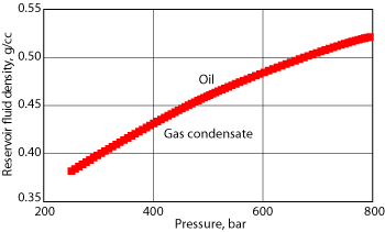
Samples from offshore wells are commonly taken in openhole by a Wireline Formation Tester (WFT) to save rig time and reduce environmental impact from a Drill Stem Test (DST). Selected sampling intervals with good permeability and hole quality increase the chances for successful WFT sampling. The hydrocarbon column height may indicate whether a compositional change with depth is likely and whether it is important to sample several intervals. Sampling should take advantage of the bubble point gradient (typically 0.2-0.4 bar/m), where the fluid is close to saturation. The pressure gradient in the hydrocarbon column and the reservoir conditions will identify the reservoir fluid, Fig. 1.
 |
|
Fig. 1. Hydrocarbon column pressure gradient and reservoir conditions will identify the reservoir fluid.
|
|
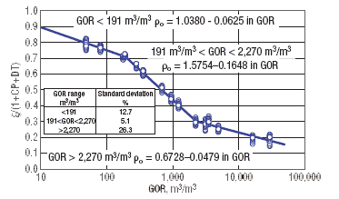
The degree of undersaturation may be evaluated using correlations. The correlations in Fig. 2 give a fairly accurate estimate for the Gas-Oil Ratio (GOR) and can be used to predict PVT properties. Wireline samples will not be truly representative due to difficulties with well conditioning and effective cleanup. There may also be effects on the reservoir fluid from decreased temperature near the wellbore from mud circulation. Nonetheless, WFT samples may be of sufficient quality and can save exploration cost by reducing the DSTs in a gas-condensate reservoir.
 |
|
Fig. 2. Undersaturation may be evaluated using correlations, like this graph between single phase density and single flash GOR.
|
|
WFT sample quality should be assessed on site by a laboratory unit, as these samples will be important in optimizing a DST. The logs and WFT sample help the wellsite engineer decide whether to take bottomhole samples or surface samples, and provide information that will help determine the correct well conditioning procedure. At the well’s gas-oil contact, the gas and oil columns will be close to saturation and a representative sample may be impossible to obtain in situ. If the well is perforated across the contact, the separator phases may be recombined in the laboratory to give representative samples from both sides.1
Single-phase sampling at the wellhead may be feasible for a strongly undersaturated reservoir fluid. If asphaltene deposition is an issue, it can be accessed from the saturation pressure and the reservoir fluid density.2 This will require bottomhole samples with full pressure maintenance. If the fluid is a gas condensate, the fluid’s leanness and the expected production rate will determine the best sampling technique, and whether isokinetic split-stream sampling at the wellhead is a better method than the test separator for accurate measurement of the sample recombination ratio.3-5 Partitioning tracers can also help establish an accurate GOR for surface samples.6,7 This technique provides samples and produces three-phase flowrates, while the installation of a large test separator unit is not attractive or feasible.8 Accurate measurements from the test separator during the highest flowrates of a gas condensate test may require additional equipment and special sampling procedures to correct the measured Condensate-Gas Ratio (CGR) for reduced separator efficiency.9-11
In addition to samples for PVT studies, more specialized objectives may be given. The sample volume required for some dynamic experiments may exclude sampling by Wireline Fluid Sampler (WFS) or bottomhole samples only. Larger fluid volumes will require flow to surface. Samples used for flow assurance must maintain the composition/pressure/temperature at the onset of the studied phenomena. Trace elements may be equally important and detection may require larger volumes than bottomhole samples or WFS can give.
WIRELINE FORMATION SAMPLING
WFTs may give good quality samples with a sufficient sample volume for standard PVT analyses. For gas-condensates, the volume may be too small to characterize heavy ends. The tools can also take samples with very low and controlled drawdowns and the closed pressurized sample can avoid phase separation. The main problem with WFT is the limited possibilities to clean the formation of mud filtrate, especially if Oil-Based Mud (OBM) was used. Later WFS generations have a pump-out capability and detection systems that monitor filtrate contamination, which increases sample quality in open holes.12-14
If the well has been drilled with OBM, the samples will be contaminated with base oil filtrate. The contamination level will be determined by: formation permeability and invasion depth, volume pumped from the formation before the sample is closed and the probe seal against the formation.
OBM contamination can be reduced by pumping fluid from the formation before the sample is closed. The fluid is discarded into the well. There may be limitations due to safety for high-pressure gas wells. An optical detector system can tell the relative contamination change during cleanup; it can be used to estimate the time needed to reach a reasonably clean oil sample.10
The oil’s bubble point pressure will decrease with increasing contamination and can be used for in situ determination of the relative contamination change during pumping. There will be an exponential decay in the contamination level with a pumped volume. Experience has shown that OBM contamination will increase with formation tightness. OBM contamination will be higher at a given pumped volume from a low-permeability formation. It is not feasible to obtain a clean sample from tight zones, due to the large volumes and long pumping times needed. As a rule of thumb, a 100-times increase in pumped volume will reduce the sample contamination level to the same level as from a 10-mD zone, versus a 1,000-mD zone. Cleanup is more effective if the sample can be taken from a thin, highly permeable bed with limited vertical permeability.
The use of dual packers in combination with WFTs can reduce contamination from a tight formation. Larger fluid volumes can be produced during the cleanup, and the formation cleans up differently. The exponential reduction in OBM in the produced fluid is replaced by plug-like flow.
Oil systems are less affected by OBM contamination than gas condensate, and a higher contamination level is acceptable without dramatically changing the main fluid properties. Bubble point pressure will decrease with increasing contamination and will affect the formation volume factors, density and viscosity. The effect on gas condensates depends on the relative difference in the molecular weight distribution of the OBM’s C7+ fraction and pure condensate. If the OBM contamination has higher carbon number components than in the reservoir fluid, the effect on the dewpoint pressure of the sample can be significant for a very small contamination. Thus, giving a general contamination level for a gas condensate sample is impossible. A typical OBM will have components in the carbon number range 9-25, with an average molecular mass equal to C14. The effect on the dewpoint pressure may be small, but the measured liquid dropout will be too high.
There are several techniques to determine sample contamination. In situ measurement gives only an approximate value and will be relative to the sample volume at reservoir condition. If the contamination level is known, it is possible to correct the composition, assuming that the base oil composition does not change during circulation. At moderate contamination levels (>10 wt% in stabilized liquid) it is possible to correct the PVT measurements with an Equation Of State (EOS). The technique calculates the effect for different contamination amounts and extrapolates back to pure reservoir fluid. The effect will not necessarily be linear. Measured data on the contaminated sample is corrected relative to the change from the extrapolation. Water-based mud systems are less likely to affect wireline sample quality.
It will not always be possible to obtain the true reservoir fluid composition from an OBM-contaminated gas-condensate sample. During OBM cleanup in gas-condensate wells using WFTs, three situations are possible:
- Inflowing reservoir gas may be directly miscible with OBM
- Inflowing gas may be immiscible with mud
- Miscibility between the two fluids can develop through a multi-contact process.
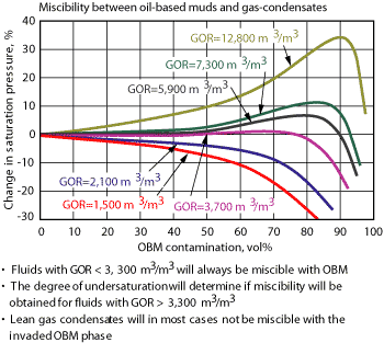
The three scenarios will influence the contamination level and the possibility of back-calculating the correct reservoir gas composition. When a gas condensate is mixed with a base oil, the dewpoint pressure can increase or decrease, determined by the molecular weight distribution of the fluids. Figure 3 shows that dewpoint pressure will increase when reservoir fluid GOR is above about 3,300. The elevation in dewpoint pressure will increase with increasing contamination and reach a maximum. The dewpoint pressure for richer fluid with a GOR below 3,300 will decrease with increasing contamination. This means that gas condensates with a GOR below 3,300 will be miscible with OBM in all proportions. The two fluid systems will move as one phase.
 |
|
Fig. 3. Change in saturation pressure with amount of OBM in reservoir fluid for different gas condensates fluids.
|
|
The situation is different for the leaner fluids (less than 3,300 GOR). Miscibility will not occur if the increase in dewpoint pressure is above the reservoir pressure in a lean gas-condensate system. The maximum point on the curves represents first contact miscibility: the lowest pressure where mud and reservoir gas are miscible in all proportions.18
Simulations show that the correct reservoir fluid composition can be back-calculated independently of contamination. The immiscible situation is very different. Components will partition between the flowing reservoir gas and OBM. The two phases move with different rates toward the well and both change with time and distance from the wellbore. Vaporized OBM in flowing gas will be different from the mud composition. The flowing reservoir gas will lose intermediates to the mud phase, which will cause the decontaminated sample composition to be too lean, giving too low a dewpoint pressure and too low a liquid dropout.18 OBM contamination will be different for each carbon group from C12 to C26. If constant contamination is assumed, negative weight fractions will be obtained for some heavier components in the mud filtrate. Decontaminated sample composition cannot be calculated from base oil composition by mass balance or by a mud tracer.
To reduce contamination, the sampled well interval should be chosen from hole quality and permeability assessment. A hole with large washouts will not give a good WFT seal. A caliper log is useful and fluid loss zones should be avoided.
The reservoir fluid sample’s contamination level for the first 12 hr will be lower, if the probe is placed in the top of the reservoir. Using water-based mud will create a similar contamination problem for formation water samples taken by WFT. A tracer like sodium thiocyanate can be added to the mud system, so the composition of the pure formation water can be calculated from a multi-ion analysis of the mud filtrate and the contaminated sample.
WFT sample quality should be assessed at surface and a decision should be made on whether the sample objectives have been reached or if further sampling is needed. If no information is available from comparable wells, the decision must be based on samples that give consistent bubble point pressures, a reservoir fluid density that is consistent with the measured pressure gradient and acceptable OBM contamination.
Saturation pressure for gas condensate is more difficult to measure on site and will not be readily available. Only the contamination level and the density may be used as evaluation criteria on site and this evaluation may not be conclusive. If a DST is to be performed, then the fluid’s nature, degree of undersaturation and GOR will be valuable for test planning and sampling.
DST SAMPLING
Cleanup and well conditioning objectives are to remove all fluids introduced into the well and the near-wellbore region during drilling. Conditioning should remove any altered reservoir fluid from the near-wellbore region. Cleanup consists of flowing the well to remove drilling and completion fluid, filtrate and altered reservoir fluid. Conditioning the well before sampling is important, even more so when the reservoir fluid is close to saturation at reservoir pressure. Shutting in the well to restore pressure will not necessarily change the altered fluid back to the original reservoir fluid. The initial flow will also re-establish the reservoir temperature in the near-wellbore region.
During cleanup, the well will flow at a low rate or at several increasing rates. For gas condensate, the flow’s linear velocity should exceed 1.0-1.5 m/sec at the wellhead.15 The cleanup process is monitored by measuring the producing GOR, the wellhead pressure and temperature, and by analysis of produced fluid. Chemical analysis will show when drilling fluids and mud filtrate have been displaced and a stabilized GOR will indicate that unaltered reservoir fluid is produced. Compensation for changing separator conditions must be done to compare GORs from different flow periods.
Gas condensates behave differently than reservoir oils. Experience shows that a gas condensate near saturation pressure can be produced representatively, even though the flowing BHP is below the dewpoint pressure, Table 1. During a relatively short well test, the drainage area will be small and the gas phase with condensate droplets will be produced with large linear velocities.
| TABLE 1. CGR versus flowing bottomhole pressure for a gas condensate (Pi = 358 bar, Psat = 247 bar based on the average CGR) |
 |
|
BOTTOMHOLE SAMPLING
Bottomhole samples are the nearest method to sample within the reservoir, and solid deposition loss in the flowline can be avoided. They may be taken on wireline or enclosed in a tubing-conveyed carrier, which can save rig time by eliminating a separate sampling flow. Several sampling chambers will be filled during a run. The sampling principle relies on single-phase hydrocarbon flow and is primarily suited for undersaturated reservoir oils. Single phase may not be fulfilled with fluids closed to saturation or with flow from tight formations. The well must be properly conditioned and producing with a pressure above the fluid’s saturation pressure at the point where the sampler is positioned. Below the bubble point there is no guarantee that oil and gas enter the sampler in the right proportions. The position of the water-oil and oil-gas contacts can be obtained from pressure gradients and the sampler should be positioned between them. The well should be closed or produced at a low rate during sampling and the sample should not be taken before altered reservoir fluid is completely displaced. If the well is flowing two phases during conditioning, bottomhole sampling is not recommended and the method is not recommended for lean gas condensates. Bottomhole sampling may work for rich gas condensates, where the liquid yield is insufficient to characterize the heavy ends.
Modern bottomhole samplers can control the sampling rate accurately and pressurize the sample before it is moved to surface. They are especially suitable for oils where asphaltenes may drop out during pressure reduction, but can also transfer gas condensates. For oils close to or at saturation, surface sampling techniques are more likely to give representative samples than bottomhole techniques.16
The sample’s representativity will be evaluated from the measured saturation pressure at reservoir temperature. The saturation pressure must be below the reservoir pressure. Multiple samples should always be taken. Samples should give consistent saturation pressures. The sample is suspect when the measured saturation pressure is equal to or above the flowing pressure at the sampling point. For asphaltene studies, the bubble point measurement can only be made on a small portion of the sample. Flash GOR should also be consistent with measured separator GOR during later DST flows. Test separator GOR, measured during bottomhole sampling flow, will usually not be accurate enough due to the low flowrate.
SINGLE-PHASE WELLHEAD SAMPLING
Samples may be obtained directly from the wellhead for oils and gas condensates, if the flow is in single phase. When the conditions for wellhead sampling are satisfied, this can be the most reliable, efficient and cost-effective way to sample. Normally, conditions will only be satisfied for the earlier and lower flowrates when the wellhead flowing temperature is low. Bottomhole sampling may be a better method for some gas condensates with high wax formation temperatures or for oils where asphaltene flocculation occurs.
SEPARATOR SAMPLING
Separator sampling collects an equilibrium sample from the test separator, while making accurate measurement of oil and gas production rates. Samples can be taken as soon as the well has been conditioned. Both phases should be sampled at the same time, and sampling time should be longer than test separator retention time. The two samples will be recombined in the same proportion as the measured rates, therefore, an accurately measured gas-oil ratio is important.
Sample sets should be taken from more than one flow. The sample recombination ratio should be based on a GOR analysis for all flows. All measurements should be corrected to the same reference conditions both within and between the flows. This analysis will identify two-phase flow effects that have affected wellstream composition and test separator GOR. The most valid samples will also be identified. Correction is easily made with an EOS, which can describe the relative effect of changing separator conditions. The derived GOR for the valid flows will be corrected back to the actual pressure and temperature during sampling to give the recombination ratio. This quantifies uncertainty in the measured GOR, which can be translated into the uncertainty for each component of the recombined composition.11
Flowmeters measure liquid flowrates. The mechanical meter factor will change with the production rate and a new calibration should be performed for each flow. Rate dependence of the meter factor should be established by an analysis of all calibration runs. The lower limit will be about 35 cmd. Below this value the liquid rate uncertainty will be large and strongly influence measured GOR. Lean gas condensate testing will require other means for rate measurement. Gauge-tank measurements will not provide the necessary accuracy due to low condensate production rates. The separation process will be different from the one used during meter calibration. The difference in shrinkage for the two separation processes adds uncertainties. The best method is to use isokinetic split-stream sampling at the wellhead.
All test separators have an upper gas capacity limit. At higher gas rates a fraction of the condensate inflow will be carried over to the separator gas outlet. The entrained liquid starts to be significant for the measured condensate-gas ratio when separator efficiency is reduced below 97%. Separator efficiency is the ratio between condensate collected in the separator and the total condensate feed at operating conditions. For the standard test separator (42 in. × 10 ft), this is passed at about 10,000 cmd.11 Demistors will have little effect on this capacity limit. The entrainment is caused by very small droplets and by secondary droplet generation. It is not practical to increase the test separator size to completely prevent liquid entrainment. Correct fluid description will not be possible for higher gas rates without an accurate entrainment rate measurement. Separator efficiency can be measured by a probe inserted in the separator gas outlet and by sampling the separator outlet gas isokinetically.
Separator conditions during reduced separator efficiency are very favorable for this measurement due to small droplets, high velocity and large voidage. The method will not likely succeed at low flowrates. However, at low flowrates the separator is close to 100% efficient and the amount of entrained liquid in the outlet gas is insignificant. The method is self-regulating-conditions favorable for split-stream sampling also reduce separator performance. Several methods can determine the condensate in isokinetic samples. The method used must distinguish between condensate and water.
Separator gas rate is measured by pressure drop across an orifice plate. This will be influenced by entrained liquid and will result in an over-reading of the gas rate when entrainment is high. Entrainment rate or void fraction determines the reading error and not separator efficiency.11 However, measured efficiency can be used to correct the gas rate. For undersaturated and relatively rich gas condensate, tubing-conveyed bottomhole samples may be a cost-effective alternative.
SPLIT-STREAM SAMPLING
Low wellhead temperatures can affect separator samples. Wax precipitation will affect samples and producing in the hydrate region will require inhibitor injection. A heater before the production choke will not eliminate the need for hydrate inhibitors in deepwater wells. The problem is larger for gas condensates than for oils due to the flow’s lower heat content and higher wax formation temperatures. Glycol should be chosen over methanol due to its much lower solubility for hydrocarbons. Split-stream sampling at the wellhead reduces these problems.
The technique is superior to the test separator when testing lean gas condensates.16 The method was originally developed by sampling from a single fixed probe inserted downstream of an inline mixing device and upstream of the choke manifold. By processing the sample through a small-scale separation system, accurate CGR can be obtained together with high-quality PVT samples.3,4 A mixing manifold is used to break annular flow and to distribute droplets homogeneously over the cross-section at the sampling point. However, well tests and flow loop experiments have shown that droplets will not necessarily be evenly distributed, which will affect measured CGR.
The method has been improved by using a traversing sampling probe that samples at a number of points across the pipe and allows correction for droplet and velocity distribution. The traversing probe should be used for gas rates below 500,000 cmd.11 The system has been successfully used at gas rates from 100,000 cmd up to 2.4 million cmd depending on the fluid. Measurements can also be made on site to determine if the fluid is single or multi-phase at surface; this may eliminate expensive downhole sampling.
CGR measurements at the wellhead also offer advantages where the test separator has sufficient accuracy. It provides an independent measurement of the producing CGR and a better base for determining the correct value. This technique can be used instead of the test separator, provided gas is present as the continuous phase at the wellhead.
WAX STUDIES
Petroleum wax consists mainly of saturated hydrocarbons like n-alkanes above C16, iso-alkanes and long-chained cyclics (napthenes). Wax may precipitate in the bulk fluid, be transported to the pipeline wall and adhere, or it may precipitate directly. The Wax Formation Temperature (WFT) determines wax deposition onset in a pipeline. The WFT is determined by the crude’s wax content and its solvent capacity. The solvent capacity is determined by the crude’s composition, dissolved light ends and pressure.
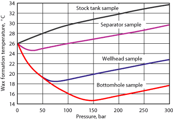
Dissolved gases are important for wax solubility, Fig. 4.19 The WFT of live oil is always lower than gas-free oil. Typically, WFT will drop by 8-10°C for each 100 bar increase in saturation pressure. WFT will increase 3-4°C for a pressure increase of 100 bar for a single phase oil. Adding gas to undersaturated oil will increase wax solubility.
 |
|
Fig. 4. Change in the wax formation temperature with pressure and origin of sample.
|
|
Pour point, the temperature needed for the oil to flow, is another property to be determined. Both WFT and pour point will increase with wax content. Below WFT, oil will depart from Newtonian behavior and give viscosities dependent on the shear rate. Rheology below WFT is needed to simulate wax deposition rates, the pigging interval, thermal insulation and to estimate the restart pressure of a flowline.
ASPHALTENE STUDIES
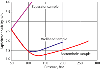
Asphaltenes present experimental challenges. They may cause formation damage, block flowlines and stabilize emulsions. Their solubility decreases as the pressure decreases in the single-phase region and is at a minimum at the bubble point. Below that point, solubility increases due to lighter ends going out of solution. Temperature influences asphaltene solubility to a very small degree and solubility behavior determines how a sample is taken, Fig. 5. The sample must be taken and kept at a pressure above the onset of asphaltene flocculation. Even though most asphaltene precipitation is reversible, the sample should be kept in single phase at a pressure above onset pressure. The dissolution process is slow.
 |
|
Fig. 5. Change in asphaltene solubility with pressure and origin of sample.
|
|
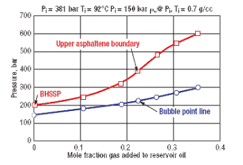
Asphaltenes will precipitate when gas is added to an undersaturated oil sample at constant pressure. The onset pressure for asphaltene flocculation will strongly increase when the light-end components increase, Fig. 6. Therefore, if separator samples are used, gas must be added at reservoir pressure and not oil to the gas.
 |
|
Fig. 6. Change in the onset pressure of flocculation by changing the composition of the reservoir oil.
|
|
EMULSION STABILITY AND RHEOLOGY
A three-phase flow of water, condensate and gas is unstable and dispersion will separate them within seconds when velocity drops. Crude oil-water systems will be partially stable at higher temperatures, and some heavy crudes form stable water-in-oil emulsions even at high temperatures.
The required data the separation time versus the watercut at operating conditions and the effective emulsion viscosity. Separation data is needed for dewatering system design and separator sizing. The effective viscosity is necessary for flowline design and capacity predictions. Separation data can be obtained from batch separation tests, where multiple phases are mixed in a choke valve before entering the separator.
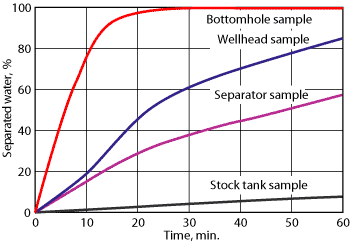
An oil’s emulsion-forming properties are dependent on several factors: solution gas content, asphaltene content and flocculation degree, wax content and precipitation, natural surfactants, fines, scale and production chemicals. Oil samples for emulsion studies should be taken as close to the pressure where the emulsion forms as possible. This requires wellhead samples. A bottomhole sample depressurized to wellhead pressure can also be used. Stabilized samples give unrealistic results, usually too conservative, Figs. 7 and 8.
 |
|
Fig. 7. Emulsion stability at 50% WC vs. the origin of sample.
|
|
 |
|
Fig. 8. Emulsion stability at 50% WC vs. the saturation pressure of the oil.
|
|
The emulsion stability determined in an atmospheric experiment must be measured with minimal air exposure. Oxidation will take place quickly and irreversibly change the sample. Aging affects the sample’s light ends, precipitation of wax and asphaltenes, and resin fraction oxidation, which causes change in bulk properties and interfacial properties. Aging creates more stable emulsions. Large-volume samples have to be protected by an inert atmosphere like nitrogen.
CONCLUSION
To base PVT properties solely on samples obtained by WFT may be costly in the long term, even though they may look attractive from a cost perspective. OBM always contaminates WFT samples. WFT samples may provide adequate samples for oil and some near-critical systems from formations with good permeability, but should not be used as the only source for gas-condensate fluid data. WFT will provide useful information for DST sampling program planning. Analytical capability should be on site to evaluate sample quality and reservoir fluid.
In theory it is possible to completely clean a reservoir zone from invaded OBM by sampling with WFTs by continuous pumping for several days. But simulation shows that it is unlikely to clean a reservoir zone within a reasonable time frame (< 12 hr), when the invaded zone extends beyond 20 cm. For situations where miscibility will not develop between the invaded OBM phase and the flowing reservoir gas, the true reservoir fluid composition cannot be obtained using WFT. The back-calculated composition of the decontaminated sample will be too lean. Errors in composition and phase properties will increase with increasing contamination.
Bottomhole sampling is preferred for undersaturated oils, near-critical fluids and rich gas condensates. Maintaining the sample at bottomhole pressure may prevent precipitation and eliminate sample transfer errors. Representative samples of gas condensates and saturated reservoir fluids are usually obtained from the test separator. At gas flowrates above 10 Mcmd, liquid entrainment in the separator gas should be measured to correct for carryover. In situations of reduced separator performance, the measured gas rate should be corrected for over-reading. However, determination of separator efficiency alone is unlikely to significantly improve data quality, if metering difficulties cause a large uncertainty in measured separator liquid rates. Condensate flowrates below 35 cmd must be measured differently. Isokinetic split-stream sampling at the wellhead is the preferred method for lean systems producing at high gas rates.
Samples for flow assurance must be taken at the conditions where precipitation starts. The sample’s composition/pressure/temperature should be restored before measurement. Stabilized oil samples cannot be used for wax and asphaltene measurements. Samples for emulsion and rheology studies have to be protected from air exposure. 
LITERATURE CITED
1 Fevang, O and C. H. Whitson, “Accurate insitu compositions in petroleum reservoirs,” SPE 28829, 1994.
2 de Boer, R. B., Leerlooyer, K., Eigner, M. and A. R. D. van Bergen, “Screening of crude oils for asphaltene precipitation,” SPE 24193, 1992.
3 Dixon, A. G. and H. K. Erbell, “Hydrocarbon fluid evaluation for hydrocarbon components,” Gas Quality, Elsevier Science Publishers, pp. 579-588, 1986.
4 Nautilus Ventures B. V., Thornton Minilab and Wellhead Sampling, 131083, 1983.
5 Witt, C. J., Crombie, A., and S. Vaziri, “A comparison of wireline and drillstem test fluid samples from a deepwater gas-condensate exploration well,” SPE 56714, 1999.
6 Nederveen, N., Washington, G. V., and F. H Bastra, “Wet gas flow measurement,” SPE 19077, 1989.
7 Petrotech A/S, Use of Sampling Apparatus for a Calibration Electronic Massflow Meters in Pipeline, US Patent P 6186 5894080.
8 Konopczynski, M. R and H. de Leeuw, “Large-scale application of wet-gas metering at the Oman Upstream LNG Project,” SPE 63119, 2000.
9 Petrotech A/S, Method and Apparatus for Isokinetic Fluid Sampling, UK Patent P 5855 2299167.
10 Petrotech A/S, A Device for Positioning of a Trottle/Mixing Body, UK Patent P 5952 2301297.
11 Hjermstad, H. P, “The significance of the test separator efficiency in testing of volatile oil and gas/condensate wells,” Lerkendal Petroleum Engineering workshop, Trondheim, Norway, Feb. 5-6, 1992.
12 Michaels, J., Moody, J. and T. Shwe, “Wireline fluid sampling, ” SPE 30610, 1995.
13 Smits, A. R., Fincher, D.V., Nishida, K., Mullins, O. C., Schroeder, R. J., and T. Yamate,“In-situ optical fluid analysis as an aid to wireline formation sampling,” SPE 26496, 1995.
14 van Dusen, A., Williams, S., Fadnes, F. H., and J. Irvine-Fortescue, “Determination of hydrocarbon properties by optical analysis during wireline fluid sampling,” SPE 63252, 2003
15 Turner, R. G, Hubbard M.G and A. E. Dukler, “Analysis and prediction of minimum flow rates for the continuous removal of liquids from gas wells,” AIME 246, 1969.
16 Towler, B. F., “Reservoir engineering aspects of bottomhole sampling of saturated oils for PVT analysis,” SPE 19438, 1989.
17 Brummenaes, H., “Field experience with gas condensate well testing without a test separator,” presented at SPE one-day seminar, Bergen, March 23, 1999.
18 Hjermstad, H. P. and B. Dybdahl, “SPE applied technology workshop,” Thailand, Feb. 20-23, 2003.
19 Hjermstad, H. P, Distinguished lecture presentation, SPE 1999-2000.
|
THE AUTHOR
|
|
|
Bjørn Dybdahl is the product line director Fluids in Expro and has 27 years’ experience in the oilfield industry. He graduated from Horten College of Engineering in Norway in 1980 with a BS degree in technical management and administration. After graduation he joined Stolt Comex International as a subsea/diving engineer. In 1984 he graduated with a BS degree in petroleum engineering from the University in Stavanger. In 1983, he founded Petrotech International. He has been a member of SPE for 25 years.
|
|
|


