HRTs offer a more robust field layout and can carry more risers than other designs.
Jean-François Saint-Marcoux, Acergy; and Robert D. Blevins, Consultant
As water depth increases, the risers’ loads on an oil-producing Floating Processing Unit (FPU) increase. Hybrid Riser Towers (HRTs) have been proposed to alleviate this issue for FPSOs and semisubmersibles. They generally fall into two main categories: monobore and multibore. ExxonMobil’s Kizomba Field in West Africa is an example of a monobore HRT. Total’s Girassol and Rosa Fields and BP’s Greater Plutonio development are examples of multibore HRTs. Both single-bore and multibore systems are effective. Nevertheless, improvements are necessary.
In deep water, riser hydrodynamic interference becomes a problem, especially for monobore HRTs. For single-line risers or riser bundles sharing parallel paths in a cross current, the upstream riser or bundle influences the movement of the downstream riser or bundle beyond previously acknowledged distances, thereby making riser interference more acute for single-bore HRTs.
Large multibore HRTs servicing large fields may lack the flexibility required by the operating company. Smaller multibore HRTs are a potential solution for the following reasons. Except for very large unfractured reservoirs, development of a field requires several well clusters, each cluster located to cover one of the reservoir horizons. These clusters are usually developed in phases, consistent with progressing geologic appraisal. Two production lines in a loop and usually one or two injection/export lines are required for each cluster. Bundling those lines is the rationale for the HRT as a drilling center.
DRILL CENTER PRODUCTION
For large oil reservoirs (typically 1 billion bbl or more), the distribution of wells maps the reservoir structure. For smaller peripheral accumulations (typically a few 100,000 bbl), a dedicated well cluster, or drill center, is required in the area accessible by a semisubmersible moving within a fixed mooring pattern. The minimum functions to produce from an isolated oil accumulation are production, injection and export.
Production can be achieved two ways. Two production lines can be arranged in a loop, both insulated to the minimum Overall Heat Transfer Coefficient (OHTC) and Cool-Down Time (CDT) required for hydrate mitigation. Both lines can be used simultaneously, or alternately for smaller flowrates. For long tiebacks and low producing rates, OHTC and CDT become more onerous. It is cost-effective to use only one insulated production line and a non-insulated service line, pre-filled with dead oil. Upon shutdown, dead oil displaces live oil, thereby avoiding hydrate formation. In either case, riser base gas lift is required to stabilize the flow in the production lines.
Injection lines can be either water injection, almost systematic in West Africa, or gas injection into the oil reservoir or a separate formation. Export lines are usually for gas and are tied back to an existing hub, as in the GOM, or connected to an existing or future gas gathering network. Generally, the sizes of the production line and the injection line are similar, whereas the export line may vary in size.
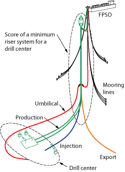
As a summary, a minimum riser system for a drill center will require two production lines and associated risers, one or two injection/export lines and associated risers and one umbilical, Fig.1.
 |
|
Fig. 1. A minimum riser system for a drill center requires two production lines and risers, one or two injection/export lines and risers and one umbilical.
|
|
DRILL CENTER HRT
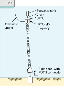
From its experience with two major projects in West Africa, Acergy has defined a basic configuration for a riser tower (Fig. 2) including:
- Flexible jumpers
- Upper riser termination
- Riser bundle
- Lower riser assembly
- Foundation
- Bottom spools
- Umbilical.
 |
|
Fig. 2. The basic HRT configuration includes flexible jumpers, upper riser termination, riser bundles, lower riser assembly, foundation, bottom spools and umbilical. (Patent pending)
|
|
The umbilical could technically be made part of the riser system. However, on past projects, this idea was not implemented because an extra hydraulic and electrical connection was required. The additional connection reduces the overall control system reliability.
RISER BUNDLE
Because the riser bundle includes three or four risers, the following arrangements are possible:
- Three in-line risers
- Three risers at 120° with a central core pipe used for structural purpose1
- Four risers in line
- Four risers at 90°
- Three lines at 120° with a central core for fluid transfer.
The in-line configurations are expected to be more prone to galloping.2 Model tests are required to assess the critical velocity for galloping of an HRT with an in-line arrangement.
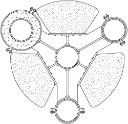
An arrangement with a central core and three lines at 120° has the flexibility of accommodating three or four lines. Also, the arrangement is more symmetrical and less prone to galloping, Fig. 3. A triangular arrangement will be considered during the rest of the article.
 |
|
Fig. 3. A symmetrical arrangement with a central core and three lines at 120° can accommodate three or four lines and is less prone to galloping than in-line.
|
|
WAKE INTERFERENCE
When a downstream riser falls in the wake of an upstream riser, the downstream riser is subject to lift and reduced drag, which can lead to wake instability. Riser movement may lead to fatigue damage and clashing in the case of small initial spacing. The minimum spacing between individual risers becomes a challenge, especially for field developments based on a turret-moored FPSO.
HRTs are only a few degrees off from the vertical axis, since they are kept under tension, usually by a buoyancy tank. Section 4.3 of DNV-RP-203 clarifies that “possible wake instabilities shall be addressed if the quasi-static shielding analysis reveals hydrodynamic interaction effects along a significant part of the risers.”3
Wake instability has been investigated for a cylinder in a wake.4 The theory has been applied to interference between flexible jumpers at the top of an HRT.5 The same theory is obviously applicable to vertical cylinders such as monobore HRTs or multibore HRTs. Laboratory measurements performed at the Scripps Institution of Oceanography up to 80,000 Reynolds validate the theory.6 The strong influence of riser interference for parallel risers is also acknowledged by Fontaine et al.7
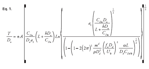
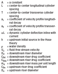
The critical curve for wake instability defines the zone of the layout where the movement of the downstream riser becomes unstable. The formula is given by Eq. 1, Table 1.
| TABLE 1. Definition of terms |
 |
|
The extent of the envelope in the direction of the current (T = 0) is obtained by setting the argument of the logarithm to 1. This provides an implicit relation for the minimum distance to limit the interaction between two risers, Eq. 2.

EXAMPLES
A typical field development in West Africa has the following characteristics:
- Water depth of 1,500 m (4,900 ft)
- An FPSO of 2 million-bbl capacity with a bow-mounted turret, permanently moored
- Three drill centers with 12-in. lines
- OHTC for production lines equals to 2.5 W/m2K, (0.44 Btu/hr-ft2 °F) based on ID
- Buoyancy tank at 100 m (330 ft).
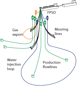
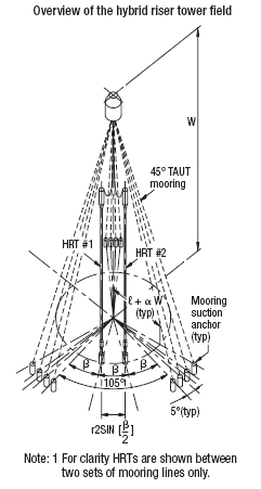
The layout is driven by the turret mooring, typically three sets of four mooring lines at 120º and the length of the FPSO. The base of the HRT would lie outside of the FPSO weathervaning circle. For West African conditions, the circle is about 375 m (1,200 ft), Fig. 4.
 |
|
Fig. 4. The overall arrangement has an FPSO with wells from two drill centers.
|
|
The robustness of a riser system for future developments is given by its capacity to accommodate a large number of risers with a minimum of installation issues, as they are progressively installed, Fig. 5.
 |
|
Fig. 5. The layout of closely spaced HRTs around an FPSO turret lies outside the weathervaning circle.
|
|
The purpose at an early stage is to discriminate between risers systems that may behave similarly. Using Eq. 1, it is possible to compare three risers systems: monobore HRTs installed by J-lay, monobore HRTs installed by towing and HRT as a drill center.
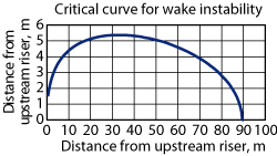
Monobore HRTs installed by towing have distributed buoyancy over their length, which provides slightly different behavior. A typical curve for the wake instability critical curve of a monobore HRT shows that the distance of wake instability is significant; it extends very far in a relatively flat, somewhat elliptical area, Fig. 6. The curve was developed using: U0 = 0.54 m/s, CDu = 1.2, CDd0 = 1.2, Du = 0.54 m, Dd = 0.54 m and fn = 121 s.
 |
|
Fig. 6. A typical wake instability critical curve for a monobore HRT shows that instability extends very far in a flat, elliptical area.
|
|
The curve defines the area where the movement of the downstream riser in the direction of the wake exceeds 10% ( = 0.1) of the initial distance between the upstream and downstream risers. Being outside of the curve does not mean that there is no movement. The value for the current is the mean velocity of the 100-yr current over the length of the riser. = 0.1) of the initial distance between the upstream and downstream risers. Being outside of the curve does not mean that there is no movement. The value for the current is the mean velocity of the 100-yr current over the length of the riser.
More detailed analyses are required to assess the real fatigue damage that would be suffered by the downstream HRT. The actual damage depends on the current distribution (vertical and with time) and the design of the HRT.5
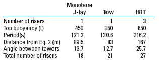
Table 2 summarizes the findings. A drill center configuration can accommodate a significantly larger number of risers than a monobore configuration.
| TABLE 2. Riser comparison for West Africa conditions |
 |
|
For the GOM, a typical ultra-deepwater field development has the following characteristics:
- Water depth of 2,500 m (8,200 ft)
- An FPSO of 700,000 bbl capacity with a bow-mounted turret, permanently moored
- Three drill centers with 8-in. lines
- OHTC for production lines equal to 3.4 W/m2K (0.6 Btu/hr ft2 °F) based on ID
- Buoyancy tank at 200 m (650 ft).
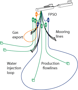
Turret mooring drives the layout, typically three sets of four mooring lines at 120° and the FPSO length. The HRT base would lie outside of the FPSO weathervaning circle of about 325 m (1,070 ft), Fig. 7.
 |
|
Fig. 7. In the GOM, the HRT base would lie outside of the FPSO weathervaning circle of about 325 m (1,070 ft).
|
|
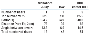
Again using Eq. 1, it is possible to compare three riser systems: monobore HRTs installed by J-lay, monobore HRTs installed by towing and HRT as a drill center. The critical curve is defined for a movement of the downstream riser of 10% of the initial distance between them. However, the GOM’s current is taken as the mean value of the 100-yr submerged current over the length of the riser. This approach is conservative due to the low occurrence of the submerged current. Using the 100-yr GOM current would provide a larger number of risers, but it would not change the ranking of the three riser systems, Table 3.
| TABLE 3. Risers comparison for GOM conditions |
 |
|
CONCLUSION
Three riser systems for a field development consisting of several drill centers have been described: J-lay monobore HRTs, towed monobore HRTs and HRT drill centers. Based on the impact of wake instability on risers system with a parallel path, there is a significant advantage to using an HRT as a drill center, because of the number of risers that can be accommodated for a given field.
A similar trend is found for both the GOM and West Africa. The riser system ranking is: HRT as a drill center, towed monobore HRT and J-lay monobore HRT.
An HRT as a drill center provides two main advantages: the same reliability as monobore HRTs in a single offshore installation campaign and a more robust field layout. Clearly, a field development may also make simultaneous use of the various HRT types. 
ACKNOWLEDGEMENT
The authors thank Acergy for supporting this work, and Arturo Passanem and Cynthia Carter for preparing the manuscript. This article was derived from OMAE 2007-29289 presented at the 26th International Conference on Offshore Mechanics and Arctic Engineering, June 10-15, 2007, San Diego, California.
LITERATURE CITED
1 API RP 2RD, 1998, Design of Risers for Floating Production Systems (FPS’s) and Tension Leg Platform (TLP’s), 1st edition, p. 6.
2 Abbott, I. H., 1949, Theory of Wing Sections, McGraw-Hill, New York, p. 113, eq. 6.2.
3 DNV-RP-203, 2005, “Riser Interference,” (industry hearing under progress), p.15.
4 Blevins, R. D., “Forces on and stability of a cylinder in a wake,” ASME J. OMAE, 127, pp. 39-45.
5 Blevins, R. D., Jacob, P., Saint-Marcoux, J. and M. Wu., “Assessment of flow-induced jumper interference for hybrid risers,” ISOPE 2006-381, 2006.
6 Blevins, R. D. and M. Wu, “Experimental investigation of interference between upstream and downstream cylinders in a current,” OTC 18529 presented at the Offshore Technology Conference, Houston, April 30-May 4, 2007.
7 Fontaine, E., Morel, J-P., Scolan, Y. M. and T. Rippol, “Riser interference and VIV amplification in tandem configuration,” ISOPE, Vol. 16, 2006, pp. 33-40..
|
THE AUTHORS
|
|
|
Jean-François Saint-Marcoux earned a mechanical engineering degree from Ecole Centrale de Lyon, an MSME from California Institute of Technology and a Docteur-Ingenieur degree from Paris VI University. He has over 30 years of offshore industry experience and ran the Acergy Girassol, Bonga, Erha and Greater Plutonio Expert Committees. He now runs the committees of Frade, Block 15 and Pazflor. Saint-Marcoux is Group Conceptual Engineering Manager with Acergy, based in Houston.
|
|
|
|
Robert Blevins earned a degree from Carnegie Tech, and a PhD from California Institute of Technology in 1974. He has written three books and 30 papers, and has 30 years of professional experience working with flow-induced vibration. He teaches ASME Professional Development Course PD146.
|
|
|


