Wear and friction of hard-faced claddings
Vol. 229 No. 3 DRILLING Wear and friction of hard-faced claddings Block-on-ring test configuration shows that cladding microstructure in new developmental alloys effects both cladding and casing wear. John Truhan ,* University of Tennessee, Ravi Menon, Frank
Block-on-ring test configuration shows that cladding microstructure in new developmental alloys effects both cladding and casing wear.John Truhan,* University of Tennessee, Ravi Menon, Frank LeClaire, Jack Wallin, Stoody Co., Jun Qu and Peter Blau, Oak Ridge National Laboratory Hard-face claddings are used for banding drill shafts that rotate against well casings while lubricated by drilling mud. To maximize component life, the tribosystem, defined as materials in sliding contract with lubricants or films in the interface, should have the lowest total system wear, and the lowest friction possible in order to minimize drilling power requirements. Blocks representing a variety of hard-face claddings were slid against rotating rings of AISI 4140 casing material and lubricated by simulated drilling mud that consisted of a slurry of silica sand, clay and water. Currently used alloys and several candidate developmental compositions were used as cladding specimens. The results showed an excellent correlation between the friction coefficient and the wear, by weight loss, of both cladding and casing alloys. There was also a good direct correlation between wear of the cladding and wear of the casing. Claddings with finer grain sizes and finer, more uniformly distributed hard carbides had higher hardness and produced lower wear on both cladding and casing counterface. The complex mechanisms involved with three-body wear and friction in interfaces lubricated by slurries present a challenge for further study. BACKGROUND Deephole drilling in extremely harsh environments presents a challenge in the choice of drilling materials used for mining applications. Low wear is desirable to increase both shaft and casing life while reducing maintenance. Low friction is desirable to reduce the energy needed for drilling. Extensive development efforts to reduce wear and friction have been undertaken on hard-faced claddings for drill shafts. However, any evaluation of the cladding alloys must also include an evaluation of the response of the counterface, i.e., the well casing. A combination that produces the least wear and friction of the tribosystem would be the optimum choice of materials. Each of the several industry-recognized tests for evaluation of cladding and casing materials lubricated by a drilling “mud” slurry has advantages and disadvantages. The DEA-42 Maurer Test is a proprietary test for casing wear and requires the use of large specimens. This test is difficult to perform and more expensive than other tests. The ASTM G65 dry-sand/rubber wheel test1 and the ASTM G105 wet sand/ rubber wheel test2 for abrasion resistance do not allow for the influence of a metal counterface, although they are less expensive and easier to apply. In previous work, a pin-on-disk test was used to measure friction between various cladding alloys and AISI 4140 counter face representative of casing material under slurry-lubricated conditions.3 The degree of wear could not be measured accurately due to production of a shallow, diffuse wear scar, which was formed by the relatively large particles of silica in the slurry creating rapidly varying interfacial conditions, and the relatively small area of contact. While there have been numerous publications on slurry erosion and the effects of drilling mud,4-6 little has been published concerning the effects of abrasive slurries on friction. This study uses a new block-on-ring procedure, enabling both friction and wear measurements to be collected, to expand on the previous work that uses a pin-on-disk test.3 Conditions were selected so that tests could be run in a short time, but produce enough wear to use weight loss as an unambiguous measure. The objectives of this study were:
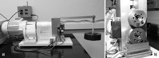
EXPERIMENTAL PROCEDURES Commercially available equipment was used to perform the block-on-ring tests, Figs. 1a and 1b. Figure 1a displays an overall view of the apparatus, showing the dead-weight loading visible on the right. Figure 1b displays the mounted test coupons. The 12.7-mm-wide slider block with hard-face cladding is mounted on the upper holder and the rotating ring, representing the casing alloy, is mounted below it. A reservoir below the ring contains the slurry. The lower part of the ring picks up slurry as it rotates and carries it to the interface, while a metal shield, not shown, prevents slurry from splashing out. Friction force is measured with a load cell and the data are collected using a computer data acquisition system. Table 1 summarizes the test parameters. The load and test duration were selected to produce enough wear on both the block and ring to use weight loss as the wear metric.
Table 2 shows the composition of the slurry, which was a simulated drilling mud. The clay was first mixed in the water until thoroughly dispersed, and then silica was slowly added with continued stirring, in order to get the most uniform distribution. The slurry was agitated prior to filling the reservoir because settling between tests was inevitable.
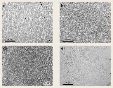
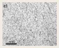
The 60-mm-diameter rings of AISI 4140 steel tempered to a hardness of 271 BHN were used to represent the casing material. The block claddings represent both currently used alloys and several developmental alloys. A block of 4140 steel similar to the ring was also tested as a reference couple. Care was taken to orient the block so deposition direction matched that for service conditions because there is directionality of the microstructure of the cladding due to the deposition process. Table 3 summarizes the nominal compositions of various claddings tested. Alloys identified as 1P, 15P, 17P, 18P and 19P are current cladding materials. The remaining cladding alloys, 12P, 13P and 14P, were developed by the Stoody Co. for wear performance and ease of application. All of the cladding alloys, except Alloy 17P, have in a martensitic matrix with or without dispersed secondary carbides and borides. Alloy 17P is the only stainless steel in the test program which consists of a semi-austenitic matrix with a dispersion of chromium bodies. Representative microstructures of test alloys are shown in Figs. 2a-e. Alloy 1P is a martensitic tool steel hardfacing deposit, Fig. 2a. In addition to martensite, there is some retained austenite. Alloy 19P has a similar matrix along with dispersed-titanium carbide, Fig. 2b. Alloy 12P is similar to Alloy 19P, but to produce better wear performance, some of the titanium has been replaced with niobium and molybdenum, Fig. 2c. In the developmental Alloy 14P, the titanium has been completely replaced with niobium, molybdenum and tungsten, Fig. 2d. Although this replacement results in a small increase in the total system wear, applicability of the hard-facing is significantly improved due to reduction of titanium in the wire consumable used to deposit it. Alloy 17P was the only stainless steel hard-facing tested, Fig. 2e. The microstructure of Alloy 17P shows acicular chromium borides in a semi-austenitic matrix. In contrast to the alloys 19P, 12P and 14P, there is no finely dispersed secondary micro-constituent in Alloy 17P.
RESULTS AND DISCUSSION Figure 3 summarizes friction and wear results from this investigation. Not surprisingly, the highest friction and wear occur for the reference couple: self-mated 4140. As expected, amount of wear for clad blocks was reduced by almost an order of magnitude compared to the self-mated couple. Wear reductions were on the order of 20-40% for the rings which was not quite as dramatic as for the blocks. The friction coefficient for all cladding combinations exhibited little variation and is only slightly lower than for the self-mated couple. The properties of the slurry, with its significant amount of entrained silica dust, likely controlled frictional behavior. Harder materials probably allowed less silica particulate indentation, and therefore somewhat reduced the frictional drag in the interface.
Block and ring wear. As stated previously, it is important that the wear of the casing not be accelerated by the wear-resistant, hard-face claddings. Figure 4 shows the sum of wear on both specimens as the total system wear for the various cladding combinations. Ring wear contribution accounts for most of the variation in total system wear, demonstrating the importance of not focusing solely on cladding wear. Certain combinations perform substantially better than others. The lowest total tribosystem wear was achieved by couples using the 12P and 19P claddings, with 12P achieving lowest total wear with slightly less than 0.04 g weight loss.
A distinct relationship between friction and wear was observed, which was irrespective of composition or microstructure, Fig. 5. This relationship implies that hard-face claddings sliding against slurry-lubricated casing material behaved in a mechanistically similar manner. More material was removed as more energy was available to do frictional work.
Slurry nature effects wear. Figure 6 data indicate an approximate trend between block wear and ring wear. Lower block wear tended to accompany lower ring wear. The highly abrasive nature of the slurry may explain this trend. The silica dust in the slurry is much harder than either surface, and therefore can cause wear in both the block and the ring, but the relative amount of wear may differ. When a harder material rubs against a softer one, the degree that the harder material causes wear in the softer is questionable. From a quasi-static point of view, the relative hardness of the two softer surfaces should affect the degree to which a harder particle trapped between the softer surfaces will penetrate either of those surfaces. Table 3 displays the ratios of the HRC of the block relative to the ring.
However, that quasi-static argument does not take into account that in slurry wear, hard particles are passing through the interface entrained within a viscous fluid, tumbling, and cutting. Plowing or cutting occurs only when a particle or agglomerate is advantageously aligned and when a sufficient load can be transferred to the particle. If one of the surfaces is ductile enough that hard particles become momentarily embedded, there could be two-body and three-body abrasion occurring. Oxidation of test specimens during the time between testing and observation obscured the finer wear scar features, which may explain why post-test optical examination did not reveal any silica embedded into the 4140 rings. Additional studies by electron microscopy would have been desirable, but the scope of the project did not allow them. Interestingly, there were no evident correlations between the cladding hardness and either the friction coefficient, block weight loss or the ring weight loss. This result is somewhat surprising since the cladding hardness for the various materials covers a wide range of variation, from about 40 to 66 HRC. Cladding hardness alone was evidently not a good predictor of wear or friction behavior in this particular tribosystem, although the fundamental reasons for these results remain unclear. Notably, the friction coefficients measured in this study are roughly a factor of two higher than previously measured using a pin-on-disk test.3 The higher surface area and converging linear contact of the block-on-ring tests likely allows for a more representative slurry composition to be confined within the interface. The small surface area of the rounded pin tip would not be expected to trap much silica dust, especially the larger particles. Lack of particle entrainment in the pin-on-disk tests may be due to the values of their frictions coefficients, which for slurry-lubricated pin-on-disk tests were comparable to those run with water lubrication alone (0.33 compared to 0.35). Microstructure importance. The cladding microstructure and tribological performance appear to be connected , as claddings with a finer, more uniform grain size and a uniform dispersion of carbides had better friction and wear performance than claddings with more heterogeneous microstructures, Figs. 2a-2e. Figures 2b, 2c and 2d represent the claddings that had better overall performance, and include both developmental claddings and one commercial cladding. Despite their differences in hardness due to different carbide types, their microstructures are similar. In contrast, cladding alloys represented in Figure 2a and 2e display coarser, more heterogeneous microstructures, with correspondingly poorer friction and wear performance. These results, though not unexpected, are in contrast with previous results,3 which demonstrates the difficulty with using the pin-on-disk test with slurry lubrication. Figures 7 and 8 display typical wear scars on both the block and ring for high and low wear couples. Figure 7 displays self-mated 4140 steel with severe abrasive wear, consistent with the high wear measured for that combination. By contrast, the morphology of the wear scar for a clad block showing low friction and wear shows abrasive wear, but with a smaller scar area and much finer parallel scoring, especially on the block side, Fig. 8.
CONCLUSIONS The block-on-ring test configuration is relatively simple to use, and can be helpful in evaluating the friction and wear of drill-shaft cladding alloys against a casing alloy in slurry-lubricated conditions. Also, block-on-ring results produced more quantitative wear measurements than were possible using pin-on-disk tests on similar materials. Using the block-on-ring test, a very good correlation between friction and wear of both the cladding and casing materials in slurry-lubricated conditions was established. Also, there was a good correlation between the cladding wear and casing wear, but there was no apparent correlation of the cladding hardness alone with either cladding friction or wear, although harder claddings produced less casing material wear. The composition of the claddings was also important as a fine, uniform cladding microstructure produced lower friction and wear than coarser microstructures. In general, the newer developmental cladding alloys performed better than most of the commercially available claddings. Complex interactions between fluid dynamics, fluid chemistry and instantaneous mechanical contact are difficult to understand, and go far beyond the scope of this article. However, the results of this work suggest that selection of materials can influence sliding friction between cladding and casing materials, as well as slurry characteristics, and that total tribosystem wear can be reduced by judicious selection of material compositions. *Truhan now works for Caterpiller, Inc. ACKNOWLEDGMENT This research was sponsored by the Assistant Secretary for Energy Efficiency and Renewable Energy, Office of FreedomCAR and Vehicle Technologies, as part of the High Temperature Materials Laboratory User Program, Oak Ridge National Laboratory, managed by UT-Battelle, LLC, for the US Department of Energy under contract number DE-AC05-00OR22725. LITERATURE CITED 1 ASTM G 65-04, “Standard test method for measuring abrasion using the dry sand/rubber wheel apparatus,” Annual Book of Standards, Vol. 03.02, ASTM International, West Conshohocken, Pennsylvania.
|
|||||||||||||||||||||||||||||||||||||||||||||||||||||||||||||||||||||||||||||||||||||||||||||||||||||

- Coiled tubing drilling’s role in the energy transition (March 2024)
- Using data to create new completion efficiencies (February 2024)
- Digital tool kit enhances real-time decision-making to improve drilling efficiency and performance (February 2024)
- E&P outside the U.S. maintains a disciplined pace (February 2024)
- Prices and governmental policies combine to stymie Canadian upstream growth (February 2024)
- U.S. operators reduce activity as crude prices plunge (February 2024)

