The new developments include wireline and while-drilling depth-correction methods; telemetry technology; acoustic, nuclear, resistivity and production logging devices; formation testers; and surface logging technology and techniques.
Stephen Prensky, Consultant, Silver Spring, Maryland
Recent advances in logging and formation evaluation include a new through-casing resistivity tool; HPHT tools; while-drilling directional propagation and electrode resistivity, wireline and while-drilling resistivity logging; formation testing; production logging; LWD acoustic, nuclear and seismic-while-drilling; and a portable NMR probe.
A number of technical papers published on well logging and formation evaluation during the past year-as well as workshops, forums and symposiums sponsored by oilfield professional associations-provide insight into the topics of highest interest to the industry. In 2007 these included:
- Directional resistivity logging tools (SEG-SPWLA workshop, September 2007)
- High-angle and horizontal wells (SPWLA India Regional Conference, March 2007)
- Core-log integration (SPWLA Topical Conference, May 2007)
- Anisotropy and fractures (SEG, special issue of The Leading Edge, September 2007)
- Carbonate reservoir characterization (SPWLA Topical Conference)
- Geomechanics (SEG, special issue of The Leading Edge, May 2007)
- In-well optical sensing (SPE Applied Technical Workshop; EAGE Workshop).
Although not all of these topics of interest resulted in advancements in logging and formation evaluation technology in 2007, we can anticipate advancements in all these areas in the near future.
WIRELINE LOGGING
The past year saw a host of new wireline logging tools and improvements in existing tools, as wells as new studies of interest to wireline operators.
Depth accuracy. The service companies have shown great interest in improving the depth values provided to their customers, and this interest continues to generate new methods for improving the accuracy and reliability of these critical data. Schlumberger and Statoil presented a wireline-depth-correction technique that uses a finite-element model to estimate an “environmentally corrected” wireline depth. The model computes a tension profile for discrete borehole segments, taking into account borehole length, deviation, azimuth, temperature, pressure and curvature. The modeled profile is compared to the actual tension recorded during the log run, and the sum of differences for all segments provides the required depth correction. Several years of field tests have demonstrated that this method can reduce the depth differences between LWD and wireline logs by an order of magnitude.1
On the LWD side, a paper presented at the SPE annual conference discusses the significant improvement in dip determination from LWD images obtained using the dynamic LWD depth-correction method discussed last March in this article.2
Logging cable. Institut Français du Pétrole (IFP) recently developed a semi-rigid logging cable that is stiff enough to push logging tools downhole in high-angle and horizontal boreholes but flexible enough to be wound on a winch drum.3 The cable is composed of a resin/glass-fiber composite that is continuously extruded around an inner core of electrical or fiber optic lines. The diameter of tested cables ranges from 9/16 in. to 13/16 in. (14-20 mm).
Multicomponent and triaxial devices. These devices were introduced 10 years ago to improve thin-bed evaluation by resolving and quantifying resistivity anisotropy. They provide Rh and Rv values, and now advanced processing allows determination of formation dip and strike (azimuth). Reviews of the state-of-the-art equipment and operator experiences with them were presented in two technical papers presented at the SPWLA annual symposium.4,5 One paper concluded that a lack of understanding of the added value these tools bring to formation evaluation has prevented wider acceptance of the technology.
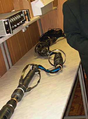
Through-casing resistivity. A novel through-casing resistivity tool designed by Weatherford is currently undergoing field tests.6 Unlike the rigid-body designs in current use, this tool has a flexible design: The various components (electronics, transmitters and receivers, and a weighted sinker bar) are independent units connected by cables, Fig. 1. The measurement sonde consists of 1.2 m of mechanical cables, hoses and electrical cables that connect the measurement and current-emitting electrodes. The components are assembled before rig-up. Tool measurement is conducted in stationary mode at about 3.6 min. per station, typically at 1-m intervals for an effective logging speed of 530 ft/hr (162 m/hr). Testing results demonstrated good correlation with both induction and spherically focused resistivity logs.
 |
|
Fig. 1. The Weatherford through-casing resistivity tool in the laboratory.6
|
|
Nuclear source replacement. A recent report by the National Petroleum Council voiced a serious concern within government and industry that conventional industrial and commercial chemical radiation sources could be used by terrorists to create a “dirty bomb.”7 In particular, this concern includes sources that contain more than 1 g of highly radioactive materials, e.g., the americium-beryllium sources used in neutron-logging devices.
Several studies, including one conducted by the National Academies, have considered where and how these sources can be replaced by non- or less-radioactive alternatives.8-10 In some devices, chemical sources are being replaced by non-radioactive, pulsed-neutron generators; e.g., Schlumberger’s Ecoscope (discussed here in March 2006) uses electronic pulsed-neutron generators in place of chemical sources. Californium-252 offers a chemical replacement. This isotope is a strong neutron emitter with three orders of magnitude less radioactivity than americium-beryllium sources, and poses internal health hazards only if ingested or inhaled, not by skin penetration.8 Pathfinder’s new LWD porosity tool (discussed under “Logging while drilling” below) is the first commercial logging device to use the low-radiation californium-252 source.11
Hostile-environment tools. Conventional wireline logging tools are typically rated to 350°F (177°C) and 20,000 psi (138 MPa), and LWD tools to 300°F (150°C) and 20,000-25,000 psi (138-172 MPa). Several service companies have recently introduced new wireline and MWD/LWD tools to meet the high-pressure and high-temperature challenges in recent ultradeep drilling. Schlumberger introduced a quad-combo wireline toolstring rated to 500°F (260°C) and 30,000 psi (207 Mpa).12 Weatherford’s latest LWD tools are rated to 330-360°F (165-180°C) and 30,000 psi (207 MPa).13 Pathfinder’s Survivor HPHT LWD tools are rated to 350°F (175°C) and 25,000 psi (172 MPa).14 This tool suite includes compensated propagation resistivity, neutron-porosity, MWD/gamma ray and annular pressure.
Gamma-ray discrepancy. A Monte Carlo simulation study was conducted at the University of Texas to understand why wireline and LWD gamma-ray logs can read different values in the same well. Results indicated that tool design is not a source of significant difference. Rather, the cause appears to be insufficient correction when borehole and mud conditions differ from those used in the tool calibration.15
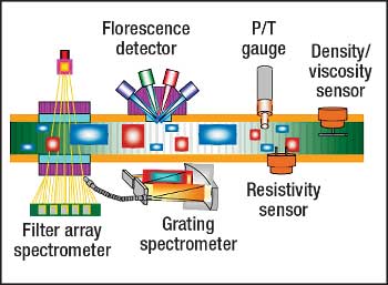
Formation testing. Schlumberger introduced a formation tester that makes an in situ determination of fluid density and viscosity, in addition to improved downhole fluid analysis.16,17 A grating spectrometer has been added to the existing filter-array spectrometer to provide complementary measurements of the absorption spectrum of formation fluids in the visible and near-infrared spectrum.
These complementary measurements have extended the hydrocarbon-composition range of the tool from four carbon groups to five. These additional data improve accuracy and reliability in the quantitative fluid analysis. Fluid composition and estimates of the gas-oil ratio are derived from this data. A fluorescence detector measures reflected and fluorescence emissions from fluid in the flowline, Fig. 2. The emissions data indicate the presence of gas bubbles and liquid dropout, which in turn is used to identify reservoir fluid type and phase. Differences in the absorption spectrum among the reservoir fluid, filtrate and mud (oil- or water-based) are used to estimate sample contamination.
 |
|
Fig. 2. Schematic of Schlumberger’s new downhole fluid analyzer tool.16
|
|
The new density/viscosity sensor uses the resonance frequency and quality factor of a vibrating beam to measure density and for viscosity determination. Lab tests show the absolute accuracy of the density measurement to be better than 1%, and the relative accuracy of the viscosity measurement to be better than 10%. The conventional resistivity and temperature sensors used on formation testers have been integrated into the fluid analysis. The tool also includes the pH sensor discussed in this article in March 2006.
PRODUCTION LOGGING
Two new logging systems released last year are expanding the usefulness of production logging.
Leak detection. A new ultrasonic through-tubing noise log, able to locate casing leaks through multiple strings of tubulars, has been developed through a joint venture of TecWel and ConocoPhillips.18,19 Noise logs locate casing leaks by detecting changes in audible or ultrasonic frequencies generated as the fluid flow through the hole becomes turbulent due to the pressure accompanying flow through a constricted opening. The tool uses a piezoelectric sensor that produces small-voltage responses proportional to the acoustic signal (signature) generated at the leak point.
The Well Leak Detector (WLD) tool can detect and locate leaks as small as 0.25 gal/min in tubing and casing with an accuracy of 3 ft, from inside tubing and while operating at conventional logging speeds. Once a leak is indicated, stationary measurements are made above and below the suspected leak point to confirm the location.
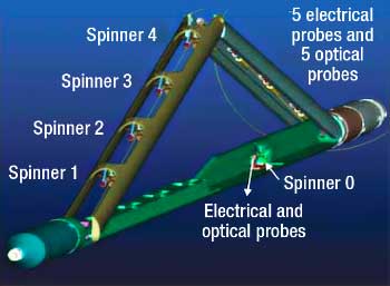
Flow in high-angle wells. Schlumberger’s Flow Scanner, a compact production-logging system, is designed to evaluate gravity-separated multiphase flow in high-angle and horizontal wells.20 Three sensor arrays are mounted on two retractable arms, Fig. 3.21 One arm contains four mini-spinners, while the other arm contains five sets of optical and electrical probes. An additional spinner, together with a set of probes, is mounted on the tool body to measure fluid properties at the low side of the borehole.
 |
|
Fig. 3. Sensor configuration of Schlumberger’s new production logging tool for high-angle and horizontal wells.21
|
|
The low-frequency electrical probes measure fluid impedance to discriminate oil from water and water holdup. The optical sensors use the fluid optical index for gas detection. The mini-spinners determine flow velocity at different levels along the vertical borehole axis to provide a flow profile. The retractable arms also serve as a caliper to enable measurement of cross-sectional area, a parameter required to calculate flowrates. The 1.68-in. (43-mm) tool is 16 ft (4.9 m) long and combinable with other cased-hole logs. It can be run on wireline, coiled tubing, or as part of a tractor system in boreholes ranging from 27/8 in. to 9 in. (73-229 mm).
LOGGING WHILE DRILLING
Recent LWD developments include new real-time telemetry methods, azimuthal resistivity tools, seismic-while-drilling devices and others.
Telemetry. A variety of real-time LWD telemetry systems is currently available. The most widely used is mud-pulse telemetry; although this method has the lowest data-transmission rate (≤ 15 Bits per second (BPS)), it is reliable at large depths. Electromagnetic telemetry (< 15 BPS), available only in land wells because it transmits through the earth, has recently found a niche in underbalanced drilling, where the use of compressible drilling fluids prevents the application of mud-pulse technology.22-24 Halliburton’s acoustic telemetry system (20-100 BPS), discussed in this article in March 2006, offers an additional telemetry option in underbalanced drilling;25 XACT Downhole Telemetry is developing a second commercial acoustic system.26 The Intellipipe wired-pipe system has the highest data-transmission rate of any commercial telemetry system (57,600 BPS).27
Two ultra-high-speed downhole data transmission systems (≥ 1 million BPS) have been developed but have not yet entered commercial service. The first is an inexpensive downhole fiber optic telemetry system (1 million BPS) developed by Sandia National Laboratory in 2002. It uses disposable fiber optic cable run down the drillpipe; however, it doesn’t seem to have been adopted for logging purposes.
The prototype of another wired-pipe system, designed to produce a bidirectional data rate of 1 million BPS in ordinary drillpipe, has been developed as a joint venture of two Italian companies, Eni and Tecnomare.28 This system, currently undergoing field tests, uses an in-pipe vehicle, containing a cable cartridge, to lay a thin (2.4-mm) custom-made twisted-pair electrical wire inside the drillpipe as pipe is added to the drillstring.
Directional-survey reliability and QC. Following up on the topic of the SPE Well Positioning Technical Section (discussed last March in this article), a recent report documents weaknesses in current directional-survey QC practices and proposes a new set of minimum requirements for survey validation.29
Azimuthal resisitivity. Deep-reading directional resistivity devices represent the latest trend in geosteering services. The combination of deep-reading measurements and azimuthal sensitivity provides earlier and more accurate indications (including both distance and direction) of approaching lithologic boundaries and fluid contacts. Structural dips and azimuths derived from the deep-reading borehole images are more reliable than those obtained using older, shallow-reading devices. Two new devices were introduced in 2007, and a third, Schlumberger’s Periscope system, was discussed in this article in March 2006.
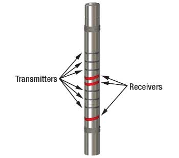
Halliburton introduced its Azimuthal Deep Resistivity (ADR) tool, a multifrequency propagation-resistivity design that employs new sensors and tilted coils.30 The ADR makes about 2,000 measurement per depth station and simultaneously acquires Rh, Rv and dip data at three frequencies: 125 kHz, 500 kHz and 2 MHz. The resistivity sensors consist of six coaxial transmitters and three receiver coils that are tilted at 45°, Fig. 4. This arrangement provides compensated phase-shift and attenuation resistivity curves with matched 8-in. (20.5-cm) vertical resolution and 14 depths of investigation, ranging from 16 in. (41 cm) to 18 ft (708 cm). The high-frequency, short-spacing resistivity measurements are used to map the near-wellbore properties. The longer-spacing and lower-frequency measurements are used to characterize the uninvaded zone. The processing software automatically corrects for shoulder-bed effect, producing a more accurate determination of formation resistivity and anisotropy. As the tool rotates, the resistivity data is acquired in 32 azimuthally oriented bins (11.25° azimuthal resolution) that are referenced to either the high side of the borehole or magnetic north. The tool, a single 25-ft (7.6-m) collar, is available in two sizes, 4¾ in. (121 mm) and 6¾ in. (171 mm), to accommodate hole sizes ranging from 5⅞ in. (149 mm) to 10⅝ in. (270 mm). The ADR tool is fully compatible with the IntelliServ wired-pipe network.
 |
|
Fig. 4. Sensor configuration of Halliburton’s Azimuthal Deep Resistivity (ADR) tool. The tool is composed of a single collar with six transmitters and three tilted receivers to acquire azimuthal compensated resistivity measurements with different depths of investigation.30
|
|
The prototype of Baker Hughes’ Azimuthal Propagation Resistivity (APR) service is currently undergoing field tests.31,32 Unlike propagation-resistivity devices, APR employs a cross-coil configuration (axial transmitter and transverse receiver) and uses a three-coil bucking system, much like traditional wireline induction tools. This design allows it to be run in both water- and oil-based mud. The APR tool operates at 400 kHz and 2 MHz and acquires 16-sector azimuthal data that is presented as borehole images. It is designed to operate in conjunction with a conventional LWD propagation-resistivity device and a deep-reading device.
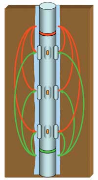
Electrode device. Halliburton’s Azimuthally Focused Resistivity (AFR) tool is also in field-test phase.33 This compact, focused-electrode device consists of two symmetrically opposed multifrequency transmitters and nine current-sensing electrodes arranged in three rows (“rings”) of three electrodes each. The 10-ft long tool, available in 4¾- and 6¾-in. (121- and 171-mm) collar sizes, operates in either resistivity or imaging mode. The transmitter-receiver arrangement in the 6¾-in. tool provides simultaneous acquisition of compensated azimuthal focused-resistivity (laterolog-type) measurements at three depths of investigation, 2.5, 7.0 and 11.0 in. (6.4, 17.8, and 27.9 cm), Fig. 5. This arrangement also allows acquisition of limited directional data in sliding (non-rotating) mode. The tool also makes an unfocused “at-bit” toroidal-resistivity measurement.
 |
|
Fig. 5. The upper (red) and lower (green) transmitters on Halliburton’s Azimuthally Focused Resistivity (AFR) tool apply small AC voltages to the drill collar. Portions of the resultant currents penetrate the formation and return to the imaging electrodes (solid lines); other field lines return to the tool body and act as guard currents.33
|
|
Time-domain ElectroMagnetic (TEM) device. Shell is conducting theoretical investigations into the use of TEM technology in an LWD device.34 Current LWD EM tools operate in the frequency domain or use DC methods. TEM, a widely used surface geophysical exploration method, involves measuring the decay of an EM field once a constant transmitter current is shut off; it has not been attempted in a downhole environment. TEM offers the possibility of greatly enhanced depths of investigation for deeper imaging ahead of the bit.
Acoustic logging. The first LWD multipole shear-wave devices operated at and above 4 kHz to avoid the effects of drilling- and mud-circulation-related noise-which occurs in the 0-3 kHz range-on the shear-slowness measurement. Unfortunately, signal dispersion in the 4 kHz range can also significantly affect the shear-velocity measurement, especially in heavy drilling mud. Although dispersion corrections were developed, they were still accompanied by a degree of uncertainty.
To minimize these dispersion effects and improve the quality of the shear-wave measurement, Baker Hughes and Halliburton have developed broadband acoustic sources that operate in the 2-3 kHz range. Baker Hughes minimizes the impact of drilling-related noise by operating its acoustic source at higher power to increase the signal-to-noise ratio.35 Halliburton’s tool uses a programmable source and a more sensitive receiver design.36
Seismic While Drilling (SWD). SWD provides 1) correlation with surface seismic through interval velocity, checkshot and Vertical Seismic Profiling (VSP) surveys, and 2) imaging ahead of the bit for predicting potential hazards (overpressuring) and optimizing casing and coring points. The advantages and disadvantages of the current methods and the historical development of SWD were reviewed in a recent SPE paper.37
Drillbit techniques (also called reverse VSP; e.g., International Logging’s Seisbit service38) use a roller-cone drillbit as a downhole seismic source in combination with surface geophones.
Hydroseis is a new service developed by Tempress Technologies and Baker Hughes Inteq, with funding from the US Department of Energy.39 The prototype uses a swept-impulse hydraulic source-i.e., a strong suction pulse at the bit- to generate a broadband seismic signal. The primary advantages of this system over current services are that 1) it is not limited to roller-cone bits, and 2) it can operate in deviated wells. Data accuracy is comparable to conventional checkshot VSP and sonic-log data.
LWD methods (VSP-while-drilling; e.g., Schlumberger’s seismicVision40) acquire seismic data during interruptions in drilling using conventional surface seismic sources and downhole acoustic or triaxial seismic receivers, positioned near the drillbit in the LWD assembly. Only the checkshot data is transmitted to the surface in real time using conventional mud-pulse telemetry; the full waveforms are stored downhole and retrieved later. This method relies on good downhole acoustic coupling between the receivers and the borehole, and on the accuracy and precision of the downhole clock used for synchronization with the surface equipment. The prototype of Halliburton’s new LWD SWD service recently completed successful field tests.41 The tool, designed for operation to 330°F (165°C) and 25,000 psi (172.4 MPa), is comprised of four geophones, four internal and four external accelerometers, four hydrophones that can be configured in any of the three principal axes, a triaxial accelerometer, and a biaxial magnetometer; the quartz clock is designed to an accuracy of ±1 ms per 200 hr.
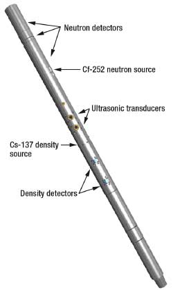
Nuclear measurement. Pathfinder’s Slim Neutron Density Standoff Caliper (SNDSC) tool is designed for use in boreholes as small as 5⅞ in. (150 mm).11,12 It is part of the HPHT Survivor suite (mentioned above) and can be run in combination with the Survivor resistivity tool as a slim “triple combo” log, although its modular design allows it to be placed anywhere in the toolstring. The tool uses a conventional cesium-137 source for the spectral bulk density and a californium-252 neutron source and three detectors to provide three thermal neutron porosities, Fig. 6.
 |
|
Fig. 6. Pathfinder’s Slim Neutron Density Standoff Caliper (SNDSC) LWD porosity tool, showing the relative positions of the neutron and density sources and receivers, and the ultrasonic transducers used for caliper and standoff measurements.11
|
|
The new californium-252 source provides a comparable neutron output to conventional Am-Be sources in a smaller volume and with substantially less radiation. The lower-energy output improves porosity sensitivity. Additional environmental benefits are a much-reduced half-life (2.65 yr vs. 433 yr), which promotes source recycling every 4-5 yr. Two ultrasonic transducers provide tool standoff measurements that are used to weight the nuclear measurements-allowing the tool to be run slick (sleeveless)-and a borehole-caliper measurement. A new “water subtraction” neutron-processing method with smaller standoff and hole-size effects has been developed for this tool.
RIGSITE EVALUATION
Besides downhole equipment, advances have also been made in the ability to gather well data from recycled drilling fluid, cuttings and other sources at the surface.
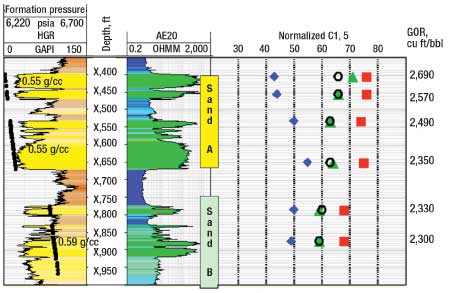
Mud gas system. Shell’s extensive field experience with Geoservices’ advanced mud gas system, Flair, shows that the surface-derived fluid-properties data obtained with this system are very close to results obtained downhole using advanced formation-tester fluid-analysis techniques, Fig. 7.42 The Geoservices system is composed of a very efficient gas extractor coupled with the company’s Flex constant-volume degasser, a sample handler, and analytical tools including a gas-phase chromatograph-mass spectrometer and the Flair detector. Data on fluid properties (e.g., composition) is used for quantitative identification of different fluid types (fluid facies) in the well before well logging.
 |
|
Fig. 7. Comparison of results from the Advanced Mud-Gas (AMG) system (green triangle) with downhole fluid analysis data (red square), on-site PVT compositional data (blue diamond) and lab-based PVT compositional data (open circle).42
|
|
The concept of fluid facies can be applied to reservoir characterization, identification of cap-rock effectiveness and fluid contacts, designing the appropriate LWD toolstring, determining the optimal number of fluid sample points, multi-well correlation, and locating bypassed pay (in the absence of logging data). Real-time information regarding variations in fluid facies can assist in geosteering high-angle and horizontal wells.
Petrophysical properties from cuttings. IFP has led efforts to determine petrophysical properties (e.g., porosity, permeability and NMR T2) directly from cuttings. A recent technical paper reviews the state of the art and describes improved methods.43 Two observations, in particular, are worth noting. The authors found that using centrifuge or porous-plate methods to remove the interstitial liquids allows accurate porosity measurements on cuttings as small as 0.5 mm when the permeability is less than 1 mD. A field test demonstrated that, using porosity, the depth-match discrepancy between cuttings and logs can be less than 1 m.
Portable NMR probe. A portable NMR surface probe has been used to measure self-diffusion in liquid-filled porous media.44 Two important petrophysical parameters-surface-to-volume ratio and formation factor-can be determined from the time dependence of the diffusion coefficient. The probe, contained in a copper and aluminum housing, is the size of a 10-in. (250 mm) cube and weighs 85 lb (38.5 kg); the portable electronic subunit (33 lb, 15 kg) uses conventional 110- or 220-V power. The frequency range of the resonant circuit is tunable between 5.2 and 9 MHz. While this range is higher than the 2-MHz devices typically used in petrophysical logging and laboratory analysis, this device, or some modification, may have application in wellsite or laboratory analysis.
WELL LOGS AND CLIMATE CHANGE
With all the current discussion of climate change, few people outside of academic research are familiar with the role that well logs play in this debate-namely, that log data serve as climate-change proxies. Short-term changes in climate (the past 1,000 years) are analyzed using borehole-temperature measurements; this research is called “borehole climatology.” Long-term trends occurring in the distant geological past (100,000 to millions of years) are analyzed using spectral analysis of the lithologic cycles recorded by logs; this research is called “climate stratigraphy.” Two recently published books provide in-depth discussions of the research conducted in these two areas over the past 30 years.45,46
Borehole climatology. The idea that subsurface temperature disturbances might serve as indicators of changes in ground surface temperature was first suggested in the 1920s, but it wasn’t until the late-1970s that studies of the connection between borehole temperatures and past climate really developed. Temperature changes (anomalies) at the earth’s surface propagate downward, as a thermal signal superimposed on the geothermal gradient, to depths that depend on the magnitude and duration of the temperature disturbance at the surface. The thermal signal is contained in borehole temperature measurements that are analyzed to reconstruct the surface temperature history (i.e., climate) over several centuries. The climate signal is attenuated with depth and time, and data resolution also decreases with time. Research borehole locations are carefully chosen to avoid or minimize natural and manmade factors that influence surface temperature.
Climate stratigraphy. Oscillations in global climate are cyclical responses to periodic orbital perturbations of the Earth known as “Milankovitch cycles.” The duration of these cycles ranges from 21,000 to 413,000 years. Orbitally-forced changes (cycles) in solar energy produce changes in temperature, humidity and rainfall, which in turn influence lithological properties (e.g., clay mineralogy, clay content and grain size) and changes in the lithofacies deposited in a basin.
Cyclostratigraphy is a relatively new discipline that developed in the late 1980s, in part out of findings gained with the Ocean Drilling Program. It is based on the recognition that climate change follows recognizable and predictable patterns that, in turn, allow prediction of lithofacies. The vertical lithofacies patterns present in a borehole or outcrop retain a record of these orbital periodicities, and facies-sensitive well logs (e.g., acoustic, gamma-ray and resistivity logs) can be related to patterns of climate history and depositional cycles. Well logs are comprised of continuous and regularly sampled data and therefore represent a time-series record that can be studied using spectral-analysis mathematical methods.47 The climate-sensitive information is contained in the spectral properties (wavelength, amplitude and phase).
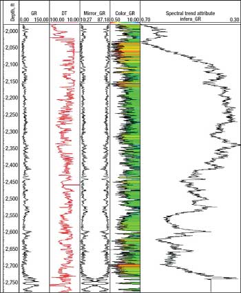
A commercial software tool has been developed specifically to perform these analyses. Cyclolog is a Windows-based program created by Enres International to conduct both conventional and spectral log analysis using LAS- or ASCII-formatted data, Fig. 8.48
 |
|
Fig. 8. Cyclolog display showing mathematical transformations of gamma-ray and acoustic log data to reveal spectral trends in the data.47
|
|
GENERAL
On a historical note, SAID, SPWLA’s Paris Chapter, held a special symposium in Pechelbronn, France, marking the 80th anniversary of the first electric log. The technical presentations included historical reviews as well as discussions of current developments and future opportunities in energy exploration and exploitation. SPWLA published summaries and extended abstracts of these presentations in the December 2007 issue of Petrophysics. 
LITERATURE CITED
1 Fitzgerald, P. and B. K. Pedersen, “A technique for improving the accuracy of wireline depth measurements,” SPE 110318 presented at the SPE Annual Technical Conference and Exhibition, Anaheim, Calif., Nov. 11-14, 2007.
2 Bordakov, G. A. et al., ”Improving LWD image and formation evaluation by utilizing dynamically corrected drilling-derived LWD depth and continuous inclination and azimuth measurements,” SPE 109972 presented at the SPE ATCE, 2007.
3 Wittrisch, C., “Semi rigid logging cable a new concept to make logging possible in highly deviated and horizontal wells,” presented at the Offshore Mediterranean Conference and Exhibition, Ravenna, Italy, March 16-18, 2005.
4 Rabinovich, M. et al., “Multi-component induction logging: 10 years after,” paper CC presented at the SPWLA 48th Annual Logging Symposium, Austin, Texas, June 3-6, 2007.
5 Zhang, Z. et al., “Triaxial induction logging: An operator’s perspective,” paper Y presented at the SPWLA 48th Annual Logging Symposium, 2007.
6 Geldmacher, I. M. and J. Jonkers, “A through-casing-resistivity field trial in Alberta, Canada,” paper Z presented at the SPWLA 48th Annual Logging Symposium, 2007.
7 Nichols, D., “Topic paper #21: Exploration technology,” Appendix 7: Subsurface measurements, in National Petroleum Council, Hard Truths: Facing the Hard Truths About Energy, 2007, http://downloadcenter.connectlive.com/events/npc071807/pdf-downloads/Study_Topic_Papers/21-TTG-ExplorationTech.pdf.
8 Ferguson, C. D. et al., “Commercial radioactive sources: Surveying the security risks,” Center for Nonproliferation Studies, Monterey Institute of International Studies, Occasional Paper No. 11, 2003, cns.miis.edu/pubs/opapers/op11/op11.pdf.
9 “Project: Radiation source use and replacement,” The National Academies website, http://www8.nationalacademies.org/cp/projectview.aspx?key=48677.
10 Peeples, C. R., “Alternatives to the Americium-Beryllium neutron source for the compensated neutron porosity log,” MS thesis, North Carolina State University, 2007, http://www.lib.ncsu.edu/theses/available/etd-11082007-174605/unrestricted/etd.pdf.
11 Valant-Spaight, B. et al., ‘Field examples with a slim LWD density/neutron instrument containing a californium-252 neutron source and three neutron detectors,” paper CCC presented at the SPWLA 47th Annual Logging Symposium, Veracruz, Mexico, June 4-7, 2006.
12 Sarian, S. and A. Gibson, “Wireline evaluation technology in HPHT wells,” SPE 97571 presented at the SPE High Pressure/High Temperature Sour Well Design Applied Technology Workshop, The Woodlands, Texas, May 17-19, 2005.
13 Rennie, A. and P. Boonen, “An LWD suite for formation evaluation in HP/HT environments,” SPE 109940 presented at the SPE ATCE, 2007.
14 “Weatherford: LWD,” Weatherford International website, http://weatherford.com/weatherford/groups/public/documents/drilling/ds_lwd.hcsp.
15 Mendoza, A. et al. “Why the LWD and wireline gamma ray measurements may read different in the same well,” SPE 101718 presented at the International Oil Conference and Exhibition in Mexico, Veracruz, Mexico, June 27-30, 2006.
16 Dong, C. et al., “New downhole fluid analyzer tool for improved reservoir characterization,” SPE 108566 presented at Offshore Europe Oil and Gas Conference and Exhibition, Aberdeen, Sept. 4-7, 2007.
17 O’Keefe, M. et al., “In-situ density and viscosity measured by wireline formation testers,” SPE 110364 presented at the SPE Asia Pacific Oil and Gas Conference and Exhibition, Jakarta, Oct. 30-Nov. 1, 2007.
18 Johns, J. E. et al., “Applied ultrasonic technology in wellbore leak detection and case histories in Alaska North Slope wells,” SPE 102815 presented at the SPE Russian Oil and Gas Technical Conference and Exhibition, Moscow, Oct. 3-6, 2006.
19 Johns, J. E. et al., “Locating and repairing casing leaks with tubing in place: Ultrasonic logging and pressure-activated sealant methods,” SPE 108195 presented at Offshore Europe, 2007.
20 Vu-Hoang, D. et al., “A novel approach to production logging in multiphase horizontal wells,” SPE 89848 presented at the SPE Annual Technical Conference and Exhibition, Houston, Sept. 26-29, 2004.
21 Mukerji, P. et al., “The role of enhanced production logging measurements in challenging openhole horizontal completions,” SPE 102198 presented at the SPE Annual Technical Conference and Exhibition, San Antonio, Texas, Sept. 24-27, 2006.
22 Weisbeck, D. et al., “Case history of first use of extended-range EM MWD in offshore, underbalanced drilling,” IADC/SPE 74461 presented at the IADC/SPE Drilling Conference, Dallas, Feb. 26-28, 2002.
23 Wind, J. et al., “Successful integration of electromagnetic MWD-LWD technology extends UBD operation envelope into severely depleted fields,” SPE/IADC 92617 presented at the SPE/IADC Drilling Conference, Amsterdam, Feb. 23-25, 2005.
24 Muqeem, M.A. et al., “The introduction of electromagnetic LWD technology in Saudi Arabia: A case history and future application of underbalanced campaigns,” SPE/IADC 105471 presented at the SPE/IADC Drilling Conference, Amsterdam, Feb. 20-22, 2007.
25 Gao, L. et al., “Acoustic telemetry can deliver more real-time downhole data in underbalanced drilling operations,” IADC/SPE 98948 presented at the IADC/SPE Drilling Conference, Miami, Fla., Feb. 21-23, 2006.
26 Neff, J. M. and P. L. Camwell, “Field-test results of an acoustic MWD system,” SPE/IADC 105021 presented at the SPE/IADC Drilling Conference, 2007.
27 Wolter, H. et al., “The first offshore use of an ultrahigh-speed drillstring telemetry network involving a full LWD logging suite and rotary-steerable drilling system,” SPE 110939 presented at the SPE ATCE, 2007.
28 Schiavon, R. et al., “A new ultra high data rate telemetry systems (UDRT) for geosteering applications,” presented at the Offshore Mediterranean Conference and Exhibition, Ravenna, Italy, March 28-30, 2007.
29 Ekseth, R. et al., “High-integrity wellbore survey: Methods for eliminating gross errors,” SPE/IADC 105558 presented at the SPE/IADC Drilling Conference, 2007.
30 Bittar, M. et al., “A new azimuthal deep-reading resistivity tool for geosteering and advanced formation evaluation,” SPE 109971 presented at the SPE ATCE, 2007.
31 Bell, C. et al., “Navigating and imaging in complex geology with azimuthal propagation resistivity while drilling,” SPE 102637 presented at the SPE ATCE, 2006.
32 Wang, T. et al., “Real-time formation imaging, dip, and azimuth while drilling from compensated deep directional resistivity,” paper NNN presented at the SPWLA 48th Annual Logging Symposium, 2007.
33 Prammer, M. G. et al., “Field testing of an advanced LWD imaging/resistivity tool,” paper AA presented at the SPWLA 48th Annual Logging Symposium, 2007.
34 Banning, E.J. et al., “Imaging of a subsurface conductivity distribution using a time-domain electromagnetic borehole conveyed logging tools,” presented at the 77th SEG Annual Meeting, San Antonio, Texas, Sept. 23-28, 2007.
35 Tang, X.M. et al., “Development of a low-frequency quadrupole shear-wave technology to improve quality of LWD shear velocity measurement,” SPE 102335 presented at the SPE ATCE, 2006.
36 Market, J., “New broad frequency LWD multipole tool provides high quality compressional and shear data in a wide variety of formations,” paper A presented at the SPWMLA 48th Annual Logging Symposium, 2007.
37 Anchliya, A., “A review of seismic-while-drilling (SWD) techniques; a journey from 1986-2005,” SPE 100352 presented at the SPE Europec/EAGE Annual Conference and Exhibition, Vienna, Austria, June 12-15, 2006.
38 International Logging, Inc., Seisbit brochure, 2004, http://www.inter-log.com/images/downloads/inlidownloads/brochures/03%20Seisbit%20Flier%20june%201st%202004.pdf.
39 Kolle, J. J. and K. Theimer, “Seismic-while-drilling using a swept impulse source,” SPE/IADC-92114 presented at the SPE/IADC Drilling Conference, 2005.
40 Underhill, W. et al., “Demonstrations of real-time borehole seismic from and LWD tool,” SPE 71365 presented at the SPE Annual Technical Meeting and Exhibition, New Orleans, Sept. 30-Oct. 3, 2001.
41 Dethloff, M. H. and S. A. Petersen, “Seismic-while-drilling operation and applications,” SPE 109893 presented at the SPE ATCE, 2007.
42 McKinney, D. et al., “Advanced mud gas logging in combination with wireline formation testing and geochemical fingerprinting for an improved understanding of reservoir architecture,” SPE 109861 presented at the SPE ATCE, 2007.
43 Lenormand, R. and O. Fonta, “Advances in measuring porosity and permeability from drill cuttings,” SPE 111286 presented at the SPE/EAGE Reservoir Characterization and Simulation Conference, Abu Dhabi, Oct. 28-31, 2007.
44 Marko, A. et al., “Application of a portable nuclear magnetic resonance surface probe to porous media,” Journal of Magnetic Resonance, 185, No. 1, 2007, pp. 19-27.
45 Bodri, L., and V. Cermak, Borehole Climatology: A New Method on How to Reconstruct Climate, Elsevier, 2007.
46 Nio, S. D., Climate Stratigraphy: Principles and Applications in Subsurface Correlation, EAGE, 2006.
47 Weedon, G. P., Time-Series Analysis and Cyclostratigraphy, Cambridge University Press, 2003.
48 “Cyclolog,” Enres International website, http://www.enresinternational.com/Cyclolog/cyclolog.php.
|
THE AUTHOR
|
|
|
Stephen Prensky is a consultant to logging service companies, with 33 years’ working experience in petroleum geology and petrophysics. He previously worked for Texaco, the US Geological Survey and the Minerals Management Service. He has served as the SPWLA vice president of technology and as editor of SPWLA’s Petrophysics. He now serves on the SPWLA Technology Committee. In addition to SPWLA, he is a member of AAPG and SPE.
|
|
|


