Expandable technology matures
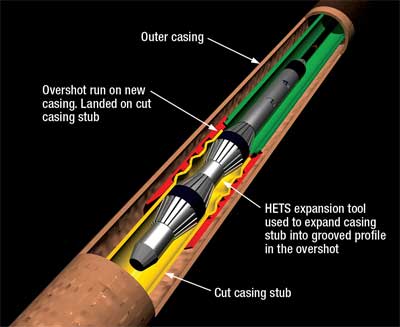
After many years of tool and application development, niches continue to be filled as operators face multiple well challenges.Victor Schmidt, Drilling Engineering Editor After more than 14 years of development, the market for expandable tubulars has matured, gauging by the modest number of new product offerings coming to market. Most of the niches have been filled and the industry now has a wide variety of expandable products at its disposal to help overcome the drilling, casing and production problems that it routinely encounters. Baker opened the market in 1994 with the ZXP* liner packer system, followed by Weatherford in 1998 with its ESS* technology for sand control. Enventure entered in 1999 with the SET* system. Others followed quickly including READ Well Services, which began its HETS* development in 2000, and Halliburton with its PoroFlex* system in 2001 and its VersaFlex* system in 2002. TIW introduced the 2T-XPatch* in 2003. These systems use pipe conveyance to place and expand the tools, but wireline versions are coming to market soon. Below are the latest developments in this most flexible, problem-solving tool class. READ Creating a gas-tight seal. The Hydraulically Expandable Tubular System (HETS)* solid expandable well design and construction tools continue to develop with several successful deployments over the last year. This includes expansion of conventional casing for external casing patches, internal expansion patches, liner hangers for well construction and remedial well engineering, and qualification testing of zonal isolation packers. One of the new applications was the development of an External Patch (EP), Fig. 1. At the top of an Oseberg East Field well in the North Sea, the 9 5/8-in. casing lost integrity and required a gas seal for future gas lift. HETS was deployed after StatoilHydro (operator) selected the EP, based on its metal-to-metal gas seal, ID preservation and a 300,000-lb load capability at up to 125°C. This approach was preferred to reducing well diameter with a scab liner.
The 9 5/8-in. casing was cut below the corrosion and leak site, but above the 13 5/8-in. shoe. Pipe was recovered by tying back the 9 5/8-in. casing to the 13 3/8-in. by running a conventional liner hanger and casing packer above a short string of new 95/8-in. casing, which was connected to the old 9 5/8-in. casing with the EP. This 9 5/8-in. × 13 3/8-in. string provided one of two integrity barriers around a gas-lift completion. The company is in discussions with a major Norwegian operator to deploy the EP upside down and to run it as part of the completion string. This application will remove the need for a PBR assembly in a long-reach multilateral well. The patch’s gas seal ensures casing integrity and allows gas-lift valves to be installed below the EP connection. The number of applications continues to develop and expand as this technology matures, and several developments are underway. A major Norwegian-sector North Sea operator recently approached the company for an expandable Casing Packer (CP) to prevent gas migration up the annulus between a 9 7/8-in. casing and an 11 3/4-in. liner. A conventional packer was available between the 9 7/8-in. and 13 3/8-in. casing higher in the well, but could not be used since the 13 3/8-in. connections were not gas tight. A conventional packer for 9 7/8-in. × 11¾-in. casing did not exist, so the company was asked to develop an expandable tool. The CP will be run as part of the 9 7/8-in. casing string-essentially an 11-ft pup joint-and have the same drift diameter as the 8½-in. casing and a maximum OD of 10.1 in. to reduce ECD problems when running through the 11¾-in. liner. With the 9 7/8-in. casing landed, the shoe will be cemented and the expansion tool will be run on drill pipe. Hydraulic pressure will set the packer using a downhole hydraulics intensifier. The CP is in testing with a specification target of 3,000-psi external gas pressure to ISO14310:V0 rating and +/-700,000-lb load rating. Field-ready CPs will be available late in 2008. Presently, the expansion system is only available for 7-in. and larger tubulars. A JIP was started at the end of 2006 with five industry sponsors, to develop a SlimHETS system for 4½-in. and 5½-in. tubulars. This prototype is still in development, but will be ready for field testing in late 2008. The project focuses on wireline conveyence and includes development of a 3 ½-in. OD Power Pack and an internal patch. Once these are ready, other tools will be added for these tubulars, as well as a hydraulic system for drill pipe or coiled tubing conveyence. WEATHERFORD Frac-packing multi-zone slimholes. Weatherford is developing a method of frac-packing multi-zone slimholes and sidetracks, using solid and slotted expandable casing to enhance production rates. This technique replaces the production liner, cementing and perforating phases in a normal completion. The increased completion ID and flow areas in the expandable completion allow a significant increase in the frac-pack sand-screen size and associated production tubulars. The expanded completion liner offers more than a 10-fold increase in inflow area over a conventional perforated liner, according to the company. These combined factors allow improved production rates from 6-in., openhole-sidetracked, sand control wells requiring frac-packing. By using an expandable slotted completion liner in conjunction with a newly developed solid expandable openhole packer system, the operator can selectively expand production (or injection) zones and, with an appropriate frac-pack screen design, effectively control flow from individual zones, Fig. 2. Using selectively-expandable isolation devices allows the operator to decide on placement after the well evaluation data has been analyzed. This flexibility optimizes the completion’s effectiveness.
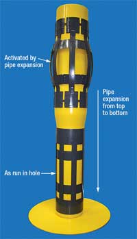
The new system allows an operator to perform an open-hole frac-pack inside a 6-in. sidetracked hole, obtain higher sustained production rates and improve project economics over conventional techniques. In some cases, the system will allow additional reserves recovery in difficult sand-control environments and can help revitalize maturing fields. BAKER OIL TOOLS Close-tolerance expandable centralizer. Baker has developed the first close-tolerance expandable centralizer. The patent-pending device was jointly developed by Antelope Oil Tool and Baker Oil Tools to meet the industry’s need for proper centralization of expandable tubulars. The device was developed over 12 months, tested first in the lab and then in downhole field trials with good success. The slip-on design does not require stop collars or set screws, uses heat-treated bows from 4130 steel and runs into the hole in a collapsed mode, allowing passage through tight restrictions. The centralizer opens during pipe expansion from top to bottom, Fig. 3.
According to the company, the device can be installed anywhere on the pipe, is pipe safe and doesn’t score or mark pipe in any way. Since the centralizer is flush to the pipe during run-in, there is no starting or running force going in hole. During pipe expansion, there is sufficient restoring force to open the centralizer inside an underreamed open hole. The tool remains tightly secured to the pipe after expansion. During development, there were two main challenges: securing the centralizer onto the pipe and expanding the end collar. Attempts to fix the end collars with epoxy and friction stops failed; however, friction worked. The centralizer is locked to the pipe with 20,000 lb of holding force, provided by the bows in their collapsed mode. After expansion, the end collar design provides residual tension to hold the centralizers in place. Finite element analysis showed that solid end collars would not stand the expansion ratio without rupture, but that a variable geometry design would work. Several profiles were tried and lab tested, leading to the present design. The expandable centralizer is presently available for 8-in. OD expandable pipe with an 8½-in. restriction pass-through. Pipe expansion will open the pipe to 9.287-in. OD and open the centralizer into a 10¼-in. open hole. The tool can provide centralization in open holes up to 12¼ in. and is scalable to other tubular sizes. ENVENTURE With a decade of practical application, operators are building expandable casing into well plans through well-slimming designs and planned applications, driven by NPT reductions and benefits from preserved hole size. According to the IHS database, in the 1990s, there were 246 wells in water deeper than 4,000 ft; from 2000 through 2007, there were 757 wells added to the list. Prior to 2000, only 27 wells were drilled to a TD deeper than 20,000 ft in water depths of over 4,000 ft. Of those, only seven were drilled deeper than 25,000 ft. Since then, the deepwater list has grown by more than 563 wells deeper than 20,000 ft, including 122 wells below 25,000 ft. The Gulf of Mexico is a prime example of expandable growth in deepwater applications. Expandables have played an important role in drilling more than 116 deepwater wells. In the GOM, solid expandable tubulars have been installed in 15 wells below 20,000 ft with setting depths ranging from 22,072 to 28,742 ft. To date, the operating envelope for expandable technology includes installations in a 28,750-ft-MD deepwater well, with lengths up to 6,867 ft, in 400°F temperatures, at 100° inclinations and using 20-ppg mud. Industry acceptance of solid expandable technology has led to longer liners. Single liner runs of 4,000 to 6,000 ft are not uncommon today, where a few years ago the norm was 500-2,000 ft. Engineers are increasingly planning with sizes larger than 9 5/8 in., taking advantage of the flexibility larger sizes offer in designing the upper wellbore architecture, Fig. 4. An operator study of expandables estimated that timely, appropriate installation would save an average $2 million per rig year. The study’s 164 GOM wells represented $2.84 billion of drilling expenditure and 29.3 rig years. More than 6,900 hr of NPT were extracted and analyzed.1
The study showed that the probability of a wellbore-related NPT event lasting longer than six days increased with depth-about 40% in holes 8½ in. or less. The majority occurred below intermediate casing. The study indicated a two-day trigger for installation of an openhole liner after an NPT event lasting longer than six hours. Pre-positioning liner equipment ensures an optimal response. Much of present operator planning is focused on well-slimming designs using expandables in the upper hole. Risk is reduced because working higher in the hole provides a more stable wellbore environment. Success is enhanced by greater casing clearances and lower expansion parameters of larger-diameter expandables. Working in the upper hole reduces trip time and limits the demand for special casing sizes. A slimmer wellbore also results in faster penetration rates using smaller bits and less fluid. With a slimmer pipe design, mechanical loads and stress are reduced. This can permit drilling with an earlier-generation rig, making development, completions and intervention more cost-effective. For instance, instead of an 18 3/4-in. subsea BOP stack and 21-in. marine riser, a design using a 13 5/8-in. BOP and 16-in. riser at surface will retain an adequate hole size at TD. Designs can be constructed using second- and third-generation semisubmersibles using a smaller riser. By designing wells with expandables as an integral component, operators are exploring a new world of well construction options. Wellbore slimming is improving capabilities and economics, and creating viable prospects from distant reserves. Operators are also anticipating problems. With equipment ready, they can respond to wellbore circumstances before problems become major NPT sources. From exploratory drilling to sidetrack developments to the extremes of extended reach offered by monodiameter technology, planned-expandables use is opening new horizons for deepwater exploration and development. TIW Large-OD ELH systems. To date, TIW has deployed 85 XPak Expandable Liner Hanger (ELH)* systems in operators’ wells. The initial focus during development was on 75/8-in. × 95/8-in. and 5½-in. × 7 5/8-in. sizes. Deepwater and ERD operators see potential for the expandable hanger in their operations. Therefore, recent focus has been on developing large-OD ELH systems. In 2008, the company deployed two 13 3/8-in. × 16-in. systems. A 16-in. × 20-in. system has been built and is awaiting deployment in the North Sea. The company has also completed testing of an 18-in. × 22-in. system. The operator required a system that would suspend a liner load of 1.2 million lb. During testing, the hanger setting required 1.3 million lb of force to complete the expansion. After setting the hanger, a pull test was successful to 1.6 million lb. Although the testing was successful, the project was put on hold and the company has yet to deploy an 18-in. × 22-in. system. Development of the large-OD ELH has presented several challenges including wide ID variances, ovality and weld seams in electric-resistance-welded pipe. Initial testing of 13-chrome hanger systems did not go well. Galling across the ID of the expandable section, as the expander was pushed into it, resulted in a lock-up effect that exceeded the force capability of the hydraulic setting tool and stalled the expansion. Researchers tried several materials without success and then began investigating coatings. Today, the casing uses a proprietary coating that eliminates galling. The company has successfully expanded a 13-chrome hanger system in a test well. Click here for a complete list of World Oil’s annual expandable technology reports. LITERATURE CITED 1 Mason, D., Cales, G., Holland, M. and J. Jopling, “Using an engineering analysis process to identify pragmatic applications for solid expandable tubular technology,” OTC 17438-PP presented at the Offshore Technology Conference, Houston, Texas, May 2-5, 2005. *Indicates trademarked names, which are the property of the respective company in the section where the name appears.
|

- Coiled tubing drilling’s role in the energy transition (March 2024)
- What's new in production (February 2024)
- Using data to create new completion efficiencies (February 2024)
- Digital tool kit enhances real-time decision-making to improve drilling efficiency and performance (February 2024)
- E&P outside the U.S. maintains a disciplined pace (February 2024)
- U.S. operators reduce activity as crude prices plunge (February 2024)
- Applying ultra-deep LWD resistivity technology successfully in a SAGD operation (May 2019)
- Adoption of wireless intelligent completions advances (May 2019)
- Majors double down as takeaway crunch eases (April 2019)
- What’s new in well logging and formation evaluation (April 2019)
- Qualification of a 20,000-psi subsea BOP: A collaborative approach (February 2019)
- ConocoPhillips’ Greg Leveille sees rapid trajectory of technical advancement continuing (February 2019)

