Using micro-structural and metallurgical criteria to develop alloys leads to a compromise between tool joint wear and casing wear resistance.
John G. Mobley and Roger A. Daemen, Arnco Technology Trust, Ltd.
Iron-based alloys are used to overlay drill pipe tool joints and other drilling equipment by welding processes. This article describes an alloy design process that, in addition to the traditional design criteria, integrates micro-structural characterization as essential to optimize the required properties. With respect to tool joint hardbanding, two different situations need to be distinguished: openhole drilling and cased-hole drilling.
In openhole drilling conditions, wear affects the drillstring components. The wear mode involved is essentially grinding and gouging abrasion. In cased-hole conditions, although tool joint wear is an important factor, emphasis shifts to the question of how to minimize wear caused by the tool joint on the inside of the casing. The wear modes involved in cased-hole drilling are more complex, as they combine abrasion with metal-to-metal wear mechanisms.
WEAR RESISTANCE ASSESSMENT CRITERIA
To classify alloys in terms of their relative wear resistance, five main criteria are commonly used:
- Hardness
- Relative weight loss
- Results of reduced scale simulation
- Carbon content
- Micro-structural states and features.
Since high hardness is traditionally associated with high wear resistance, the hardness criterion is by far most commonly referenced when classifying alloys. Hardness is measured simply and quickly using relatively unsophisticated fixed or portable equipment.
Conventional wear-test data is typically generated by alloy designers and by welding consumable developers. Such data, except for certain groups of alloys, do not correlate with hardness data because micro-structural differences may affect alloys with the same level of hardness.
Reduced-scale simulation tests are specific to each type of industry. The Maurer or Mohr tests are used mostly in determining alloy properties in this article.
Carbon content and micro-structural features are intimately related. A common rule for iron-based alloy systems that has been confirmed by many observations is: the higher the carbon content, the higher the wear resistance. Micro-structures are also significantly affected by the presence of other alloying elements. These elements fall into three categories: austenite phase stabilizers (C-Mn-Ni), ferrite phase stabilizers (Cr-Si-Mo-Al) and carbide-forming elements (Cr-Nb-Ti-W-V-Mo).
To account for the extreme diversity of micro-structures as a function of composition, referring to “structural” or “constitutional” diagrams is useful. Figure 1 displays a diagram that specifically has been developed to account for micro-structures appearing in iron-based hardfacing alloys. Notable about Fig. 1:
- Carbon content is displayed in ordinates on a logarithmic scale.
- Total alloying element content is displayed in abscises on a linear scale.
- No distinction is made between elements of different natures, and interpretation of the diagram still requires some degree of metallurgical judgment.
- The E-E’ line in the upper part of the diagram defines the boundary between hyper-eutectic alloys with representative points below this line. This E-E’ line is about the same as the U1-U4-el given in Fig. 2 for the ternary Fe-Cr-C diagram.
- The lines that delineate the structural areas in the rest of the diagram have been drawn as guide lines based on the plotting of about 400 different hardfacing alloys belonging to about 12 different groups. Their location is affected by a certain degree of uncertainty.
- In moving from left to right within each structural domain, there is a gradual change from one type of dominant structure (at the left) to another form of dominant structure (to the right), with a range of mixed structures appearing in the transition.
 |
|
Fig. 1. Structural diagram illustrating ferrous-based hardfacing alloys.
|
|
 |
|
Fig. 2. Ternary Fe-Cr-C equilibrium diagram.
|
|
WEAR RESISTANCE OF OPENHOLE ALLOYS
Openhole alloys can be split into two groups: tungsten carbides and chromium carbides that contain other strong carbide formers.
W-carbides. As previously mentioned, the dominant wear mode is grinding or gouging abrasion. Abrasive wear resistance is considerably enhanced by the presence of carbides in the micro-structure of the alloys. The tungsten carbides (WC or WC-W2C), with a hardness of about 2,500 HV, are the hardest carbides, and were adopted very early as prime candidates to produce highly abrasion-resistant alloys.
W-carbide hardbandings, when properly applied using appropriate carbide particle mesh sizes and deposition methods, are unsurpassed in withstanding highly abrasive wear. They are, however, affected by a number of drawbacks that are in direct relation to their micro-structural features. WC deposits cannot be considered true alloys. The formation of the W-carbides is not the result of a precipitation process from a liquid phase. They are added as separate particles to the weld pool, so that, ideally, their dilution in the weld pool will be reduced to a minimum. From a micro-structural point of view, the result is a mixture of solid WC particles in a matrix of martensitic and secondary carbides, with a considerable disparity in hardness between the WC particles (about 2,500 HV) and the matrixes (60 HRC on average).
W-carbides are very dense materials and have a very strong tendency to segregate to the bottom of the weld pools, which creates a gradient of concentrations from top to bottom of the overlays, and results in heterogeneous properties.
Other types of carbides. A number of elements such as chromium, vanadium, molybdenum, niobium and titanium are known as strong carbide formers because they have a high affinity for carbon. Among these elements, chromium is of prime importance. Figure 2 displays the projection of the liquidus surface of the ternary Fe-Cr-C alloy system. The line U1-U4 clearly defines the existence of eutectic transformations in the group of alloys of interest for the development of wear resistant hardfacing alloys.
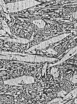
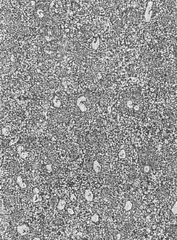
For alloys that have a hyper-eutectic composition, the first phase separating from the liquid phase is the Cr-carbide, which has a stoichiometric composition of Cr7C3. This type of carbide is characterized by a prismatic-hexagonal type of morphology, and exhibits a hardness of about 1,700 HV, which is lower than W-carbides, but significantly harder than quartz (SiO2, hardness of about 900 HV), and slightly higher than corundum (Al2O3, hardness of about 1,550 HV). Figure 3 displays an example of these primary carbides. Figure 4 displays an example of a near-eutectic structure in which Cr-carbides appear in the form of eutectic or hypo-eutectic Cr3C composition. The hardness of these latter types of carbides is typically around 60 HRC. Both of these Cr-carbides are precipitated from the liquid phase, and are therefore uniformly distributed in the structure.
 |
|
Fig. 3. Alloy A in a hyper-eutectic, undiluted state.
|
|
 |
|
Fig. 4. Alloy A in a near-eutectic, diluted state.
|
|
As a rule, the higher the concentration of carbides, particularly primary carbides, the higher the abrasion resistance. However, an opposite rule has been observed that states the higher the carbide concentration, the higher the brittleness of the alloy, which thus creates a higher risk of spalling under service conditions. All alloys in the high-chrome irons group, whether in hyper- or hypo-eutectic structural state, are prone to cracking. Hypo-eutectic structures are, however, less brittle and therefore less prone to spalling.
Strong carbide-forming elements such as niobium, titanium, vanadium and molybdenum are often added to the basic Fe-Cr-C systems of alloy to improve wear resistance through the precipitation of secondary types of carbides, which are imbedded in the eutectic matrix.
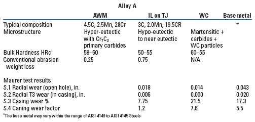
Alloy A has been developed along the above outlined principles. When considered in the undiluted condition, Alloy A’s composition is typically the following: 4.25% carbon, 2.5% manganese and 19.5% chromium. Alloy A’s representative point in Fig. 1 is “S,” and is clearly located in the hyper-eutectic structural area of the diagram.
When considered in single-layer deposit condition, which is defined by a dilution level of about 30% with the base metal, Alloy A’s composition now is about: 3% carbon, 2% manganese and 19.5% chromium. Alloy A’s representative point in Fig. 1 has now shifted to position “S1,” in a near hypo-eutectic structural state. The undiluted weld metal composition of Alloy A has been exactly balanced to ensure this type of structural transition. In a single-layer deposition, under controlled procedural parameters, Alloy A offers an optimal compromise between high abrasion resistance and minimum brittleness. Table 1 summarizes the main properties of Alloy A in terms of structure, hardness, conventional abrasion resistance and properties derived from simulation tests.
| TABLE 1. Comparitive data of base metal, tungsten carbides (WC) and Alloy A |
 |
|
CASING WEAR ALLOYS
Micro-structural criteria must be examined to create alloys that combine acceptable tool joint life and minimization of casing wear.
General considerations. The problem of designing alloys to meet the requirements of deep well-drilling conditions involves compromising between minimizing required abrasion resistance to ensure an acceptable tool joint life and minimizing the wear induced in the casing. The goal in designing alloys is to develop those whose representative points, based on Maurer or Mohr simulation tests, would ideally be located in the left-lower part of Fig. 5.
 |
|
Fig. 5. Casing wear vs. openhole tool joint wear.
|
|
Wear mechanisms and wear parameters that govern casing wear and casing wear rate are difficult to define in precise and quantifiable terms. Metal-to-metal wear under high specific pressures can be considered as the dominant mechanism. In this perspective, minimization of casing wear can be best achieved by using a tool joint hardbanding material whose interaction with the casing material leads to a state of minimum friction forces or to a state of minimum dissipated energy.
The technical literature, with the exception of a few very specific cases, is not particularly rich in useable data with respect to friction coefficients among the types of material that come into consideration for hardbanding applications. Therefore, we have elected to base our approach on micro-structural data rather than on mechanical data. These micro-structural criteria can be summarized as follows:
- Avoid alloys with hyper-eutectic compositions in which hard primary phases (carbides or borides) are precipitated
- Avoid alloys with highly carbureted eutectic phases
- Look for alloys with a dual-phased structure at minimum
- Attempt to balance the alloy compositions to achieve comparable levels of micro-hardness in all main phases present
- Give preference to fine-grained structures
- Use fine-grained and uniformly distributed particles of secondary precipitations of carbides, borides and intermetallics.
Alternatives have been explored, and two corresponding alloys have been developed: Alloy B, which has an austenitic matrix, and Alloy C, which has a ferritic matrix. The properties of these alloys have been evaluated by conventional testing methods, as well as the Maurer or Mohr simulator equipment.
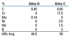
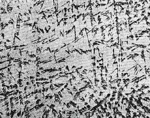
Characteristics of Alloys B and C. Table 2 displays the undiluted weld metal compositions and corresponding hardness of Alloys B and C. Although the hardness is similar, the micro-structures are very different. Alloy B, based on high carbon, is austenitic and martensitic, while Alloy C, based on boron as the hardening element, includes ferritic, eutectic and secondary intermetallics phases.
| TABLE 2. Undiluted weld metal compositions and hardness of Alloys B and C |
 |
|
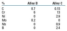
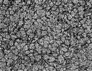
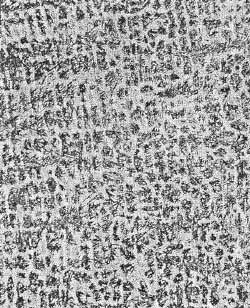
Table 3 displays the values of the diluted single-layer Alloys B and C on AISI 4145HT steel overlays with chemical compositions and hardness. The difference between the micro-structures of undiluted Alloy B and diluted Alloy B are illustrated in Figs. 6 and 7, respectively. The representative points of undiluted Alloy B and single-layer diluted Alloy B in Fig. 1 are identified as “P” and “P1,” respectively. Figure 8 shows the micro-structure of Alloy C in undiluted condition. Interestingly, the micro-structure of Alloy C in diluted condition is the same as in the undiluted condition. Since the boron-to-carbon equivalent factor is not known with sufficient precision, it is not possible to assign a representative point for Alloy C in Fig. 1.
| TABLE 3. Diluted single-layer compositions and hardness of Alloys B and C |
 |
|
 |
|
Fig. 6. Alloy B in an undiluted state.
|
|
 |
|
Fig. 7. Alloy B in a diluted state.
|
|
 |
|
Fig. 8. Alloy C in an undiluted state.
|
|
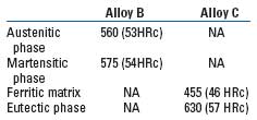
Micro-hardness data was collected from the HV10 readings, which were taken on average and are summarized in Table 4. The micro-hardness match of austenitic and martensitic phases is almost perfect for Alloy B, and is very good between the ferritic and eutectic phases in the case of Alloy C.
| TABLE 4. Micro-hardness data of Alloys B and C |
 |
|
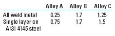
Standard ASTM Dry Sand Abrasion tests have been carried out on the alloys to determine the relative abrasion wear resistance of the alloys, and to evaluate their aptitude to ensure the minimum required openhole tool joint wear resistance. Table 5 displays the results of the sand abrasion tests, with Alloy A included for reference. The results are appropriate when considering the different types of micro-structure involved. The weight losses measured under the same conditions for a 4145 steel are 2.75 g on average, which means that the behavior of both Alloy B and Alloy C is very favorable, particularly in view of their remarkable behavior with respect to minimization of induced casing wear.
| TABLE 5. Dry-sand abrasion test data reflecting weight loss, g |
 |
|
Determining the cracking sensitivity of the overlays is important in characterizing alloys. In the appropriate conditions with respect to preheat and interpass temperature ranges, as well as to cooling rates, both described alloys can be deposited crack-free. Alloy B has an advantage over Alloy C because of its less-complex metallurgical composition and behavior, which does not involve secondary precipitation phenomena in situations where two-layer overlays are required or when re-hardbanding is envisaged. Spalling under service conditions is therefore not a concern.
CONCLUSION
Historically, tungsten hardbanding composites have been used for the purpose of protecting tool joints subjected to intensive abrasive wear in openhole drilling conditions. Under such circumstances, their behavior has remained virtually unsurpassed. In cased-hole drilling, protection of the casing takes precedence over protection of tool joints.
An intermediate step toward the development of alloys offering a better compromise between tool joint wear and induced casing wear has been achieved by developing alloys belonging to the high-chrome iron family, such as Alloy A. The properties of these alloys are in direct relation to their metallurgical and micro-structural features, which include the formation of hard carbide phases from a liquid phase and the existence of eutectic transformations in these alloy systems.
Further progress toward an optimization of alloy properties has been successfully achieved by basing alloy design on metallurgical and micro-structural criteria rather than the traditional mechanical criteria, as illustrated by the properties achieved with the development of Alloy B and Alloy C.
Conducting systematic metallographic observations along with the collection of mechanical data types should improve the objectivity of the interpretation of the results. Induced casing wear results here are related specifically to the type of material that is currently used for the casing. Should another material be considered, the results of mechanical testing are likely to be different. However, based on current knowledge, the relative ranking of alloys is likely to remain basically unaffected, except for some subtle differences that might appear when comparing alloys such as Alloy B and Alloy C. 
|
THE AUTHORS
|
| |
John G. Mobley is the general manager at Arnco Technology Trust, Ltd. He started his career in the oilfield, and spent 18 years with Drilco, until 1981 when he started his own company and represented major oilfield companies such as Red Adair Company, NL Atlas Bradford, NL Schaffer, Gulfco and Hot-Hed. John joined Arnco Technology in 1995 as sales manager, was promoted to general manager in 1996. He attended Texas A&M University.
|
|
| |
Roger A. Daemen is a metallurgical consultant with Arnco Technology Trust, Ltd. He began his career as a civil construction engineer in Brussels, Belgium, and later became a welding & metallurgical engineer in Paris, France. Roger spent 25 years as a manager with Soudometal/Oerlikon, and 10 years in management at Hobart Brothers. Roger became a metallurgical consultant for Arnco in 1996, where he was instrumental in developing the Arnco 100XT and 300XT hardbanding wire products among others.
|
|

