When the space or money necessary to replace equipment isn’t available, an easy retrofit to the existing vessel may solve the problem.
Frank A. Richerand, Enviro-Tech Systems, Covington, La.
It’s no secret that the offshore oil industry is aging. From the Gulf of Mexico to the North Sea, to the Middle East and beyond, operating platforms are now nearing or surpassing the 40-year mark. Many are in remarkably good condition, but others are not. Many of the equipment packages on older platforms have not fared as well as the platforms themselves. In general, offshore equipment designs incorporate a 20-30-year design life, and that range assumes an aggressive maintenance program.
Offshore produced water treatment equipment is no exception. In fact, this equipment faces tougher challenges than most other topside equipment does: High operating temperatures, a salt-laden atmosphere, openness to the atmosphere and designs and geometries that accelerate corrosion all add up to a reduced life span. More often than not, operators replace skimmers, Corrugated Plate Interceptor (CPI) units and flotation cells more frequently than other equipment on the platform.
The operator must ask himself: Is this the practical thing to do? Although equipment replacement is sometimes preferred, it may often be more practical to refurbish existing equipment.
Over the course of equipment’s normal lifetime, conditions change, including process water characteristics, operating temperature and presence of solids, but the single most important change that occurs is the increase in produced water. In the lifespan of a production platform, the water may increase 200% and sometimes more. Insufficient data at the onset of a project is usually the culprit that leads to equipment undersizing or even incorrect choice of equipment. When the equipment has reached its life expectancy or the end of its practical usefulness, should operators repair or replace?
Two variables factor into the answer: available space and available funds. If both space and funds are available, the operator may without question opt for equipment replacement. This is generally a sure fix, especially if there have been changes in the government regulations or process specifications that might warrant an improved design. Replacement allows the operator to research and possibly test new technologies. Without available space or funds, we may opt for repair of the existing equipment, or a retrofit that solves a problem therein. Once the proper course is charted, we should embark on “due diligence” before we finalize the decision.
REPLACEMENT VS. REPAIR
Cost and space requirements for equipment replacement will depend on several factors:
- Engineering review for new equipment
- New equipment choice and costs
- Field pilot testing of new equipment
- Cost for transportation and mobilization
- Cost for installation, startup and operation
- Equipment interface with existing control systems.
Strong consideration is given to replacement, especially if there is new technology available that may fit into the process or even improve the method or quantity of treatment. Obvious other considerations are equipment availability, electrical requirements, flow capacities and available utilities. Consideration of all these factors is part of the pre-screening process. However if the field is aging and has lackluster performance, we might strongly consider repair.
To determine if repair of existing produced water equipment is a viable option, we must visit the site to determine the equipment’s present physical condition and operating limits. Wastewater analysis is an important part of this process. Based on these observations, a wastewater equipment survey including observations and recommendations should be written. Recommendations should include potential improvements to the existing equipment.
A proposal must be written outlining how to implement the recommended improvements, and then the solution should be pilot tested. Several techniques are available to repair and enhance existing wastewater equipment.
SKIMMER TANKS AND CPI UNITS
Problems associated with skimmer tanks and CPI units include undersizing, premature corrosion and solids buildup.
Solutions for undersizing. Since skimmer and CPI efficiencies are dependent on retention time, and retention time is dependent on available tank volume, which generally cannot be changed, we must set our sights on other ways to improve efficiency. Although the volume cannot be changed, the internal processing of that volume can be enhanced.
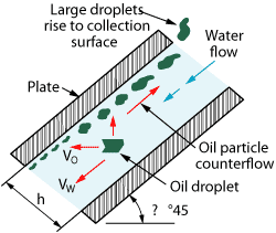
Closely spaced plates. Stokes’ law, as applied to skimmer tanks, states that the collection rate of oil droplets is directly related to the rising velocity of the oil droplets and inversely related to the distance they travel as they rise. In short, reducing the height that oil droplets must rise will enhance performance.
One method for reducing that height is the addition of closely spaced plates in the flowpath. This makes separation more efficient, allowing an increase of throughput without increasing the retention time required for separation, Fig. 1.
|
|
|
Fig. 1. Adding closely spaced plates within skimmer tanks increases separation efficiency by reducing the height that droplets must rise. Courtesy of Enviro-Tech Systems.
|
|
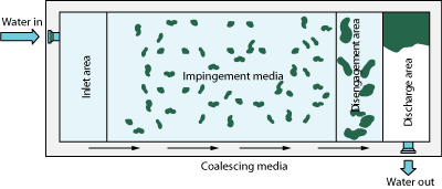
Coalescing plates. A second way to enhance efficiency is by adding coalescing plates at the inlet of the skimmer or CPI, Fig. 2. By design, the coalescing plate adds crucial surface area necessary for oil particle growth. This growth in turn increases the velocity of the oil droplets rising to the collection surface. Coalescing plates can triple the average size of oil particles, as determined in field studies. If coalescing plates are considered, a method to clean and remove them easily should be employed. When heavy concentrations of solids may be present, coalescing plates will plug, so other coalescing media, such as spheres, should be considered.
|
|
|
Fig. 2. Coalescing plates placed at the inlet of a skimmer tank or CPI can triple the average size of oil particles, which in turn increases the velocity of the oil droplets rising to the collection surface. Courtesy of Enviro-Tech Systems.
|
|
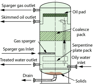
Spargers. A final method of enhancement, and perhaps the most practical commercially, is the addition of gas spargers, a technology developed within the last decade for improving water treatment equipment performance. Since gas is generally plentiful on an offshore platform, the sparger system becomes more practical than other enhancements.
Gas under pressure is pushed through a sparger tube to create minute bubbles flowing into the process as a method to efficiently remove the incoming oil. In a skimmer or CPI, this addition can be retrofitted to enhance the operation and to aid in handling increased process, Fig. 3.
|
|
|
Fig. 3. Gas spargers can be retrofitted to a skimmer or CPI to enhance performance and aid in handling increased water. Courtesy of Enviro-Tech Systems.
|
|
However, spargers require a clean environment for extended operation. Since the minutely porous gas tube contains very small openings, there is a tendency to plug over time. Scale and sludge tend to build up in the sintered tube, and over time they render the sparger tube inoperable. When this occurs, the tubes must be removed and cleaned much like a radiator is cleaned with caustic and acidic solutions. This is time consuming and somewhat costly, and in some instances can reoccur frequently, causing excessive downtime. If the process is generally clean, the sparger enhancement may work with infrequent cleaning, but if not, beware. With this choice, consideration should be given to having a spare set of spargers at the jobsite.
Solution for premature corrosion. A cathodic protection system can slow corrosion in skimmer tanks and CPI units, if it is properly sized and added along with a good internal coating system sufficient for the process. The protection system should be sized for a practical lifespan, and the anodes should be removable for future replacements and/or upgrades. Also, care should be taken to ensure that the anodes are not grounded to the bare area in the vessel. Such placement can shorten the lifespan of an anode, typically designed to last one to five years, by as much as 50%, by accelerating its sacrificial activity in the surrounding area. Thus, you could prematurely lose your corrosion protection, and would not know it without checking the electrical current in the tank.
For an anode to work properly, it should be completely submerged in the process liquid (not in oil) and it must be placed within the line of sight of the area it is supposed to protect.
Solutions for solids buildup. This problem has existed since the beginning of practical equipment design. Elaborate solids-removal processes have been designed in vessels but have had little success. This is generally because of poor vessel geometry and the lack of jetting systems in the design. CPIs are generally rectangular with sloped bottoms. Skimmer tanks are often rectangular and flat bottomed, though many new units are being built as horizontal cylinders. The edges and corners in the rectangular vessels are bypassed by fluid flow, allowing for sand and other solids to build up in those areas. This buildup creates an excellent environment for bacterial growth and, consequently, for corrosion. Bacteria that grow in collected solids also retain oil, which may affect the outlet oil content of produced water.
Obviously, vessel geometry cannot be changed by retrofit, so severe solids problems may be best solved by replacing rectangular vessels with cylindrical ones, which offer better solids handling because they don’t have edges or corners to collect solids, Fig. 4. Alternatively, substituting rectangular skimmer tanks or CPI units with sloped bottoms for flat-bottomed ones improves solids handling and processing even though they allow solids collection, because the solids fall to the bottom of the vessel, where they are easily removed.
|
|
|
Fig. 4. This flotation cell, manufactured by the author’s company, has a cylindrical geometry that avoids the problem of solids collection in edges and corners.
|
|
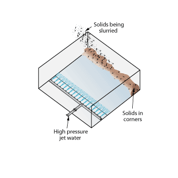
However, if replacing the vessel is not economically or technically viable, a retrofit alternative is to place strategically positioned jetting systems in or aimed at the corners and edges of vessel where solids collect. This will help to slurry those solids for removal, Fig. 5.
|
|
|
Fig. 5. Strategically positioned jetting systems in or aimed at the corners and edges of vessels where solids collect, to slurry those solids for removal, can be an effective retrofit for solids handling.
|
|
FLOTATION CELLS
Induced Gas Flotation (IGF) cells develop some of the same problems as skimmers and CPIs, including undersizing, premature corrosion and solids buildup, as well as others such as leaking hatches and oil removal complications.
Solutions for undersizing. IGFs can be characterized as either mechanical or hydraulic in their operation. The mechanical operation uses a mixing system to create the bubbles required for flotation. The hydraulic type uses a pump to create the bubbles. They require different solutions to compensate for undersizing.
Mechanical IGFs. The mechanical flotation cell is more difficult to add enhancements to than its hydraulic counterpart. The only enhancements that have been effectively applied to this type of IGF to improve processing capability and flowrate are enhancements to the agitator assembly itself. Because the agitator rpm, the impeller size and the retention time jointly determine the mixing process efficiency, there aren’t many variables to work with. Slightly increasing the rpm has enabled some operators to increase processing capability and hydraulic flow, improving efficiency.
The addition of spargers in the final cell has also been demonstrated to increase overall performance by producing super-fine bubbles to move any uncollected oil to the surface. This is an excellent retrofit for marginally operational units, where high water production (i.e., over capacity) has brought the unit to the edge of its operational efficiency. Spargers in the final cell can add 5-10% to the oil removal efficiency, which can often bring discharge under the legal limit in borderline cases. Spargers can be used in both mechanical and hydraulic units.
Hydraulic IGFs. Because hydraulic flotation cell efficiency is not generally sensitive to particle size, process enhancements are few. One of the most significant improvements is to hydraulically fine-tune the recirculation system. The design of most hydraulic IGFs in operation incorporates a direct relationship between the pump discharge pressure and the recirculation rate, which in turn is based on the incoming flowrate.
Some units boast a recirculation rate of 125% of the process design with a low-pressure discharge to conserve horsepower. This is actually a design flaw rather than a good design practice. First, the increased recirculation rate adds to the volume of water being processed in the vessel, which means retention time is decreased. Also, the combination of high recirculation rates and low discharge pressures does not provide good bubble characteristics in each cell. To reverse these conditions, therefore, becomes the improvement. Decreasing recirculation rates and raising pressures increases the retention time and improves bubble dispersion, increasing overall efficiency. This can usually be accomplished for an existing flotation cell, without increasing its size, but by a simple eductor retrofit.
Another cost-effective modification to the IGF is to improve gasification by increasing the number of bubbles per cross-sectional area of each cell. In short, the addition of multiple eductors in each cell can improve overall performance. This too can be carried out with commercial practicality. Generally, the internal piping can be changed easily to accommodate the installation of the additional eductors. The eductors can be designed with a quick-release feature for easy access and easy removal to facilitate maintenance.
Leaking hatches. A recent directive from the US Department of the Interior’s Minerals Management Service (MMS) requires examination of offshore equipment, including flotation cells, for gas leaks using an infrared video camera. This method pinpoints the exact location of a leak. This new regulation will reveal just how common the problem is in IGFs.
Some manufacturers attach vulcanized gasket surfaces to the hatch; other hatch designs have a channel frame for a removable sponge-like material. Both cases have their drawbacks. The vulcanized rubber is by far the superior material; however, after months of repeated opening and closing, the gasket begins to deteriorate rapidly, which can reduce its design lifespan (usually two years) by as much as 50%. Additionally, overtightening can create undue pressure on the gasket seal to the steel hatch, and either the elastomer will begin to crack or the steel portion of the hatch will begin to penetrate the elastomer. The end result of both problems is a leak that allows liquid to seep between the gasket surface and the hatch door, creating an environment for corrosion of the steel that is masked by the gasket. Thus not only is the lifespan of the gasket shortened, but the hatch itself is jeopardized.
Even if these problems do not occur, the hatch must be sent to the manufacturer when the gasket becomes worn to replace it. To avoid the downtime, many operators choose instead to replace the entire hatch as often as every two years.
Replacing the existing gasket with a removable elastomer gasket retains the material advantages of the vulcanized gasket while offering the ease of replacement associated with the sponge-like seal. One such removable gasket, designed by the author’s company, is cemented to the hatch door surface or can be retrofitted to existing gasket surfaces, eliminating the expensive necessity to replace the entire hatch door.
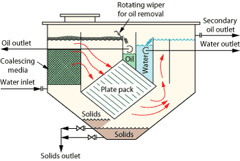
Oil removal issues. Most existing flotation cells feature a rotating wiper system to remove the floating oil collected in each cell, Fig. 6. This type of removal system is effective but requires considerable routine maintenance. The constant rotation of the wiper paddles places wear on the paddles, the paddle drives and the tank surface where the paddles make contact.
|
|
|
Fig. 6. The rotating wiper system used in many IGFs to remove oil requires considerable routine maintenance. The wiper system can be retrofitted to CPI units as shown here to move collected oil to the spillover weir. Courtesy of Enviro-Tech Systems.
|
|
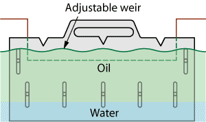
These maintenance requirements can be eliminated by replacing the rotating wiper system with an adjustable oil weir system. This design uses a series of adjustable weirs in each cell to facilitate spillover of collected oil from the mainstream flotation cell into the oil bucket with minimal water carryover, Fig. 7. While this option is especially relevant for new IGFs, the adjustable weir design can be retrofitted to an existing IGF in some cases. The weir-based design allows for independent adjustment of levels in each cell to account for any tilt introduced during the installation or even to prevent sloshing from roll, heave and pitch.
|
|
|
Fig. 7. An adjustable oil weir system facilitates spillover of collected oil from the mainstream flotation cell into the oil bucket with minimal water carryover, eliminating the maintenance requirements associated with rotating wiper systems. Courtesy of Enviro-Tech Systems.
|
|
Corrosion. Geometry plays an important role in reducing corrosion in flotation cells, just as in skimmer tanks and CPI units, so replacement is often a better solution to this problem than any retrofit. A cylindrical geometry is recommended for both corrosion resistance and greater structural integrity.
However, where replacement is not an option, cathodic protection should be considered along with a good internal coating as a retrofit to an existing unit. Designing the cathodic protection system as removable for future replacement and upgrades makes maintenance more practical.
Solids buildup. Solids are a condition of most processes and can be found in all aspects of produced water treating facilities, and especially in flotation cells. Because the IGF is typically the last step in the process for collection, solids tend to settle there. Typically, solids removal upstream of the IGF would be preferable, but sometimes this is not possible due to lack of retention time or poor chemical programs. Providing an outlet for solids in each cell with isolation valves and/or internal jetting is the best solution for their removal. Unfortunately, this is impractical for an existing flotation cell, and therefore is only available as a replacement option. The alternative is to shut down the vessel regularly for cleaning, which is done in most applications.
SAMPLING
|
|
|
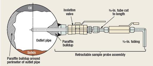
Fig. 8. To ensure a clean sample point, the sample probe assembly should be retractable for easy cleaning even while the discharge conduit is in operation.
|
|
One final consideration is effluent sampling. Sampling is a critical issue, especially when the effluent is close to the maximum discharge requirement. It becomes essential to make every possible effort to have a clean sample point, to eliminate the possibility of a contaminated sample. The sample point ideally should be placed in the center of the effluent conduit or pipe, keeping it off the bottom of the conduit to minimize the potential for contamination. Also, the sample probe assembly should be retractable for easy cleaning even while the discharge conduit is in operation, Fig. 8. A simple series of valves and removable fittings allow for this design. The combination of the above will ensure a proper sample point and a clean sample. 
|
THE AUTHOR
|
|
|
After 26 years as vice president of Engineering Specialties Inc., Frank Richerand started Enviro-Tech Systems in 1997 to offer repair and service of oilfield production equipment, as well as its own line of equipment, namely the Enviro-Cell and Enviro-Sep produced water treatment equipment. Mr. Richerand has taught short courses on produced water management at Tulane University and the University of New Orleans. He is the inventor of the Enviro-Cell three-stage oil-water separator. He can be contacted at frank@envirotechsystems.com.
|
|
|


