Designs must consider structural capacity, installation and thermal loads downhole.
Jueren Xie, Chengye Fan, Brian Wagg, Todd A. Zahacy, Cam M. Matthews and Yi Fang, C-FER Technologies, Canada
Steam Assisted Gravity Drainage (SAGD) is a widely used thermal method for in situ recovery of heavy oil and bitumen in Western Canada. While most SAGD applications completed to date have used slotted liners, Wire Wrapped Screens (WWS) have received increasing attention. Some operators have reported mixed results, but the screen’s large open flow area, design features, sizes and materials offer advantages. Given their relatively complex construction and limited design and application experience, there remains uncertainty about the design and implementation of WWS in SAGD horizontal wells.
For SAGD, WWS products need to have adequate structural capacity and serviceability for installation and thermal operation loads. Thermal loading will produce plastic strains, which can cause failure from fracture, low-cycle fatigue, localized buckling or collapse. This article presents several design considerations and guidelines for WWS, using non-linear finite element analyses to assess structural response and serviceability. It also focuses on the structural capacity of the base pipe and some of the key thermal-induced deformations of base pipe and the wire-wrap mesh.
SAGD PROCESS
SAGD consists of continuous, high-quality steam injection in an upper horizontal injector well and extraction of the condensed steam and mobilized fluids from a second lower horizontal producer well. This process results in fewer pressure/temperature cycles than cyclic steam stimulation, as well as lower injection pressures and temperatures. Because of these effects, SAGD has often been referred to as the “gentle” thermal process.1-3
Typical WWS design uses a Welded Wire Mesh (WWM) that surrounds and is attached to a perforated base pipe. A number of questions and uncertainties exist about WWS in SAGD:
- What are the design loads?
- What design criteria should be used?
- What is WWS’s structural capacity and serviceability?
- How can characteristics be evaluated?
- What are the critical design aspects?
- How may designs be improved or optimized for SAGD?
BACKGROUND
SAGD wells are completed with sand control devices in the horizontal section. Several of the early SAGD pilots,4-11 including the benchmark AOSTRA UTF pilot project,4-6 used various forms of WWS and WWM-type screens. A robust sand control system was desired for these pilots since earlier projects were impaired by sand production.4
For many early SAGD pilots, WWSs were selected over other methods because:
- WWSs were available in a wide range of sizes and designs
- Radial flow losses and differential pressures across WWS may be less than other devices
- WWSs were effectively used in a wide range of primary and enhanced recovery applications
- In the mid 1980s, slotted liner manufacturing methods were unable to produce liners with sufficiently small slot dimensions and tolerances
- Screens had demonstrated acceptable structural integrity and serviceability in SAGD.
Some early SAGD pilots required sand cleanouts and repair workovers to maintain operations.7,12,13 These were attributed to damage resulting from inadequate hole size, straightness or condition; improper installation; and improper startup and operating practices. Some authors have noted that, while WWSs have good torsional capacity, large temperature variations subject WWS components to severe thermal-induced cyclic loads in a corrosive environment.13
Slotted liner manufacturing, design and application experience have increased significantly since the mid-1980s. In addition, slotted liners are a robust, simple design and a low-cost alternative to screens.14,18 Today, there is growing operator interest in using WWS because some SAGD operators have experienced failures and excessive sand production in wells with slotted liners, and some SAGD operators report that WWSs have demonstrated good performance, serviceability and reliability.14-16 The background, load conditions, analysis approach and the results presented in this article may provide design insights for other SAGD sand control methods.17,18
WIRE WRAPPED SCREENS
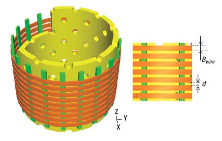
WWM consists of a wire that is wound spirally and welded to longitudinal ribs forming a cylinder with controlled spacing, as shown in Fig. 1. WWM is often fabricated with wedge-shaped wires from corrosion-resistant alloys. This produces a single, continuous, keystone-shaped helical slot with a large slot-area for flow and good structural rigidity. The large slot taper helps preventing plugging and sand bridging within the slot. The WWM is permanently attached to a base pipe, which has holes drilled through its wall. The base pipe provides structural support and extends beyond the WWM for machined connections.
 |
|
Fig. 1. Wire wrapped screen is formed from a wire that is wound spirally and welded to longitudinal ribs.
|
|
If d is the spacing between two adjacent wires, and Bwire is the wire OD width, then the WWM’s open area ratio (bWWM) can be defined:
Assuming the open area ratio for the base pipe is bpipe, the minimum open area ratio (b) for screen design can be defined as:
WWSs are designed such that the perforated base pipe’s open area ( pipe) is typically larger than that of the WWM (WWM). This is done so that flow losses through the base pipe perforations are less than the flow losses through the WWM. Hole size and pattern also need to be considered. Relative to slotted liners, which have flow areas of 1.5% to 3% of the outer pipe surface, the flow area through WWM is about 7%, while the base pipe open area is typically larger. In addition, the closer WWS slot spacing, relative to slotted liners, may reduce potential flow losses due to flow convergence effects.19,20 Stainless steel or other alloys may also allow WWS to offer better erosion and/or corrosion resistance.20 pipe) is typically larger than that of the WWM (WWM). This is done so that flow losses through the base pipe perforations are less than the flow losses through the WWM. Hole size and pattern also need to be considered. Relative to slotted liners, which have flow areas of 1.5% to 3% of the outer pipe surface, the flow area through WWM is about 7%, while the base pipe open area is typically larger. In addition, the closer WWS slot spacing, relative to slotted liners, may reduce potential flow losses due to flow convergence effects.19,20 Stainless steel or other alloys may also allow WWS to offer better erosion and/or corrosion resistance.20
In slotted liners, sand control and structural capacity are provided by the slotted pipe material. WWSs are more complex, multi-component sand control systems where structural capacity is provided by base pipe and sand control is from WWM. Little analysis or testing has been reported on WWS design and qualification for thermal horizontal well applications.
FIELD CONDITIONS AND DESIGN LOADS
During installation into a SAGD horizontal well, the liner is subjected to axial tension and compression, bending and torque. Axial loads come from drill collars and screen joint weight above a liner segment, and from any pull-down jacking force from the rig, to a maximum of about 400 kN, as the string is “pushed” into the horizontal section.
Curvature loading is imposed as the liner is forced through the build section with a maximum curvature of up to 15°/30 m. The liner’s localized curvature can exceed the average wellbore curvature when it is subjected to axial compressive loading. Therefore, it is prudent to consider liner curvatures that are somewhat larger than the planned wellbore curvature in the evaluation. Also, a liner may be subjected to torque during makeup and installation with a top drive.
During a SAGD well’s life, the liner will be subjected to thermal-cycle loading from operational shutdowns and well workovers. Liner behavior under thermal loading conditions will depend on the load state following installation and the nature and timing of the confinement conditions. Liner design should also consider the external pressure resulting from interaction between the screen and formation.
DESIGN CRITERIA
Screens should have sufficient structural capacity to sustain installation and operation loads, and maintain serviceability requirements. Base pipe structural integrity under installation and operational loads needs to be assessed.
Opening of wire gaps can reduce a screen’s function. Also, the injection and/or production efficiency of a well pair can be affected by mesh plugging and/or wire gap closure. A limit value of 25.4 microns (i.e., 1/1000 in.) for mesh opening/closing deformations is proposed.19,20 This is a 17% change for screens with a 0.152-mm (0.006-in.) gap width and 8.3% change for screens with a 0.305-mm (0.012-in.) gap width.
SCREEN STRUCTURAL CAPACITY
The structural design of a perforated base pipe includes specification of casing size, weight, grade, perforation density, hole size and pattern. Finite element analysis is well suited for WWS design. An example will demonstrate the approach.
Consider a 177.8-mm (7-in.), 38.7-kg/m (26.0-lb/ft) L80 base pipe with 132 holes per foot (hpf), and two different perforation sizes, 12.7 mm (0.5 in.) and 25.4 mm (1.0 in.). Assuming that Bwire is equal to 2.3 mm (0.09 in.) and d is equal to 0.305 mm (0.012 in.), then from Eq. 2, the open area ratios are 10% and 12% for the 12.7 mm and 25.4 mm perforation cases, respectively. The thermal conditions ranged from 20°C to 275°C.
Casing material was modeled using an elastic-plastic relationship.21,22 The model was temperature and strain-rate dependent to capture the strain relaxation effect at elevated temperatures, and was developed using data from several material coupon test programs.23 Previous stress analyses of a flat plate with a hole under tensile loading demonstrated that the stress concentration around a perforation increases with smaller hole size.24
Installation loads. One of the design objectives is to ensure that the base pipe and screen components remain elastic under the installation loads. Stress concentrations will occur around base pipe perforation edges,24 and it is necessary that the magnitude of any localized plastic strains is minimal.
The localized perforation strain will be a few times higher than the average strain applied to the base pipe. If axial tensile or compressive loads are controlled to below 30% of perforated pipe yield limit as a requirement to prevent liner lateral buckling in the wellbore,22 it is unlikely that the stress around the perforations will exceed the yield limit, or even if they do, plastic strain levels should be very small. On the other hand, it is important to ensure that a perforated base pipe has a sufficient axial loading capacity to sustain the installation jacking force. Analysis demonstrates that 30% of yield capacity for the base pipe design with 132 hpf of 25.4-mm (1.0-in.) hole size may be less than the maximum jacking force of 400 kN. For this consideration, lower hole density design may be preferred for larger hole size designs.
A wellbore curvature of 15°/30 m will impose an average flexural strain of 0.08% to the 177.8-mm base pipe. This flexural strain does not cause any concern.
One of the more common concerns is a liner’s torque capacity. Figure 2 presents the torque-turn relationship; the initial responses between the applied torque and resulting turns are almost linear for perforation hole sizes up to 0.16 turns. The torque capacities are 93.7 kNm and 51.2 kNm, respectively, for base pipes with 12.7-mm and 25.4-mm hole diameters.
 |
|
Fig. 2. The torque-turn relationship for L80 base pipe shows there will be a reduction in torque capacity as the size of the base pipe hole is increased.
|
|
This model shows that, for the same hole density and pattern, there will likely be a substantial reduction in WWS torque capacity as the size of the holes in the base pipe are increased. As a design requirement, the base pipe torque capacity should be well above the maximum specified makeup torque for the liner connections. This example illustrates that torque capacity should be given special attention when using large perforations.
Despite reduced torque capacity, larger perforations may actually reduce peak plastic strain at the base pipe perforations, as shown in Fig. 3. For the same number of turns, plastic strain in the 25.4 mm perforation case is much lower than in the 12.7 mm case. This suggests smaller perforations may cause more severe stress/strain localization around the perforations. For the case of large 25.4 mm diameter perforations, the torque capacity of the base pipe is significantly larger than the typical maximum installation torque loads for this liner.
 |
|
Fig. 3. Plastic strain for L80 base pipe under torque suggests that smaller perforations may cause more severe stress/strain localization at the perforations.
|
|
Operation loads. One of the critical thermal loading cases occurs when the liner becomes fully constrained axially. When this occurs, a temperature change will cause the development of axial loading.21,22 Where the axial constraint develops prior to initial heating, Fig. 4, the general base pipe response to a thermal cycle with the temperature varying from 20°C to 275°C and back to 20°C can be explained:
1. During initial heating, the liner material is compressed elastically until the elastic limit is reached near 200°C
2. Further heating leads to plastic deformation from constrained thermal expansion
3. As the temperature is held constant at 275°C, stress relaxation occurs from creep strain
4. As the confined liner cools, the axial load gradually becomes tensile.
 |
|
Fig. 4. Plastic deformation for L80 casing during heating changes to tensile loading after cooling.
|
|
Figure 5 shows plastic strain development at perforations over the full thermal cycle. Maximum plastic strains of 1.23% and 0.27% occur at the end of a thermal cycle for 12.7 mm and 25.4 mm holes, respectively. Strains develop in the diagonal webs between the holes from shear stresses in the webs, and some of the plastic capacity is from complex load transfer and non-linear deformations (outward bowing near the holes). These strain levels are considerably lower than the critical values that cause material fracture initiation around the perforations. Therefore, there do not appear to be any structural concerns for these two designs.
 |
|
Fig. 5. Plastic strain in L80 base pipe under thermal-cycle loading shows that maximum plastic strains develop in the webs between the holes.
|
|
Thermally-induced strain localization may occur at high temperature within segments or joints along the liner length.19,20 If this occurs, additional compressive strain can be transferred from “stronger” sections of the liner to the “weaker” sections. Peak plastic strains in the 25.4-mm perforation case remain much lower than those for the 12.7-mm design. At 3% additional joint strain, for example, the local plastic strains are 3.29% and 14.4%, respectively.
External pressure. External pressure can act on the WWS surface from formation loading. One of the objectives for WWS structural design is to make sure that external pressure will not cause liner collapse failure.
Figure 6 presents the relationships between external pressure and base pipe ovality for the two cases. The maximum pressure that the base pipe can sustain indicates WWS collapse resistance. These limits are 35 MPa and 24.2 MPa for the base pipes with 12.7-mm and 25.4-mm perforation sizes, respectively. These loads are higher than the overburden and fracture pressures of most SAGD applications (22.6 kPa/m in Alberta Heavy Oil IRP,25 20 MPa at about 885 m). While larger perforations reduce collapse resistance, the peak plastic strain levels in the 25.4-mm case remain significantly lower than in 12.7-mm case, Fig. 7.
 |
|
Fig. 6. Pressure vs. ovality for L80 base pipe shows that larger perforations reduce collapse resistance.
|
|
 |
|
Fig. 7. Plastic strain in L80 base pipe under thermal-cycle loading shows that maximum plastic strains develop in the webs between the holes.
|
|
A base pipe design that minimizes strain localization effects and limits plastic strain levels under thermal-cycle loading may diminish the potential for localized material fracture or low-cycle plastic fatigue failures. Larger perforations may be advantageous over smaller ones from this perspective. However, the results show that this advantage is offset by a reduction in torque and collapse resistance. The optimal configuration from this peak strain may be a smaller number of larger holes in the base pipe. Other load scenarios, other design elements (e.g., WWM to base pipe welds) and flow losses should also be considered in the design.
SCREEN SERVICEABILITY
One measure of screen serviceability is the magnitude of wire spacing opening or closing that develops under installation and thermal operation loads. The change in wire spacing is affected by the axial strain of the WWM and the thermal expansion/contraction of the wires during thermal operations.
WWM axial strain. The apex of the wedge-shaped wires commonly used in WWS is welded across the outer surface of the longitudinal ribs. Therefore, the axial strain on the WWM surface is developed mainly through rib deformation. The change in wire spacing (Δd) resulting from axial rib strain (´) can be determined by
where Bwire is the wire width and d is the original wire spacing.
For the example considered, the relationship between the wire spacing and WWM axial strain is shown in Fig. 8 as the linear diagonal line. If Δdcr is the critical wire spacing due to either gap opening or closing, beyond which the serviceability of the screen will be affected, the allowable WWM axial strain can be bounded by a box centered at the axes.
 |
|
Fig. 8. The relationship between wire spacing change and axial mechanical strain produces the allowable WWM axial strain boundary (red dashed-line box).
|
|
Given the suggested critical wire spacing change (Δdcr) of 25.4 microns, the allowable axial strain for this WWM example would range from 1% tensile to 1% compressive strain. Given the physical attachment of WWM to the base pipe, this WWM axial strain range also defines the allowable axial strain limits for WWS.
During installation, the axial tensile and compressive loads are usually controlled to less than 30% of the yield capacity of the base pipe material, the flexural strain due to a 15°/30-m wellbore curvature was only 0.08% for the 177.8-mm base pipe, and the base pipe axial strain levels under reasonable torque application would be even less significant. Therefore, typical SAGD well installation loads are of no concern for excessive wire deformations for the design considered.
Thermal expansion. Thermal expansion of WWM material due to a temperature increase will cause a change in wire spacing opening/closing. Two bounding situations were considered prior to temperature increase: radially unconfined wires and radially fully confined wires.
Several finite element analyses of the WWM model were performed. If WWM wire gap closing due to temperature change, Δdth, is defined by the thermal expansion of wire width, then the following approximate equations are proposed to determine wire spacing closing/opening due to thermal effects:
where ΔT is the change of temperature,  wire is the thermal expansion ratio of the material, and wire is the thermal expansion ratio of the material, and  is the Poisson’s ratio of the material. For 304L steel wire with a typical value of wire = 1.8 × 10⁻⁵/°C, and an average value of = 0.4, the wire spacing closing due to thermal expansion was determined, Fig. 9. The radially confined case will cause a larger wire spacing closure with increasing temperature, compared to the radially unconfined case. For example, with a temperature change of 255°C, the wire gap closure values are 10.3 and 14.4 microns for the radially-unconfined and radially-confined cases, respectively. Since these values are less than the proposed design threshold of 25.4 microns, it appears that the mesh design will meet the serviceability requirements. is the Poisson’s ratio of the material. For 304L steel wire with a typical value of wire = 1.8 × 10⁻⁵/°C, and an average value of = 0.4, the wire spacing closing due to thermal expansion was determined, Fig. 9. The radially confined case will cause a larger wire spacing closure with increasing temperature, compared to the radially unconfined case. For example, with a temperature change of 255°C, the wire gap closure values are 10.3 and 14.4 microns for the radially-unconfined and radially-confined cases, respectively. Since these values are less than the proposed design threshold of 25.4 microns, it appears that the mesh design will meet the serviceability requirements.
 |
|
Fig. 9. Correction to wire spacing change due to temperature variation shows that the radially-confined case will cause a larger wire spacing closure as temperature increases.
|
|
WWM axial strain absorption. During SAGD operations, if a liner joint yields due to constrained thermal loading, there is potential for the imposed thermal strains to localize in either weaker joints or at a weaker section of any given joint. Strain localization can cause much larger plastic strain in the shorter “weak” interval than the average thermal strain. This can lead to liner damage within the interval. A number of factors contribute to strain localization:
- Variations in material strength
- Variations in formation properties surrounding the liner
- Bending loads from formation movement.
High strain absorption capacity is desired for SAGD liner designs. The allowable WWM axial strain from Eq. 3 should be adjusted by the thermal gap changes (Δdth) from Eq. 4. The resulting allowable WWM axial strain boundary is shown by the off-axis red dashed line box in Fig. 8.
For the base case WWM design, the thermal corrections are 10.3 and 14.4 microns for the radially-unconfined and radially-confined cases, respectively. Therefore, the allowable additional axial compressive strains following thermal loading, are 0.60% and 0.44%, respectively. These are unlikely to cause any structural concerns for the base pipe. Therefore, WWS axial strain absorption capacity is mainly governed by the serviceability requirement and not the structural capacity of base pipe.
CONCLUSIONS
Operators are showing growing interest in using WWS products in SAGD well applications. However, they have questions about WWS design and qualification from structural and serviceability standpoints. Given the relative complexity of WWS and challenging operational environment, each WWS design should be qualified for the installation and operation conditions of the intended SAGD application.
For a given perforation density and pattern in the WWS base pipe, the hole size has a significant effect on the axial loading capacity, torque and collapse resistance capacity. When designing base pipes, an appropriate balance must be struck between minimizing flow losses through the screen, maintaining gap tolerances, and ensuring that the overall screen assembly has sufficient structural capacity to meet severe thermal well loading. The use of larger perforation hole sizes can reduce the peak plastic strains that develop around the perforations, and thus reduce the material fracture or low-cycle fatigue failure potential. For force-controlled installation load scenarios, it is important to ensure that a perforated base pipe has sufficient structural capacity to sustain jacking force and torque. However, for strain-based operational load scenarios, such as constrained thermal loading, larger perforations may be preferred.
WWM will typically have only a limited capacity for strain-absorption following thermal loading. Therefore, liner strings that incorporate screens should be designed and qualified to minimize strain localization. This will require careful attention to material selection and consistency.
Given the current limited understanding of the various design and operational issues related to the use of WWS in SAGD applications, additional analyses (e.g. alternative WWS designs, sizes, materials, load conditions, and specific design components, such as welds and the mesh-base pipe interaction) and full scale testing are warranted. 
ACKNOWLEDGEMENT
The authors thank C-FER Technologies Inc., Canada for supporting this work. This article was derived from WHOC 2008-389, which was presented at the 2008 World Heavy Oil Congress held in Edmonton, Alberta, Canada, March 10-12, 2008 and is used with permission.
LITERATURE CITED
1 Wagg, B. T., Xie, J., Understanding the mechanisms of well casing deformations; C-FER Final Report to Joint Industry Members, C-FER Project 99023, 2000.
2 Butler, R. M., Thermal Recovery of Oil & Bitumen, Prentice Hall, 1991.
3 Eindrick, T., Godin, M., Oil Sands Research and Development, Alberta Energy Research Institute (AERI), March 2006, p. 62 (http://www.aeri.ab.ca/sec/new_res/docs/OilSands_Private_Final_18May07.pdf, January 2008).
4 Edmunds, N. R., Wong, A., McCormack, M. E. and J. C. Suggett, “Design of horizontal well completions,” AOSTRA Underground Test Facility; 4th Annual Heavy Oil and Oil Sands Symposium, University of Calgary, Calgary, Alberta, Canada, February 18, 1987.
5 Edmunds, N. R., Kovalsky, J. A. and E. D. Pennacchioli, “Review of Phase A steam-assisted gravity-drainage test,” SPE 21529 in SPE Reservoir Engineering, May 1994, pp. 119-124.
6 Wells, D. G., Luhning, R. W., Dyck, R. G., Bohme, C. G. and R. Wasishima, “A tale of two wells: SAGD horizontal well wire wrapped sand control screen placement with mud circulation,” CIM 97-193 presented at SPE/CIM 6th Annual One-Day Conf. on Horizontal Well Technology held in Calgary, Alberta, Canada, November 12, 1997.
7 Chakrabarty, C., Fossey, J. P., Renard, G. and C. Gadelle, “SAGD process in the East Senlac Field: From reservoir characterization to field application,” UNITAR 1998.192 presented at 1998 UNITAR conference held in Beijing, China, October 27-30, 1998.
8 Saltukaroglu, M., Wright, G. N., Conrad, P. R., Mcintyte, J. R. and G. J. Manchester, “Mobil’s SAGD experience at Celtic, Saskatchewan,” paper 99-251999 presented at the CSPG Petroleum Societies Joint Convention held in Calgary, Alberta, Canada, June 14-18, 1999.
9 Athabasca ConocoPhillips Surmont SAGD 9460: Answer to well length question, Alberta ERCB 2006 in situ progress reports-Performance Presentations (www.ercb.ca/docs/products/osprogressreports/2006/2006AthaCPSmtSAGD9460_SurmontPilotWellCards.pdf, Jan. 2008).
10 Donnelly, J. K., “Application of Steam Assisted Gravity Drainage (SAGD) to Cold Lake,” CIM 97-192 presented at the SPE/CIM One-day conference on Horizontal Well Technology held in Calgary, Alberta, Canada, November 12, 1997.
11 Grills, T. L., Vandal, B. V., Ha:Um, F. and P. Trost, “Case history: Horizontal well SAGD technology is successfully applied to produce oil at LAK Ranch in Newcastle Wyoming,” SPE 78964 presented at SPE ITOHOS/ICHWT held in Calgary, Alberta, Canada, November 4-7, 2002.
12 Edmunds, N. R., “Investigation of SAGD steam trap control in two and three dimensions,” Journal of Canadian Petroleum Technology, Jan. 2000, Vol. 39, No. 1; pp. 30-40.
13 Hollies, D., Wadsworth, G. and W. Hariz, “Drilling practices for SAGD wells in the Athabasca oil sands,” 8th One-day conference on Horizontal Well Technology held in Calgary, Alberta, Canada, November 7, 2001.
14 O’Rourke, C., “Why would anyone still put wire wrapped screens in SAGD wells?,” CHOA Slugging It Out XV, 15th annual One-day Heavy Oil Conference held in Calgary, Alberta, Canada, March 26, 2007.
15 Koch, A., “Scaling/plugging issues in Husky’s Lloydminster thermal projects,” CHOA Slugging It Out XV, 15th Annual One-day Heavy Oil Conference held in Calgary, Alberta, Canada, March 26, 2007.
16 2007 Athabasca JACOS Hangingstone SAGD 8788, Thermal in-situ scheme progress report, Alberta ERCB 2007 in situ progress reports - Performance Presentations (http://www.ercb.ca/docs/products/OSProgressReports/2007/2007AthabascaJACOSHangingstoneSAGD8788.pdf, Jan. 2008).
17 “Full Steam Ahead: Baker Hughes,” Supplement to Oilweek Magazine, June 2006.
18 “FacsRITE for SAGD”, Absolute Energy Solutions (http://www.absoluteenergysolutions.com/WellCompletion/default.htm, Jan. 2008)
19 Kaiser, T. M. V., Wilson, S. and L. A. Venning, “Inflow analysis and optimization of slotted liners,” SPE/CIM 65517 presented at the 2000 SPE/Petroleum Society of CIM International conference. on Horizontal Well Technology held in Calgary, Alberta, Canada, November 6-8, 2000.
20 Ott, W. K. and Woods, J. D., Modern Sandface Completion Practices Handbook, first edition, Gulf Publishing Co., Houston, Texas, 2003.
21 Xie, J., Jones, S. W., Matthews, C. M, Wagg, B. T., Parker, P. and R. Ducharme, “Slotted liner design for SAGD wells,” paper 2006-416 presented at the First World Heavy Oil Conference held in Beijing, China, November, 2006.
22 Xie, J., Jones, S. W., Matthews, C. M, Wagg, B. T., Parker, P. and R.Ducharme, “Slotted liner design for SAGD wells - Staggered slot and gang slot patterns show better performance in FEA models than overlapping slot patterns,” World Oil, Defining Technology for Exploration, Drilling and Production, pp. 67-75, June 2007.
23 Humphreys, K. J., Solanki, S. C. And Link, R. A., Qualification of Grade-55 Casing for Thermal Recovery Service, C-FER final report for Joint Industry Members, C-FER Project 88-14, 1991.
24 Stress concentration factors, An engineers toolbox calculation module ETBX (http://www.engrasp.com/doc/etb/mod/fm1/stresskt/stresskt_help.html, Jan. 2008).
25 IRP Vol. 3: Heavy Oil and Oil Sands Operations, Drilling and Completions Committee, Jan. 2002 (www.enform.ca).
|
THE AUTHORS
|
|
|
Dr. Jueren Xie has over 13 years in engineering research and technical consulting. He has managed and/or played a lead technical role in numerous well completion designs for primary and thermal heavy oil operations, analysis and design of pipelines and offshore structures, and numerical analysis of steel, geomechanical structures and materials. He has authored and co-authored over 50 papers and over 100 technical reports. Xie is a Senior Drilling and Completions Engineer and a Program Leader at C-FER Technologies, Canada.
|
|
| |
Dr. Chengye Fan received his PhD in mechanical engineering at University of Alberta. Since joining C-FER in 2006, he has been involved in several numerical analysis projects, with a focus on casing, slotted liner, screen analyses and designs for SAGD well completions. Prior to his PhD study, he worked as a research engineer for Abaqus technical support in Abaqus Beijing Office. Fan is a Research Engineer with C-FER Technologies, Canada.
|
|
| |
Brian Wagg joined C-FER Technologies in 1990 and worked for over 15 years in C-FER’s Production Technology Department on primary heavy-oil operations, sand production management and heavy oil gathering system projects. He designs and qualifies connections and sand control for HPHT environments, and evaluates risk of unplanned releases from upstream well operations. Wagg is Manager of the Drilling and Completions department at C-FER Technologies, Canada.
|
|
| |
Todd Zahacy earned a BScs in mechanical engineering and biochemistry from the University of Alberta. He has over 15 years of experience in engineering and research consulting including: technical and economic assessments of SAGD well designs for low pressure and offshore application; artificial lift and steam injection control methods; thermodynamic-hydraulic modeling for production and injection well completion design and co-lecturer of a SAGD course. Zahacy is a Senior Consultant in the Exploration and Production Division of C-FER Technologies, Canada.
|
|
| |
Cam Matthews has over 25 years of experience in engineering and research consulting. He has managed numerous joint industry projects, holds four patents, has published numerous papers and is actively involved in SPE and other industry organizations. Matthews is the Director of New Technology Ventures at C-FER Technologies, Canada.
|
|
| |
Yi Fang focuses on analysis projects related to thermal well development, sand control, connection assessment and oil sand processing equipment. His research interests include numerical analysis, equipment mechanical design, and bio-mechanics. Fang is a Research Engineer at C-FER Technologies, Canada.
|
|
|


