The subsea chocking method uses polyurethane resin in a PVC-proofed nylon cover.
Leif Kowalski, Furmanite
The new chocking technology has been installed in a major subsea-installation project on StatoilHydro’s Oseberg Sør platform in the North Sea, to protect against conductor damage as part of an underwater-repair program. It is one of the latest developments in this technology.
Structural integrity issues surrounding aging offshore wells in the North Sea area-including the well conductor system (defined as the main outer structural tubular)-have driven a rising demand for subsea chocking as one method of protection from the fatigue effects of lateral wave movement. Conductor damage, a common problem on offshore platforms, has long been a topic for debate, as different causes are cited and as new solutions are tested. Many of the solutions, such as clamps, address the symptoms rather than the cause. Others, including the new chocking technology, have previously been restricted to topside use, but the latest developments have subsea applications.
INTRODUCTION
Various investigations, including transient dynamic analysis of a typical flowline and conductor, concluded that cracks and vibration observed on offshore platforms are caused by the fatiguing effects of the motion of the conductor and, in particular, the lateral forces of wave movement, which cause the high-frequency response of the conductor to bang or rattle inside its guide barrels.
Further research undertaken by Amec used Sesam (a DNV-developed finite element analysis structural model) to simulate the effects of wave loading on conductors and flowlines, and generate load-time histories for an irregular sea state, demonstrating how the loading manifests itself as a stress issue with corresponding wellhead displacement.
CHOCKING RESULTS
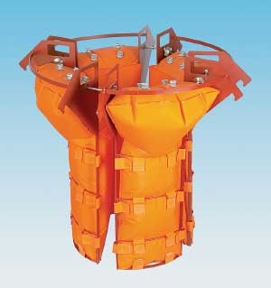
To reduce this fatigue problem, Furmanite teamed up with Amec to identify and develop a solution. Traditional options such as wooden wedges or rubber or plastic blocks can cause further problems by being too hard or by holding the conductor too rigidly. SmartShim consist of PVC-proofed nylon chocking slips filled with a polyurethane resin that is developed in-house (typically 80° shore-A hardness, oil, gas and seawater resistant). These chocks hold the conductor sufficiently firmly in place within the guides to prevent damage, while providing the necessary elasticity to absorb the wave energy effects, Fig. 1.
 |
|
Fig. 1. SmartShim chocks provide the necessary elasticity to absorb wave energy effects.
|
|
The material provides good abrasive resistance, allowing for the vertical movement of the conductor resulting from temperature changes in the riser content, and is ultrasonically welded for liquid tightness. Once set, the resin forms a resilient elastomer that is resistant to attack from most hydrocarbon liquids and gases, seawater and UV light, and requires no long-term maintenance. The cured material will withstand temperatures between -10°C and 80°C.
Because the gap between the conductor tube and guides ranges from 0.75 in. to 8 in. (and can be considerably more), and the conductor may not be centered within the guides, the chock’s resin is mixed and injected on site and is allowed to cure for about 24 hours to achieve full strength. This on-site casting means that the chock forms to fit the gap precisely, whatever the dimensions, and whether or not the conductor is centered within the guides.
Since the original development of the this technology, further evolutions have taken place, such as the introduction of a new pump skid that fully automates mixing and pumping of the resin on site for maximum precision and control. A range of resins has also been developed with varying hardnesses and densities to meet specific requirements, from applications where moisture or oil may be present to those that require low weight or a greater-than-usual degree of movement.
SUBSEA APPLICATION
Application of this chock technology on the StatoilHydro Oseberg Sør platform is a recent development. It was driven by the benefits of being able to minimize conductor movement to the lowest practical level, given the amplification of movement at higher levels and at greater distances from the original source.
The development required further research and analysis to account for additional criteria such as external water pressure, increased distances over which the resin has to be pumped from the deck of the diving support vessel, and the adaptation of subsea injection manifolds and venting arrangements. Extensive trials were performed before the first subsea installation, which took place on Shell’s Nelson platform in the UK sector of the North Sea. These confirmed that correct pressures had been identified, both to enable the resin to travel the distance through the 410-ft (125-m) high-pressure hoses and to counter the external water pressure effects at 49-ft (15-m) depth. They also confirmed that the filling of the new chocking slips with resin was properly achieved, and that the conductor would be satisfactorily stabilized.
Onshore installation trials were also performed with divers testing the fit-for-purpose equipment such as the support frames developed to help keep the chocking slips in place subsea while being filled with resin. These were designed to be in a cartridge and diver-friendly so that, with minor modifications, they could be deployed by ROV.
The application on the StatoilHydro platform in the Norwegian sector of the North Sea is the latest subsea application of the chock technology (Fig. 2) where the operator experienced problems on the conductors caused by wave-induced displacements inside the guides. The installation was performed as part of an underwater-repair program, to protect the conductors from sustaining further damage. StatoilHydro’s Oseberg Field has been producing for two decades, and the company aims to ensure field life beyond 2030.
 |
|
Fig. 2. Subsea application of the new chock on StatoilHydro’s Oseberg Sør platform in the North Sea.
|
|
In this case, the new chocks were applied to 27 slots, at 49-ft (15-m) depth, involving a total of about 13,000 ft (4 km) of hoses, 10 t (9 metric tons, mt) of resin, and 33 t (30 mt) of equipment deployed from the diving support vessel by Acergy.
CONCLUSION
This is an effective solution to fatigue damage arising from excessive movement at the wellhead, with the potential to create substantial savings. Structural analysis of the conductors to predict failure and determine corrective actions is an essential part of the job. 
|
THE AUTHOR
|
| |
Leif Kowalski is sales manager at Furmanite Norway. He has been with Furmanite for three years, and has a 30-year background in the oil and gas and processing industries.
|
|
|

