Part 1-Recent developments are introduced in three major artificial lift categories: sucker rod pumping, progressing cavity pumping and gas lift.
James F. Lea, PL Tech LLC; Herald W. Winkler, Texas Tech University; and Robert E. Snyder, Consultant
Described here are 19 recent downhole and surface equipment developments from 13 companies. Part 2, in May, will introduce developments in Electrical Submersible Pumping (ESP) and other miscellaneous new artificial lift applications.
Sucker rod pumping has, in many cases, evolved from classic beam pumps to include tower-type units. It is the most widely used form of artificial lift, usually involving the application of vertical rod motions, but now also cable, to operate a downhole reciprocating pump. New technologies have focused on increasing downhole pump life and efficiencies, and on prevention of sand wear. Progressing Cavity Pump (PCP) systems are based on a surface drive rotating a rod string, which drives a downhole pump rotor operating within an elastomeric stator. Gas well deliquefying is the removal of liquid covering the producing formation to increase gas production. Gas lift uses downhole valves to inject annulus gas into the tubing under liquid columns, or under optional plungers, to reduce column density and drive liquids to surface.
SUCKER ROD PUMPING
Eleven recent technology advances introduce improved downhole systems and operational controllers.
Downhole plunger. The new Farr downhole rod-pump plunger from Bakersfield, Calif.-based Muth Pump has a unique design change that allows it to pump sand, coal fines and all other solids without sticking the plunger in the pump barrel, and keeps those abrasive solids from prematurely wearing out the pump.
Figure 1 shows a side-by-side comparison of the Farr plunger vs. a conventional API plunger. The plunger connector (or bushing in the API plunger) is moved from the top of the API plunger to the bottom in the new plunger. This one simple move made a great difference in downhole rod pumping.
 |
|
Fig. 1. The Farr downhole rod-pump plunger (right) features a plunger connector on the bottom and a tapered plunger edge to direct solids away from the plunger-barrel contact.
|
|
In the API plunger, the top connector or bushing is 0.060 in. smaller than the plunger, leaving a gap at the top between the connector and the pump barrel. This gap allows solids to be forced down and outward into the gap as the plunger moves up; this further allows the solids to get between plunger and pump barrel, thus wearing out the metal surfaces and/or sticking the plunger.
Moving the connector to the bottom of the Farr plunger and tapering the top inward eliminates these problems. Solids are forced inward to catch the fluid stream going up, keeping them out of the gap.
Rod pump controller. In the past, operators chose between load-and-position sensors and amperage modulation to control rod pump wells. Conventional Rod Pump Controllers (RPCs) used load and position to determine when to turn a well on or off, while Variable-Speed Drives (VSDs) used amperage modulation to vary motor speed. Weatherford’s new WellPilot controller offers the best of both options as it combines the accuracy of load-and-position measurement with the precision of a VSD.
The new controller uses continuous load-and-position indications to calculate pump fill correctly. The variable-speed control then slows or speeds up the pump motor to maintain the optimal level in the annulus. This minimizes backpressure on the reservoir, allowing maximum flow. It also prevents the fluid level from falling to the pumped-off level, where pump wear and damage are accelerated.
Combining conventional RPC and variable-speed technologies ensures that the well is pumped at the proper speed in changing well conditions. There is no need for sheave changes because the controller adjusts the pump speed based on current conditions. The controller assures that the motor provides proper torque to operate when fully loaded and that the motor or rods will not be over-stressed by surpassing user-defined limits. That eliminates the need to oversize the drive relative to the motor for pump startup.
Furthermore, the controller archives critical performance data that can be retrieved at the wellhead or through a SCADA interface for remote analysis and control. It contains an inferred production algorithm for total produced fluid measurement as well as a user-configurable data logger that stores data up to 30 days. The units are available in sizes that cover power ratings from 5 to 250 hp and work with both single- and three-phase power supplies.
Sucker rod connection. The unique API four-part design of Weatherford’s PRO/KC connection and the PRO/KC precision makeup unit increase working life and load-bearing capability far beyond standard three-part API connections. The new system provides unmatched strength and durability for beam and progressing cavity pumping applications.
Composed of two pins, one coupling and a center torque button, the four-part design creates a stable and rigid connection, Fig. 2. Under some load conditions, a typical API connection can allow movement among the pin shoulder, the coupling face and through the threads. This causes elevated dynamic loads, which can lead to pin failure.
 |
|
Fig. 2. The PRO/KC four-part sucker rod connection combines two precision-length pins and one coupling plus a center torque button to give optimal pre-load pin neck stretch.
|
|
The patented makeup method for the four-part connection increases its load-bearing capabilities and working life. Pins and couplings are machined to precise length and made up to the center torque button. Pre-load is confirmed by measuring actual pin stretch to reduce stress on both pin shoulders, on the pin noses against the center torque button, and on the coupling. Also, the connection provides optimal pre-load stretch of both pin necks. The result is a rod connection with superior stability in tension, torsion, bending and fatigue applications.
Sand-resistant rod pump. Harbison-Fischer of Crowley, Texas, has introduced a patent-pending sucker rod pump that has been successfully tested in the toughest sand production conditions and has outlasted previous pumps.
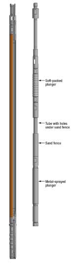
The Sand-Pro pump uses a proprietary method of dynamically separating produced sand from the pressure-sealing, leading edge of the primary sprayed-metal plunger, Fig. 3. By keeping these hard particles separated from the plunger/barrel interface, the surface of the primary (lower) plunger and barrel can seal the pressure longer and thus improve downhole run times.
 |
|
Fig. 3. The Sand-Pro dual-plunger downhole pump features an upper sand-handling plunger with soft packing that is pressure balanced to prevent sand entry and packing damage.
|
|
The pump uses two plungers connected in tandem to separate the upper-stage, sand-handling plunger from the lower-stage, pressure-sealing plunger. The upper, soft-packed plunger has no pressure across it to force sand into it and thus wear out the soft packing, while the lower, metal-sprayed plunger has no sand at its leading edge to wear it out. This gives the new pump the best conditions for each plunger’s function.
During operation, the lower plunger does not see any fluid flow at its leading edge because fluid only flows through its inner passage. On the upstroke, the lower plunger holds back the hydrostatic fluid pressure, but since liquid is relatively incompressible, there is no fluid movement to take sand into the space above the lower plunger.
For any fluid movement due to slippage, there is an integral sand “fence” above the lower plunger that traps sand and keeps it away from the chamber between the two plungers. It then directs the sand to rejoin the fluid flow by allowing it to fall back into the internal fluid stream on the downstroke through holes in the connecting tube. The soft-packed upper plunger provides the barrel-to-plunger sand seal above the lower plunger.
Cup plungers and composition ring plungers give good results for the upper plunger. These soft-packed plungers last longer than normal because they are not providing the high-pressure sealing function. The new pump is available in all standard configurations of sucker rod pumps that are compatible with soft-packed plungers.
Sucker rod lubricant. Upco, Inc., of Claremore, Okla., has developed a new sucker rod lubricant, Upco Rod Lube, the result of several years of planning, testing and developing circumferential displacement for sucker rods. Upco’s goal was to enable recommendation of specific displacement values for each diameter and grade of rods it manufactures.
Since lubrication for the pin-and-box connection is an essential component of proper makeup, the company started testing all known rod lubricants and a few alternatives. Two other companies offered to reformulate lubricants to meet field application and performance requirements.
The new Rod Lube met all expectations. The specially formulated lubricant, specifically designed for makeup and breakout, contains corrosion inhibitors and molybdenum disulfide to prevent thread galling, seizing and wear. It is smooth with no fillers. Tests showed increases of up to 40% in load-carrying capability with proper lubricant. The new product also ensures that connections achieve their design capabilities through proper makeup.
The product comes in a quart bottle that will lubricate 500 rod pins, and in a two-gallon pail for industrial applications. A small bead is applied to the pin threads only; the rod shoulder coupling face should remain dry. Upco has published a technical paper, “Lubricant selection using circumferential displacement of sucker rods.” The project uses core engineering concepts of stress, strain, torque and circumferential displacement, and it is completing initial phase testing, details of which are available.
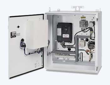
Variable-speed drive. Lufkin Automation of Houston has introduced a VSD combination package, the SAM VSD Well Manager. This unit has been designed to work in rod pumping applications in harsh environments. It is a packaged system that matches pumping to reservoir conditions, eliminating shutdowns, Fig. 4. Instead of traditional on/off cycling with pump-off controllers to match well performance, it keeps the well pumped down by continually adjusting pump speed, stroke by stroke. In addition, the system can change speed during a stroke to reduce rod float and other harmful conditions that damage the rod string and pumping system. Power ratings from 10 to 125 hp are available. The system has applications for both beam pumping and progressing cavity pumps.
 |
|
Fig. 4. The SAM VSD Well Manager, a new VSD combined-technology package, changes pump speed to match changing reservoir conditions.
|
|
Typical applications include: high failure wells; sanding/pump sticking; heavy crude/rod fall problems; steam-flood operations; low BHP; erratic production; and high volume, hard-to-pump-off applications.
Results have been impressive, with well failures reduced significantly. On heavy crude beam wells with rod-float conditions, production has been increased with reduced rod float and full pump stroke gain. Many traditional beam wells are increasing production by keeping the well pumped down.
Most PCP applications have shown increased production, as operators normally do not pump off the PCP to prevent pump damage. Some electrical savings have been seen, but many test wells have had a traditional rod-pump running time of less than 75%, so running a VSD for 24 hr a day did not net power savings, but was more efficient. Some operators choose to use a National Electrical Manufacturers Association (NEMA) B motor instead of the traditional NEMA D. The B has less slip and reduces power consumption with its higher efficiency.
Low volume, gassy well pump. CDI Energy Services of Tyler, Texas, introduced the newest design in the McGiver rod pump family, the MG-3. When faced with low volumes and/or gassy well conditions, the McGiver MG-3 rod pump can make the seemingly impossible possible. It is engineered to hold the hydrostatic load above the compression chamber, while creating a low-pressure area on the downstroke, above the lower plunger. The design also cushions fluid pound and keeps solids from settling inside the pump while idle.
With numerous successful installations in the Vernal, Utah, area, CDI is deploying the MG-3 into other markets where gassy/foamy production and low volumes are challenging operators. Current-installation, base pump depths range from 3,800 to 11,000 ft and, to date, the pump has only been installed in an insert pump configuration.
Particulate removal. Eagle Innovations Inc. of St. George, Utah, launched the Cyclone Plunger and the Cyclone Pump System. The new tools allow sand, grit, iron sulfide and other fines that contaminate produced oil and water to pass quickly through the pump assembly. Residual concentrations of these particulates are not allowed to collect between the barrel and the plunger.
Clearance between conventional pump plungers and barrels permits some fluid bypass, or slippage, between these surfaces. Within this void space, particulates can accumulate. During normal up-and-down plunger motions, these accumulations cause rapid wear, typically as vertical scoring, to both plunger and barrel surfaces. Moreover, frictional forces generated by these accumulations cause excessive stresses throughout the pump and rod string, which often result in a stuck pump, automatic pumping unit shutdown, or a parted rod string.
By incorporating the new system within the pump assembly, stuck plungers and premature barrel and plunger surface wear can be eliminated, and costly well servicing and pump replacements can be minimized.
During the downstroke, the pump, along with the Cyclone Seat Plug, forces any entrained particulates collected between the barrel and the plunger inward through the axial evacuation ports and into the plunger center, Fig. 5. Here, they commingle with other liquids entering the pump and are displaced into the tubing. Throughout the upstroke, particulates are also collected within the tapered neck of the plunger where, during the downstroke, they are flushed upward and enter the tubing through the top plunger adapter.
 |
|
Fig. 5. The Cyclone Pump System, operating above an API plunger, moves particulates into the plunger ID and then flushes them out into the produced wellstream on the upstroke.
|
|
Failure diagnosis. One of the leading causes of failure in sucker-rod-pumped wells is wear in rod parts and tubing. Failure of this common artificial lift system substantially raises lifting costs. To help minimize this problem, R&M Energy Systems of Willis, Texas, introduced VisuWell, a new failure frequency diagnosis and reduction system that images rod-pumped producing wells.
Typically, an operator has little reliable data regarding tubing deviation and regarding the root cause of rod-on-tubing wear, and of tubing or sucker rod failure. Obtaining information during well workover-such as tubing geometry, wall thickness and rod condition, correlated by depth-is critical to determine the root causes of failure.
VisuWell uses high-resolution data and internet-based imaging of key producing well conditions to enable efficient analysis and apply preventive measures before the workover is completed.
The diagnostic system can view failure history locations and map common data points from wellbore to wellbore. The rod string, tubing string and tubing deviation can all be evaluated before the well is put back on production. The system correlates rod and tubing condition and well deviation into an integrated, online wellbore profile for anyone in an organization to see. This allows a reservoir management team to collaborate efficiently, regardless of location.
An application is launched from a web browser that allows dynamic 3D viewing of individual wells or entire fields. Tubing and rod geometry, and condition by depth in the producing well, are downloaded to the client machine from a web server in compressed XML and then imaged in an interactive graphic format. Correlation of deviation, wear and failures is rapidly displayed in a 3D image of a specific well or a field view. Cross-wellbore queries allow mapping of common well conditions.
The net results are lowered failure frequency and lifting costs, and increased annual production.
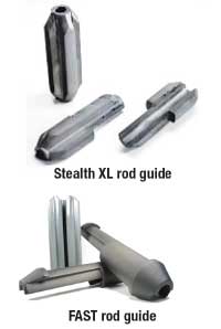
Field-installed rod guides. One of the most significant factors influencing productivity in rod-pumped wells is tubing wear prevention. Tubing wear affects horizontal, directional and slant well completions, as well as older conventional completions.
R&M Energy Systems offers a range of accessories, including two new rod guides, designed to effectively distribute wear evenly around the entire tubing string, or eliminate it completely. These rod guides can be installed in the field, eliminating the need to remove the rods from the wellsite, which reduces costs and returns the rods to service more quickly.
The Stealth XL high-performance field-installed rod guide offers a sleek profile for tough downhole conditions and is rated to 400°F, Fig. 6. Deep concave channels and a streamlined shape give this rod guide excellent flow characteristics in high-volume wells. The wide vanes provide outstanding bearing surface area for wear protection on rods, rod couplings and tubing in deviated wells.
 |
|
Fig. 6. Two new field-installed sucker rod guides, the Stealth XL and the FAST (Field Applied Spin-Thru) rod guide, reduce tubing wear and operating costs and increase tubing life.
|
|
The system’s proprietary rod coupling material provides superior holding power, which combines with mechanical locking mechanisms to allow the field-installed guide to withstand forces that move other field-installed guides out of position.
The FAST (Field Applied Spin-Thru), the other new rod guide from R&M, has an outer, “stator” portion not bonded to the rod, whereas guides for conventional rod strings are of one piece and bonded to the rod. The FAST rod guide’s unique three-fin stator remains stationary as the field-applied rotor/inner sleeve spins freely inside the stator. This loose fit between the rotor and the stator provides large flow passages to keep debris, such as sand, purged from the guide.
The tool is composed of one stationary sleeve that centralizes the rods inside the tubing and two locking pieces, Fig. 6. Each of the locking pieces slips over the sucker rod, creating a friction lock with the rod. This design reduces the pressure drop of the fluid flowing around the guide as well as the torque generated by mechanical and hydraulic friction in rotating rod strings.
PROGRESSING CAVITY PUMPS
Five advances in PCP technology have been introduced by two companies.
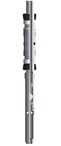
PCP-locking system. Caledyne Ltd. of Aberdeen offers the Snap In Snap Out (SISO) insert PCP-locking system for use with a Weatherford Arrowhead-type PCP for single-trip installation, Fig. 7. The nipple is installed as part of the tubing string, with the lock made up to the PCP. The lock-and-stator assembly hangs off the rotor arrowhead, and the insert assembly is run into the nipple until it lands on the no-go.
 |
|
Fig. 7. The Snap In Snap Out (SISO) axial PCP lock, run on tubing string, provides single-trip installation and retrieval of the insert PCP.
|
|
Downward movement locks out the keys and releases the arrowhead. The rotor then tags the tag bar below the stator. After the rotor is pulled up in accordance with standard operating procedures, the PCP is ready to run.
Re-engaging the arrowhead with the inner mandrel releases the lock, allowing the full assembly to be pulled out of the hole. The design of the SISO lock allows it to be re-seated in the nipple without being pulled out of the hole, to facilitate drive-head makeup to the rod string.
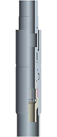
PCP sealing anchor. The Caledyne Ltd. PCP Sealing Anchor provides a reliable downhole seal and anchor installed directly below a PCP stator. It is well-suited for insert-type PCPs, allowing the assembly to be run in one trip.
The anchor works by applying pressure to the tubing or casing string above the assembly, against the internal ball seat, Fig. 8. The sealing anchor uses a swab-cup seal design, slowing the tool to be set with low pressure, which is field adjustable. Increased pressure allows the ball seat to shear or, alternatively, the ball can be allowed to float in the flow, allowing fluid bypass with minimal flow restriction. The sealing anchor is retrieved by a straight pull on the stator.
 |
|
Fig. 8. Caledyne’s PCP downhole sealing anchor is installed in one trip, setting bi-directional slips by applied tubing or casing pressure.
|
|
Anti-rotation PCP anchor. The Caledyne WL-5 Anchor is a wireline-deployed anchor used in conjunction with a plug to provide a non-rotating anchor point for a PCP stator assembly. In addition, the anchor provides a seal between the PCP inlet and the annulus.
The anchor is deployed as part of the stator assembly. It bottoms out on the plug and is locked in place by a downward jarring action. Latching into the fishing neck at the top of the stator and jarring upward retrieves the stator assembly.
Rod-driven PCP packing. Rod-Driven Progressing Cavity Pumping (RDPCP) systems are cost effective, efficient artificial lift alternatives for sand-laden fluids, gas wells or viscous oil. However, sealing mechanisms for surface drive heads and downhole rods can create environmental problems as well as unplanned downtime due to wear. RDPCPs are run by a drive rod, attached to the surface motor, that runs through the drive head and connects to the rods in the well. These systems must seal off the well at the base of the drive head to contain the well fluid.
The drive head is traditionally sealed with rope packing placed in a stuffing box, which is then compressed around the drive rod. This sealing device, however, requires some leakage to lubricate between the packing and the drive rod. To overcome leakage concerns and provide more robust options to eliminate downtime, Baker Hughes Centrilift has developed two sealing alternatives for its Lifteq drive head series.
Rotary seal. For environmentally sensitive areas, Centrilift provides a Rotary Seal Unit (RSU) to prevent leakage and help monitor RDPCP condition. Using a series of redundant seals and a leak-off port, field technicians periodically check the seal’s integrity.
Once the seals have become so worn that the leak-off port drips fluid when opened, an operator has two choices: 1) rely on the last redundant seal until a workover is scheduled, or 2) bolt down the RSU and convert it into a standard rope packing unit until the next scheduled maintenance. With this system, no unplanned walkovers are required, which reduces long-term operating costs.
Injectable packing. When a rope packing system starts to wear, it becomes compressed by well fluid pressure and gap pressure. To add more packing or change out the packing, the entire pumping system has to be shut down and allowed to backspin. This requires the operation to stop and production to cease.
The Centrilift Injectable Packing Unit, which is incorporated into Lifteq drive heads, alleviates this downtime. When packing gets compressed during operation, this injectable packing can be inserted while the drive head is still operating. To replenish the compressed packing, semi-liquid packing is inserted into a small port using a pressure gun. This new system reduces both downtime and the environmental impact of RDPCP systems.
GAS LIFT
Two companies offer a high-capacity mandrel valve, a below-packer delique-fying system, a downhole cable-to-surface monitor and a remote artificial lift monitor.
Side pocket orifice valve. Baker Oil Tools has developed the SurSeal High Rate orifice valve for standard side-pocket mandrels with 1½-in. pockets, and a high-capacity version with a 1¾-in. OD, for installation in a recently developed side pocket mandrel with that sized pocket. This valve has been developed for gas lift wells requiring high gas injection rates and improved operational safety.
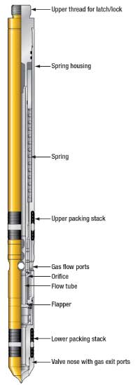
The valve is designed with a square-edged orifice that allows volume control of injected gas from the annulus into the tubing, Fig. 9. A flapper and seat, much like the one used in subsurface safety valves, prevents reverse flow communication back through the valve should tubing pressure exceed annulus pressure. When annulus pressure becomes greater than tubing pressure and gas flows through the valve, a pressure drop through a square-edged orifice moves a flow tube down across the flapper, both opening the valve to flow and protecting the flapper and seat from damage or erosion.
 |
|
Fig. 9. The SurSeal High Rate square-edged flapper orifice valve, for installation in side pocket mandrels with 1¾-in. pockets (as shown here) or with standard 11⁄2-in. pockets, has been developed for gas lift wells requiring high gas injection rates and improved operational safety.
|
|
The flapper/seat configuration eliminates the need for reverse flow checks and associated components to be located in the injected gas flow path. This enhances the valve’s gas passage capability compared with other orifice valves.
The new mandrel with the 1¾-in. pocket is designed for completions using 5½-in. tubing that requires extremely high gas injection rates for optimum production. In the past, side-pocket mandrels with dual pockets have been used to artificially lift this well type; however wireline operations to service these valves have been a challenge. With the mandrel that accommodates a larger orifice valve, high gas injection rates can be achieved through a single-flow control device, and wireline intervention, if required, will be greatly simplified.
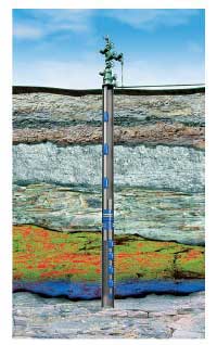
Gas-well liquid unloading. Schlumberger offers the PerfLift perforated-zone gas lift system, which addresses continuing demand for gas well liquid-loading solutions. This system allows placement of traditional gas lift valves below a production packer to reach deep into perforated intervals and unload liquid from the deepest part of the zone, Fig. 10.
 |
|
Fig. 10. The PerfLift gas-well liquid removal system features gas lift valves below a production packer to unload from deep in the producing zone.
|
|
Placing the valves below the packer enables gas inflow across long perforated intervals, maximizing reservoir drawdown and critical flow velocities. This relieves pressure on the lower producing zone and allows natural pressure to assist in unloading the well.
The gas lift system can be used in conjunction with cable-to-surface gauge technology to optimize lift-system and well performance. The system can be used intermittently or, where liquid loading is an ongoing problem; it can be used continuously to maximize production.
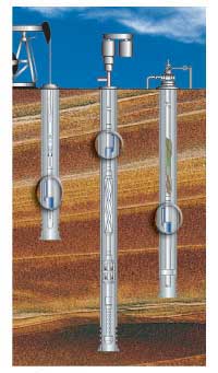
Downhole monitoring system. Schlumberger’s Phoenix Cable-To-Surface (CTS) digital downhole monitoring system is a cost-effective solution for monitoring gas-lift-, rod-pump- and PCP-lifted wells. This system is installed either above or below the lift system in a gauge carrier and communicates downhole pressure and temperature data to surface via an insulated clad encapsulated instrument wire, Fig. 11.
 |
|
Fig. 11. The Phoenix cable-to-surface downhole monitoring system communicates pressure and temperature to surface via insulated wire.
|
|
At the surface, a universal communication device collects, stores and transmits data. The surface device is designed to be flexible and to communicate with existing SCADA systems or connect through ancillary devices. Data can then be transmitted to a remote location to enable lift system diagnosis and optimization.
Reservoir optimization monitor. Also from Schlumberger, Advanced Lifting Services is a unique workflow originally designed for using downhole data collected from ESP-lifted wells to enable monitoring, control, surveillance, diagnostics and optimization, not only for the lift system, but also for well inflow in real time. Implemented in conjunction with the Phoenix monitoring system, the service has expanded workflows to include gas lift wells as well as wells lifted by rod pumps and PCPs.
The use of downhole data transmitted to a team of artificial lift and reservoir experts has enabled lift system diagnosis and optimization, as well as production optimization. Workflows have been developed to provide quick feedback and recommendations to improve well performance.
To maintain operational efficiency, the service will: define the most efficient window of operation for the well/asset and establish thresholds for trending well performance; manage wells by exception; track inefficiencies over time in the lift system; and provide proactive intervention and monitor impact on production. For field development, it can map permeability and pressure over time to understand drainage, and recommend infill drilling to improve recovery. 
|
THE AUTHORS
|
|
|
James F. Lea teaches industry courses in artificial lift and production for Petroskills. He holds BS and MS degrees in mechanical engineering from the University of Arkansas and a PhD in mechanical engineering from Southern Methodist University. He worked for Sun Oil Co. as a research engineer from 1970 to 1975, taught at the University of Arkansas from 1975 to 1978; was team leader of production optimization and artificial lift at Amoco EPTG from 1979 to 1999 and was chairman of Texas Tech University’s petroleum engineering department from 1999 to 2006.
|
|
|
|
Herald W. Winkler is former chairman of and now a professor emeritus and research associate in Texas Tech University’s petroleum engineering department in Lubbock, Texas. He works as a consultant in artificial lift, specializing in gas lift.
|
|
|
|
Robert E. Snyder, consultant, retired from Gulf Publishing Co. in 2006. He earned a BS degree in mechanical engineering from the University of Wyoming in 1957; served two years in the US Air Force; worked 10 years for Marathon Oil Co.; 29 years for GPC; and seven years for Completion Technology Co. Within GPC, he served as engineering editor and as editor of Ocean Industry and World Oil.
|
|
|


