Insulating packer fluid retains production-tubing heat after long-term shut-in.
Paul H. Javora, Xiaolan Wang, Qi Qu, Gary Poole and Shane Dunbar, BJ Services; Jack Sanford and Cristina Cordeddu, ENI Petroleum
Thermal insulating packer fluids have been widely used in deepwater completions. Undesired heat loss to the surrounding environment accelerates the formation of gas hydrate, paraffin and asphaltene depositions, which creates significant flow assurance concerns. Significant reduction in heat loss has been achieved using insulating packer fluids. Even greater heat losses are expected during normal shut-in operations and, in the event that an unexpected, long-term shut-in is required, heat retention capability of the insulating fluid becomes critical. Failing to properly design the insulating fluid can result in severe deposit of troublesome gas hydrates, paraffin and asphaltene, and even prevent the re-start of the well without assistance from chemical injection.
An insulating packer fluid was selected and applied to a deepwater project in GOM in order to prevent asphaltene/paraffin deposition, based on well profile analysis and produced hydrocarbon properties. Recently, this well had to be shut-in for more than 30 days to work on the Surface-Controlled Subsurface Safety Valve (SCSSV). Severe paraffin/asphaltene deposition was expected when the temperature fell below 90°F. Prior to the required workover operations, a temperature log at the SCSSV (7,500-ft TVD) verified that the resulting temperature remained above 90°F. A simulated wellbore temperature at 7,500-ft TVD was estimated to be 67°F. The insulating packer fluid placed in the annulus from mudline to 8,000-ft TVD had effectively maintained the temperature higher than the required temperature (90°F) during this long shut-in period.
INTRODUCTION
Flow assurance issues due to wellbore heat-loss problems have been recognized for more than 40 years. Various methods and techniques to overcome these problems have been reviewed1 and effective water-based insulating packer fluids1-6 have been used successfully in deepwater applications ever since late 1990. One company has completed more than 80 installations in the GOM. Various types of installations have included placement of a water-based insulating packer fluid in a single riser, in one or both annuli of a dual riser, and in one or more annuli below the mudline. In each case, the insulating fluid was used to prevent heat loss from the production tubing to the surrounding environment in order to prevent the formation of gas hydrate, asphaltene, wax or scale particles, and/or for the control of annular pressure buildup in outer annuli.
In addition to the standard heat-aged testing to determine long-term stability of an insulation fluid, explicit testing to determine the “effective thermal conductivity”5 of an insulating fluid for wellbore or deepwater riser applications, is indispensable. These test methods “convection.”1-4 Convection is one of the most important sources of heat loss in a wellbore or riser and the forces that create convection must be incorporated into the test methodology7. When these forces are not present or are minimized in the test methodology,8, 9 the “thermal conductivity” values that result, relate more closely to the “intrinsic thermal conductivity”5 of the fluids, and do not adequately define the impact of convection on heat loss within a wellbore or riser. An over-estimation of the fluid’s ability to control heat loss in a wellbore or deepwater riser therefore results.
INSULATING PACKER FLUID PROPERTIES
The 9.5-ppg water-based Super-Insulating Fluid (SIF) described herein was designed for long-term applications in wellbore or riser annuli. To avoid the potential for high-pressure crystallization of fluids at the low mudline temperatures experienced in deep water, the brine-based fluids used in this deepwater project, including the SIF, were formulated to have True Crystallization Temperatures (TCT)10,11 below 30°F (-1°C) and Pressure Crystallization Temperatures (PCT)10-12 below 30°F (-1°C) at 15,000 psi.
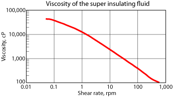
Water-based SIFs are viscosified to facilitate fluid placement at the desired location in the well. Since many applications place the SIF in the colder regions of the well or use it during colder winter months, the fluid must remain pumpable at ambient conditions using common oilfield equipment. One beneficial characteristic of the SIF system is its controlled viscosity that allows it to be placed into the well, and if required, the SIF can be pumped back out of the well as easily as it was pumped into the well. This ability to easily recover the fluid out of the well is desirable, especially when unforeseen and unexpected situations dictate its removal in order to rework the well, etc. This beneficial characteristic for insulating fluids appears to be unique in the industry, when compared with recently published work.9 The viscosity profile for the SIF is presented in Fig. 1. Fluid viscosity is controlled by adjusting one or more of the system components.
 |
|
Fig. 1. Rheological Profile for super-insulating fluid.
|
|
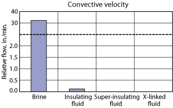
Another important attribute of super-insulating fluids is the ability to control convective velocity. The convective velocity of the SIF is compared to brine, a typical insulating fluid, and a cross-linked fluid in Fig. 2. Specific chemical additives included in SIF formulations allow the fluid to effectively control convective currents, and compares favorably with the patented cross-linked water-based insulating fluids developed in 2003.
 |
|
Fig. 2. Comparison of convective velocities for brine and the insulating fluids.
|
|
The thermal insulating quality of SIF’s has been described in several publications.1-6 Importantly, the heat transfer coefficient U (in unit dimension BTU/[(hr) (°F) (ft2)]), and “thermal conductivity” values that have been reported were determined for oilfield wellbore environments wherein a meaningful, measurable temperature differential in the vertical direction was established; that is, a significant temperature variation existed from bottom to top in the simulated wellbore.
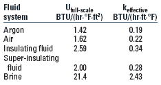
When this condition is achieved, the measured “thermal conductivity” value has been termed the “effective thermal conductivity”, keff, a value that more clearly represents heat loss within a wellbore environment. The unit dimension for keff is the same as for the “intrinsic thermal conductivity, BTU/[(hr) (°F) (ft)], but keff is determined under dynamic conditions including convection within a simulated wellbore. Values for the heat transfer coefficient, U, and the effective thermal conductivity, keff, are presented in Table 1. The effectiveness of the SIF approaches that of air and argon, significantly surpassing brine.
| TABLE 1. Heat transfer coefficients and effective thermal conductivities |
|
|
|
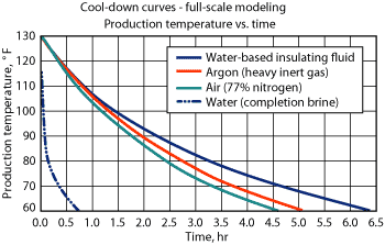
An additional SIF property pertinent to this case history is its ability to retain heat during shut-in periods. Compared to both air and argon, the SIF retained heat during shut-in conditions more efficiently than either gas. This in part is due to its comparatively high heat capacity and restricted convective movement compared to air or argon. Cooldown curves for brine, air, argon and the super-insulating fluid are shown in Fig. 3. While the brine quickly loses heat, the insulating quality of air and argon significantly retard the heat loss to the surrounding environment. As described, the SIF performed best of all.
DEEPWATER GOM CASE HISTORY
This deepwater GOM project was drilled in 3,900 ft of water to a total depth of 24,600 ft, with a bottomhole temperature of 197 °F. The synthetic oil-based drilling fluid was successfully displaced with a balanced displacement train using 12.5-ppg brine-based solids-free-surfactant cleaning pills to 10.5-ppg completion brine. After the well was perforated and completed, 10.5-ppg completion brine was used as the packer fluid. However, based on well profile analysis and analysis of the produced oil during the design phase for this project, severe paraffin/asphaltene deposition occurred when the temperature fell below 90°F.
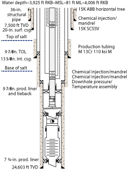
This information, coupled with potential for the formation of gas hydrates, suggested using the SIF to optimize flow assurance. Therefore, 9.5-ppg SIF was placed into the wellbore from mudline to 8,000 ft, which was 500 ft below the SCSSV. A schematic of the wellbore configuration is shown in Fig. 4. The well was subsequently completed subsea and put on production.
 |
|
Fig. 4. Wellbore schematic.
|
|
After producing for several months, a malfunction of the SCSSV, unrelated to fluids being produced or to completion fluids, was encountered. The well was shut in with production in the tubing. Due to logistics and rig events at the time, the well was not entered until after 77 days. During this time, cooling around the critical SCSSV was occurring continuously. Previously, it had been determined that the simulated wellbore temperature at 7,500 ft, the depth of the SCSSV, was estimated to be 67°F. The problem would be worsened by the formation of gas hydrates and deposition of asphaltene and wax.
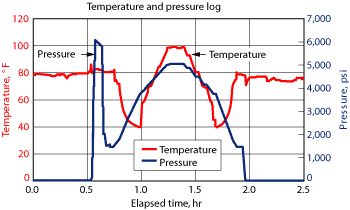
The workover riser was connected and 10.5-ppg brine was obtained and used for the workover operations. Methanol was continually used to insure that the system remained hydrate free. Prior to the required workover, duplicate temperature and pressure logs were run to the SCSSV at 7,500 ft TVD. When the tools were retrieved from the well, no deposition of any asphaltene or wax was evident. Only a teaspoon of solids was obtained from the tools, with a minor trace of asphaltene and wax. No indication of deposition was observed. The visual inspection results were substantiated by data obtained from the temperature logs, Fig. 5.
 |
|
Fig. 5. Temperature and pressure logs.
|
|
Pressure was applied to the tool at an elapsed time of 0.6 hr, tested to 6,000 psi, and then adjusted to 1,500 psi before the tool was RIH. As the tool entered the workover riser, the pressure increased until the SCSSV was reached at 7,500 ft at about 1.25 hr elapsed time. Pressure at this point was 5,000 psi and was attributed to the increased pressure due to the combination of completion brine, production fluids and methanol in the hole. As the tool was retrieved from the well, the pressure decreased to 1,500 psi when it reached surface and was removed from the riser.
The temperature log indicated a constant 80°F until the tool entered the workover riser at about 0.75 hr and decreased until the tool exited the riser and entered the tubing below mudline. At this point, the temperature increased until the SCSSV was reached, where it remained constant at 99°F until it was retrieved from the well, essentially following the reverse pathway until it reached surface.
Importantly, the measured temperature at the SCSSV was found to be 99°F, well above the 90°F required to prevent asphaltene and wax precipitation. This verified the presence of asphaltene or wax on the tools, and that none should be expected when the ambient temperature at the SCSSV was 99°F. This result also alleviated concerns that gas hydrates might have formed in and around the SCSSV. The SIF, placed in the packer annulus from mudline to the 8,000-ft TVD, had effectively maintained the temperature higher than that required (90°F) during the long shut-in period.
Since the SIF prevented the formation of gas hydrate, asphaltene and wax problems associated with the long-term shut-in, the SCSSV was replaced without needing a more substantial intervention.
The problem described in this case history was resolved without the need to remove the SIF from the wellbore, a task which could have been performed without difficulty. This would not have been the case with cross-linked insulating fluids that set to a rigid gel. For various reasons unrelated to this particular SIF, super-insulating fluids have been removed from several wells during workover, and subsequently reused on the same wells. This topic will be the subject of a future publication. 
ACKNOWLEDGEMENTS
The authors thank the management of ENI Petroleum and BJ Services Company for permission to publish this work. We also thank all of the operating and service personnel who contributed to this project.
LITERATURE CITED
1 Javora, P.H., et al., “Development and application of insulating packer fluids in the Gulf of Mexico,” SPE 73729 presented at the International Symposium and Exhibition on Formation Damage Control in Lafayette, Louisiana, February 20-21, 2002.
2 Wang, X, et al., “A new thermal insulating fluid and its application in deepwater riser insulation,” SPE 84422 presented at the SPE Annual Technical Conference and Exhibition in Denver, Colorado, October 5-8, 2003.
3 Javora, Paul H., Wang, X., Stevens, R., and R. Pearcy, “Water-based insulating fluids for deep-water riser applications,” SPE 88547 presented at the SPE Asia Pacific Oil and Gas Conference and Exhibition in Perth, Australia, October 18-20, 2004.
4 Javora, P.H., et al., “Managing deepwater flow assurance: Unique riser design allows dual annuli thermal insulating fluid installation,” SPE 96123 presented at the SPE Annual Technical Conference and Exhibition in Dallas, Texas, October 9-12, 2005.
5 Wang, X., Qu, Q., Stevens, R., and P. Javora: “Factors controlling the proper design of effective insulation fluids for oilfield applications” SPE 103132 presented at the 2006 SPE Annual Technical Conference and Exhibition, San Antonio, Texas, September 24-27, 2006.
6 Xiaolan Wang, et al., “New trend in oilfield flow assurance management: A review of thermal insulating fluids,” SPE 103829 presented at the 2006 SPE International Oil & Gas Conference and Exhibition in China, Beijing, China, December 5-7, 2006.
7 Willhite, G.P., Wilson, J.H. and W.L Martin, “Use of an Insulating Fluid for Casing Protection During Steam Injection,” J. Pet. Tech., November 1967), 1453 (SPE 1732).
8 Dzialowski, A., et al., “The development and application of environmentally acceptable thermal insulation fluids,” SPE/IADC 79841 presented at the SPE/IADC Drilling Conference, Amsterdam, The Netherlands, February 19-21, 2003.
9 A.M. Ezzat, et al., “High-performance water-based insulating packer fluids” SPE 109130 presented at the 2007 SPE Annual Technical Conference and Exhibition, Anaheim, California, November 11-14, 2007.
10 API Recommended Practice 13J - Testing of Heavy Brines, 3rd Ed., American Petroleum Institute, Washington, DC,2003.
11 ISO 132503-3 Testing of Heavy Brines, 1st Ed., International Organization for Standardization, Geneva, 2005.
12 Javora, P. H., et al.,“A New Technical Standard for Testing of Heavy Brines” SPE 988398 presented at the 2006 SPE International Symposium and Exhibition on Formation Control, Lafayette, LA., February 15-17, 2006.
|
THE AUTHORS
|
|
|
Paul H. Javora is the sr. research & technology engineer III for the Completion Fluids Group of BJ Services Company, Tomball, TX. His areas of expertise include completion and workover fluids, drill-in fluids, drill-in and drilling fluid displacements and cake removal, clear brine reclamation, wellbore insulating fluids, and corrosion. Prior to joining BJ Services, Paul worked in research and technical management positions for Dresser Magcobar and OSCA Inc., and has over 30 years experience. Paul holds BS and MS degrees from St. John’s University (New York) and a Ph.D. degree in inorganic chemistry from The University of Texas, Austin. Paul is a Member of SPE.
|
|
|
|
Jack Sanford is a deep water completions consultant currently working for Eni Petroleum in Houston Texas. Jack has worked with several operators over the last 18 years, including Exxon (Nigeria), Unocal, Amoco and Kerr-McGee. Sanford is a member of SPE and is a Registered Professional Engineer in the State of Louisiana. He graduated from Texas A&M University with a BS in both Geology and Petroleum Engineering, and a ME in Petroleum Engineering.
|
|
|


