SPECIAL FOCUS: DRILLING REPORT
Solving a major drilling challenge for a Latin America operator
Identifying the value of LWD information through telemetry drill pipe
Reginaldo Rodriguez, Pemex, Maximo Hernandez, IntelliServ, and Paul Hamel, Halliburton
The industry is well aware of the need for abundant, accurate and timely information and the intelligent drillstring is the conceptual extension to the operator’s surface network. The information transfer rate of such a drillstring at 57,000 bits per second (bps) well exceeds the 30 bps possible through a mud column.
This drillstring system permits real-time evaluation of reservoir quality, assuring that the well path tracks in the reservoir’s sweet spot. Additionally, intelligent drillstrings can be used in wells drilled with foam or air.
DRILLING WITH FOAM AND LOSSES
A recent experience in Latin America illustrates the value of this technology. A state-owned oil company, Pemex, recently finished drilling a difficult well using an interface between LWD, MWD, and Rotary Steerable System (RSS) tools from Sperry Drilling Services and a telemetry drill pipe system from partner IntelliServ Inc. The drilling team faced an expensive drilling problem: Pemex needed a high-angle, nearly 6,500-m well, to be drilled under very challenging conditions, in a mature, onshore field. “This is severe drilling,” according to Lino Vella-Gregory, Sperry’s country manager for Mexico. “The Cretaceous producing formation is abrasive, heavily faulted, with very high temperatures. Due to the danger of lost circulation, Sperry and Pemex elected to drill underbalanced with foam, which limits mud-pulse transmission of downhole information.”
Because the hole was filled with foam rather than mud, information about the directional well path was problematic. If the wellbore reached a lost circulation zone, Pemex would drill essentially blind for so many meters, stop, run a gyroscopic survey, adjust the azimuth and inclination of the hole, then drill another section. It was critical to run the wellbore into the sweet zone, but the “drill-survey-correct” approach was not satisfactory and could miss the target. Thus, expensive sidetracks were possible.
To control costs and to improve production, Pemex wanted to reduce/eliminate potential sidetracks. Wells in the area can cost as much as an offshore well. The risk of high-cost, non-productive drilling is high if the direction of the wellbore is not accurately controlled.
Solution proposals for this problem started a year and a half ago by establishing an interface between Sperry’s tools and IntelliServ. Halliburton decided to focus efforts on the interface-sub and downward, and to partner with IntelliServ on the wired components above. The tool, InSite IXO, takes real-time data from Sperry sensors and converts it to a signal that can be sent up the hole through wired drillpipe into the tool’s server on a rig. Down-linking over the network can control RSS tools.
Once a full well design was finished, a switch to telemetry drill pipe for the directional section was requested. Sperry was called-in as the MWD, LWD and RSS provider. Due to the high reservoir temperatures (300°F), on the first trip in the hole the telemetry pipe’s self diagnostic detected a weak, failure-prone component, which was changed. Tripping-in then continued.
When the well reached beyond 5,100 m, geosteering began on the high-angle portion with the tools transmitting downhole data to a Real-Time Operations Center in Villahermosa. This provided abundant, accurate and timely data to the operator’s engineers and decision-makers. Thus, they were able to continually monitor operations for successful and efficient drilling of the well.
Although expected, a total loss zone was not encountered in this well. Nevertheless, drillstring telemetry continued to work throughout the zone where vibration was high. At least one telemetry tubular (a heavyweight) buckled and was damaged beyond repair by vibration. Although the tubular was physically damaged, it never interrupted data flowing through the telemetry components.
Due to a minor telemetry pipe communications loss, a switch to mud-pulse telemetry was tested successfully, proving the system’s redundancy. In this case, the foam drilling fluid had enough compressibility to transmit mud-pulse telemetry. This can avoid trips in conditions where the mud pulse can still transmit data.
At 400 m from total depth, formation pressure prevented finishing the well with the 8½-in. bit, and a liner had to be run, ending the use of the telemetry drill pipe. Smaller interface subs to MWD/LWD/RSS tools and 4-in. pipe were not available at the time. Telemetry drill pipe and interface subs suitable for smaller holes, 5 7/8-in. to 6½-in., are being prepared for the next well.
Drilling of the reservoir section took about 30 days.
Although the entire functionality of the telemetry drillstring was not tested, this run provided confidence of obtaining downhole data, even if total fluid loss occurs. It also mitigated the fluid loss impact on geosteering, downlinking and uplinking for RSS, and drilling dynamics monitoring under such conditions.
TECHNOLOGY OVERVIEW
The telemetry drill pipe is composed of five main components, Fig. 1.
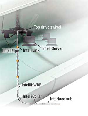 |
Fig. 1. The telemetry drill pipe is composed of five main components. MWD/LWD and rotary steerable system (RSS) tools, InSite IXO sub, telemetry pipe, IntelliLinks and top drive swivel.
|
|
1. MWD/LWD and RSS tools
2. InSite IXO sub connecting Grant-Prideco’s telemetry pipe with MWD/LWD and RSS tools for high-speed, bi-directional communication of logs and commands to and from the surface
3. Telemetry pipe for data transmission
4. IntelliLinks to boost transmission signals and to take measurements at their positions in a wellbore
5. Top drive swivel for data extraction to a surface repository, while the drill pipe rotates.
MECHANICAL-ELECTRICAL INTERFACE
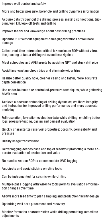
The IXO sub is the mechanical-electrical interface between the tools and network. Currently both 4-in. and 5-in. versions are available. Use of the network enables bi-directional communication between the surface and the downhole tools with speeds of 1 Mbps under development. Greater communication speed leads to many specific advantages, Table 1. Among these are optimized drilling, imaging-while-drilling and seismic while drilling.
| TABLE 1. Technology advantages |
 |
|
High-speed data from drilling optimization sensors, including distributed sensors along the drillstring, such as pressure-while-drilling and drillstring dynamics management can provide a new understanding of the drilling process, while producing increased safety and operational efficiency. This yields better simulators, improving modeling accuracy before, during and after drilling.
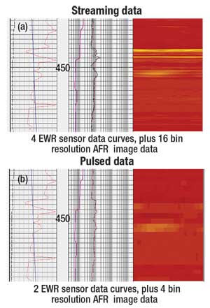 |
Fig. 2. This example shows the resolution difference between (a) streaming data using telemetry pipe and (b) traditional mud pulse data transmission.
|
|
Detailed high resolution images from resistivity sensors, as well as density and acoustic sensors, can refine understanding of the geological structure. Accessing all the measurements from deep reading, multiple-depth-of-investigation devices provides the data necessary to make decisions about trajectory changes in real time. Fluid mobility, borehole breakout, loss zones, shale reactivity, fracture propagation and any other time-related changes in wellbore conditions can be monitored and studied, and treatment remedies can be objectively assessed.
The interface delivers telemetry speeds necessary for seismic-while-drilling, while velocity checkshots reduce seismic model error to improve wellbore positioning. Seismic data acquired ahead of the bit can reveal potential pressure hazards, allowing an operator to avoid dangerous rig safety situations.
DRILL PIPE
The telemetry pipe stands transmit data from one end to the other end of the pipe by way of a set of patented inductive coils that are connected to a high strength, high-speed steel cable, Fig. 3. The cable is connected to the coils through a small conduit inside the pipe connection. The cable is stretched between the two drill pipe joints, anchored at the joints and stretched along the tubular.
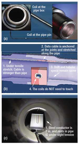 |
Fig. 3. Telemetry pipe stands transmits data from one end to the other of the (a) pipe by way of a set of (b) patented inductive coils that are connected to a (c) high strength, high-speed steel cable. The cable is connected to the coils through a small conduit inside the pipe connection, note mirror reflection.
|
|
The drilling tubular is not affected by the addition of the telemetry system. Its mechanical characteristics and integrity remain the same. High transmission reliability is achieved because the inductors do not need to touch each other. Therefore, standard pipe connection procedures and materials such as pipe dope etc. can still be used.
LINKAGES
An intelligent drillstring can make measurements at nodes along the string, Fig. 4. The nodes allow operators to acquire, compare and model different measurements, as a well is drilled. This information is useful in evaluating mechanical and wellbore conditions that can decrease ROP or increase the possibility of drill pipe failure.
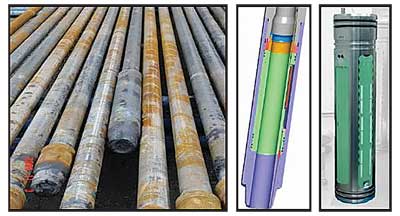 |
Fig. 4. IntelliLinks (left) and exploded view of individual links showing cavities designed to hold measurement instruments and signal boosters. The measurement nodes contain signal processors that acquire and process data, and boost signals to and from the surface. They are transparent to the drilling operation.
|
|
The nodes contain signal processors that acquire data, process data and boost signals to and from the surface. They are transparent to the drilling operation, since they only appear as a longer bottom connection in a tubular. The tubulars ID and OD remain unchanged.
TOP DRIVE SWIVEL
The top drive swivel allows the drill pipe to rotate while maintaining communication with recording, analysis and control devices at the surface, Fig. 5. The line leading off to the right from the “cake-tin” near the top of the visible pipe connects to the recording, analysis and control devices.
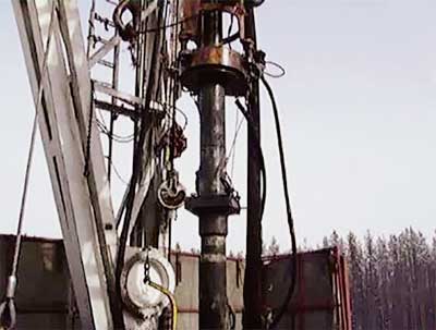 |
Fig. 5. The top drive swivel allows the telemetry pipe to rotate while maintaining communication with surface recording, analysis, and control devices.
|
|
FIELD EXPERIENCES
The system has been used successfully in the US, Canada, Mexico, northern Europe and Asia. In the US, the system showed the capability of detecting and correcting a malfunction in an MWD tool without having to trip out of the hole. The time-savings was significant in terms of rig operating costs.
The US experience also put acquisition and dynamics analysis to good use. Undesirable jar cocking and activation was detected and eliminated by changing the drilling parameters. More such real-time information can lead to smoother, more efficient drilling.
In northern Europe the system led to smoother, more efficient drilling. It provided much better control of the drillbit’s path. The operator used the technology while drilling complex, multilateral wells. With data reported almost immediately to surface, the need to play “catch-up” to bring a well path back on plan was avoided.
The Asian experience could be called “daring.” The operator concluded that the prospect could be drilled safely only with a closed circulation and pressure management system that would monitor and maintain constant bottom hole pressure while drilling and during connection. The system would have to detect kicks as early as possible, respond immediately to downhole pressure changes, and simultaneously circulate out gas from any kicks.
In their search, the operator learned that no one system could provide all those capabilities. However, they also learned that a combination of specific technologies could handle the challenge. The combination of IntelliServ features along with appropriate at-bit measurement tools and with a crossover-sub to unite measurements with a communications line did the trick. 
TECHNICAL DETAILS
At the present time, data sensors are set to transmit every four seconds, but with pressure-while-drilling data transmitted every second. By the end of 2007, both pressure data and vibrations information will be transmitted ten times per second. Presently, image transfer takes place at 0.32 kbps. By the end of 2007, full GeoTap and uncompressed image data from all azimuthal sensors will be operational.
|
InSite IXO Specifications
|
|
| IXO6 tool OD, in/mm |
6.75/171 |
| Hole size, in./mm |
8 3/8 to 9 7/8/213 to 251 |
| Length, ft/m |
9.8/3.93 |
| Max temp, °F/°C |
302/150 |
| Max pressure, psi/bar |
18,000/1,241;
25,000/1,724 |
| Memory, Gb |
1 |
| Measurement type |
Telemetry rate |
| Operation frequencies |
56,000 bps; 1 Mbps
(testing) |
| |
|
Interface dimensions
|
|
Nominal tool OD
|
6¾ in./171 mm |
| Hole size range |
8 3/8 -9 7/8 in./ 213-251 mm |
| Length |
9.8 ft/3 m |
| Max OD |
7.36 in./187 mm |
| Collar ID |
1.90 in./48 mm |
| Top connection |
Grant Prideco
DS50 box |
| Make up torque, top |
30,100-43,900 ft-lbs
40.8 to 59.5 kN-m |
| Bottom connection |
NC50 (4-1/2 IF) pin |
| Make up torque-bottom |
30,000-33,000 ft-lbs
40.6-44.7 kN-m |
| Max dogleg severity |
|
| Rotating |
10°/100 ft/
10°/30 m |
| Sliding |
21°/100 ft/
21°/30 m |
| Max bit weight |
100,000 lbs/
45.36 m-ton |
| Max operating temperature |
302°F/150°C |
| Max survival temperature |
329°F/165°C |
| Max operating pressure |
18,000 psi |
| High pressure option |
25,000 psi |
| Max mass flow rate |
10,000 lbs/min./
4,536 kg/min. |
| Max sand content |
2% |
| Max rotary speed |
180 rpm |
| Lateral vibration |
10 min. at 90g
(peak shock) |
| Axial vibration |
10 min. at 40g
(peak shock) |
| Memory size |
1 Gbe |
Battery capacity
|
200 hr |
|
THE AUTHORS
|
|
Reginaldo Rodriguez has 22 years of experience, five years in the Pemex’s Petrophysics department and 17 years in the Drilling department. Rodriquez is presently the drilling superintendent, Design and Drilling, in charge of the Bellota-Jujo and Macuspana assets in the South Region operation unit for Pemex Exploration and Production.
|
|
|
Maximo Hernandez earned a BS degree in electronic systems engineering and MS degree in petroleum engineering and project management. With 15 years in the drilling industry, he has held positions in operations and management of wireline, directional drilling and drill bit operations in seven countries, including worldwide responsibilities for the design, development and commercialization of real-time drilling engineering and drilling optimization products for a major service company. Hernandez is presently the business development manager for IntelliServ.
|
|
|
Paul Hamel earned a BS degree in business and has eight years industry experience. He has held positions in product management for integrating drilling technologies with production surveillance and engineering applications, led a production optimization consulting group in Asia Pacific and presently champions InSite IXO for Sperry Drilling Services.
|
.
|


