SPECIAL FOCUS: DRILLING REPORT
Large hole RSS used for shallow kick-off, directional control in soft sediment
The first kick-off with a rotary steerable system in a 26-in. hole successfully built angle in soft Gulf of Mexico sediment, in a deepwater well.
Mark Drummond and Karlin Costa, BP; Doug Renfrow, Quadril Energy LP; Riaz Israel, Osman Maung, Goke Akinniranye and Ravikumar Peddibhotla, Schlumberger
Rotary Steerable Systems (RSS) have revolutionized the way that oilfield operators drill wells. The advantages of drilling with this technology are documented and have been proven in a wide variety of drilling applications. Utilizing a rotary steerable system allows E&P companies to push the drilling envelope by providing access to more complex plays. The efficiency and reliability of the system also contributes to an overall reduction in lifting costs.1 The advantages of using RSS are highlighted in Fig. 1.1
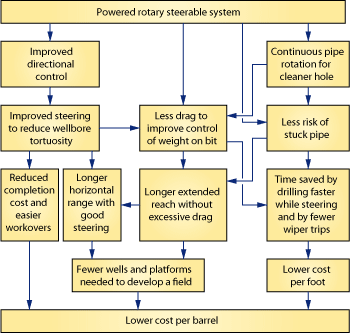 |
Fig. 1. Advantages of using rotary steerable systems.
|
|
The need to access deeper reservoirs, high step-out targets and large-bore well construction requirements for HPHT and high-flowrate deepwater wells demanded that the advantages that RSS technology brought to smaller hole sizes be delivered to large hole sizes.
This need drove BP to collaborate with the directional service provider to deploy their push-to-bit RSS in a 26-in. directional drilling application. The 26-inch RSS had been used successfully in vertical drilling applications. In the past, the largest hole size that used RSS for directional work was 18¼ in.2 Larger hole sizes had been drilled using the 18¼-in. RSS with various hole-opening devices some distance behind the RSS tool. While this method does have its applications and operational efficiencies, it was not considered to be optimally suited to the situation discussed here for the following reasons:
- Too large an incremental hole size increase from pilot bit to reamed hole size (i.e., 18¼ in. to 26 in.).
- RSS plus hole opener at these hole sizes would impact the BHA’s directional capability.
The RSS system considered for this hole size had already been developed and commercialized by the directional service provider, although all previous applications had been limited to vertical drilling.3
DIRECTIONAL CHALLENGES IN SOFT SEDIMENTS
Having realized the substantial benefit of RSS on many previous campaigns, BP was keen to deploy this technology in larger hole sizes, and thus extend the benefits from top to bottom of planned wells.
The system was put to the test as part of a Gulf of Mexico (GOM) field development set in almost 7,000 ft of water. The reservoir to be accessed stepped out 1.4 mi from the template at a depth of less than 9,000 ft below the mudline. This effectively translated into a displacement-to-TVD ratio of about 0.78, placing it within the industry-accepted envelope of ERD. To intercept this reservoir, at an inclination that conformed to the drilling basis of design, required deviation from vertical within 300 ft of the mudline. Well construction and delivery requirements called for 26-in. hole at these depths. The typical trajectory for the wells discussed in this article is in Fig. 2.
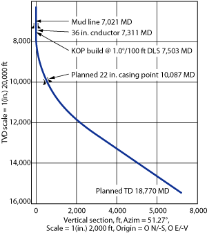 |
Fig. 2. Typical well trajectory.
|
|
BP’s prior attempts at drilling large, shallow deviated wellbores in deep water had proven highly challenging. Conventional Positive Displacement Motors (PDMs) were used, and their limitations were evident. Performance summaries of these wells are discussed below.
Well AA-2. High levels of stick-slip were observed. The inability to mitigate this severe stick-slip, along with insufficient rpm to properly clean the hole, resulted in the assembly twisting off, resulting in an expensive deepwater fishing job. The fishing job was unsuccessful, and a two-day sidetrack operation was required to recover the well. The ability to increase surface rpm is key to mitigating the stick-slip vibration mode. Drilling with a PDM limits the surface rpm to between 40 and 60, due to fatigue considerations resulting from the bent housing setting. This rpm restriction can also impact hole cleaning while drilling. Surface rpm >80 has been proven to be beneficial for effective hole cleaning. An example of the BHA used to drill these wells is in Fig. 3.
 |
Fig. 3. 24-in. PDM BHA used for earlier directional wells.
|
|
Well AB-3. Drilled with a PDM, this well suffered from lower-than-expected overall ROP, due to significantly reduced ROP while slide drilling through a tough formation. This formation’s natural tendency pushed the assembly away from the intended direction. Thus, a high percentage of time was spent slide drilling to ensure that the directional objectives were achieved. As with well AA-2, high levels of stick-slip were prevalent throughout the run, thus contributing to further reduction in ROP.
Overall ROP for this section was 30% less than the average of other 24-in. sections drilled in the field during 2006. Figure 4 compares the ROP of four wells drilled in this field in 2006 with identical PDMs. Note the overall reduction in ROP for the wells discussed, AA-2 and AB-3 (both directional), when compared to the two remaining wells (both vertical). This reduction in ROP is attributable to both the reduced ROP while slide drilling, as well as the less efficient use of the input drilling energy in the system, as more of this energy is dissipated through shock and vibration. Average length of these sections was 4,300 ft; the reduction in ROP was 30ft/hr. This represented almost two days of additional drilling time, when a PDM is used to drill a directional interval.
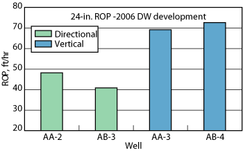 |
Fig. 4. Field ROP comparison: Vertical vs. directional wells.
|
|
The challenges of shallow directional work in deep water do not end with drilling. Once the wellbore is drilled, high-volume, high-risk cement jobs always follow. A good cement job is critical at this stage, since this string typically provides the axial support for the wellhead, BOPs and ancillary subsurface components. A poor cement bond, or channeling during or after the cement job, may also result in insufficient isolation of shallow hazards. This could potentially require drilling a new wellbore.
Drilling these shallow directional sections often results in an over-gauged hole, introduced via interaction of the drilling fluid (typically gelled seawater in riserless applications) with the formation. The degree of washout is theorized to be directly related to the length of time the formation is exposed to seawater drilling fluids. Low ROP slide drilling, time spent orienting to slide, plus non-optimized drilling impacting on ROP, all effectively contribute to over-gauged hole. Calipers obtained by measuring the circulating time of a marker fluid (often referred to as “fluid calipers”) on prior wells have indicated that these wellbores may grow from 24-in. or 26-in. drilled diameter to a 34-in. final diameter.
In directional hole, centralization of the casing is essential for a good cement job. Large washouts can be detrimental to providing a good cement job. Fluids will tend to have higher annular flowrates on the wide side of the annulus, making fluid displacement (mud removal) difficult on the low side of the casing. Additionally, the larger the hole size for a given fluid pump rate, the lower the annular velocity of the fluids being pumped, again impeding mud removal and impacting cement job quality. Cement stimulation models for these wells indicated an improved cement coverage for a 28-in. hole (2-in. overgauge) when compared to a 34-in. hole (8-in. overgauge), Fig. 5.
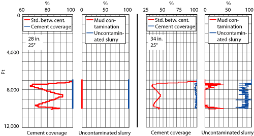 |
Fig. 5. Cement stimulation models indicated an improved cement coverage for a 28-in. hole (2-in. overgauge, left panels) compared to a 34-in. hole (8-in. overgauge, right panels).
|
|
THE WAY FORWARD
Having developed a thorough understanding of the challenges of shallow directional drilling in deep water, and given the requirements for the wells discussed in this article, it became critical for BP to improve on the performance of similar past wells. RSSs were seen as the most appropriate solution. The benefits of 100% rotation while drilling at high RPM’s has been demonstrated on countless wells. The idea behind introducing this technology was to improve the overall drilling efficiency. This would relate to faster penetration rates, less washout and better control of downhole shocks, vibration and torque. This, in turn, would lay the foundation for a better cement job and positively impact the well’s overall success.
While the potential benefits that RSS could bring to this project were clear, there was some uncertainty surrounding the ability of the existing 26-in. tool to effectively steer and maintain control in soft sediments. BP and the service provider then entered into a massive technical and logistical planning effort to ensure the success of what would prove to be the world’s first use of an RSS in a 26-in. directional drilling application.
PLANNING FOR SUCCESS
A pre-job analysis was conducted to determine the compressive strengths of the shallow sediments. A Mechanical Earth Model, or MEM (a mathematical representation of the in-situ stresses, rock properties and pore pressure as a function of depth for a particular stratigraphic area), was developed for a typical well in this location. The model was populated with rock physical attributes, such as compressional and shear velocity, density, effective and total porosity, and volume of clay acquired through logging-while-drilling and wireline formation evaluation measurements. This information was used to determine the Unconfined Compressive Strength (UCS) for the formations to be encountered down to a depth of 2,400 ft below the mudline. The UCS was then compared against the actual force that the RSS pads would exert on the formation over the full range of expected flowrates. A proprietary, experimental correlation used to relate formation strength and pad force to build rate potential was established by the service company. It was used to estimate what range of build rates could reasonably be expected under the existing conditions.
The MEM results and subsequent analysis demonstrated that the 26-in. push-the-bit rotary steerable tool would be able to build at least 1.0°/100 ft across this interval.
The RSS performance in a 26-in. borehole was to be evaluated over a two-well program. The well trajectories were planned to kick off within 300 ft below the mudline and designed with the recommended build rate of 1.0°/100 ft. The BHA design incorporated a flex joint to improve dogleg capability. Figure 6 illustrates the planned, 26-in. RSS BHA.
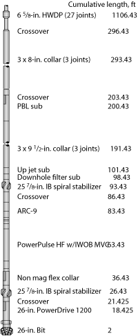 |
Fig. 6. Rotary steerable BHA for drilling 26-in. section.
|
|
The MWD tool was run below the LWD to provide real-time, continuous directional and inclination measurements closer to the bit. These measurements would be transmitted to the surface at 6-in. intervals. This allowed the directional team to have earlier evaluation of the BHA tendency and the opportunity to respond earlier to undesired directional tendencies. A mill tooth bit (IADC code 115) was selected, due to the expected formations. Seawater was used as the drilling fluid.
Objectives of the runs were clearly defined:
- Kick-off and drill a riserless, 26-in. directional hole according to the required trajectory.
- Minimize borehole washout for a successful 22-in. casing run and subsequent cement job.
MEETING THE CHALLENGE
In Well 1, the trajectory called for kicking off 50 ft below the 36-in. conductor and building at 1.0°/100 ft to an inclination of 25.8° at section TD. The ROP for the first few stands drilled ranged from 360 to 540 ft/hr. Early surveys showed the RSS tool to be building angle at 0.3 to 0.6° on each survey, with a total dogleg output of 0.4° to 0.7°/100 ft. With about 3° of angle in the hole, a switch to a gravity toolface was made, and the well lined up the desired azimuth. Multiple settings were then used to keep the well on the desired trajectory, on the way to the planned casing point. Figure 7 presents a plot of continuous inclination vs. depth. The final survey showed 22.5° of inclination. Shock and vibration issues were non-existent. The well was successfully cased and cemented.
 |
Fig. 7. Continuous inclination measurement from the first 26-in. RSS directional run.
|
|
Well 2. The trajectory called for kicking off 100 ft below the 36-in. conductor and building at 1.0°/100 ft to an inclination of 25.8° at section TD. The lessons learned from the previous run were incorporated into this run, with BHA design and kick-off procedures adjusted slightly. As seen in the first run, ROP slowed after the first few stands, as more competent formation was encountered. Overall ROP on this section was ~170 ft/hr, compared to 115 ft/hr on the previous run. This was attributed to the improved practices implemented. The final survey showed 24.5° inclination. As on the first well, shocks and vibrations were non-issues while drilling. The well was successfully cased and cemented.
CONCLUSIONS
On the previous shallow directional wells drilled by BP in the area, typical ROP averaged 50 ft/hr, while vertical wells’ ROP averaged 70 ft/hr. On-bottom drilling time for the two 26-in. sections done with the RSS proved to be 23.4 hr for a 2,706-ft interval on Well 1 and 15.9 hr for a 2,696-ft interval on Well 2. This gave an average ROP of 137 ft/hr for wells drilled with the 26-in. RSS. A 2,700-ft directional section drilled at the PDM ROP would require 54 hr. The 26-in. RSS has been able to deliver an average time savings of 34 hr, representing a 63% reduction in drilling time. Figure 8 illustrates the comparison between PDM and RSS for large-hole, shallow directional work in deep water.
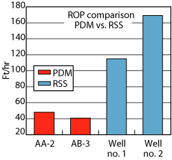 |
Fig. 8. ROP comparison in large directional hole PDM vs. RSS.
|
|
Average hole diameter (as determined by fluid caliper) for these two sections was 31 in., a 10% reduction in hole washout. The reduced washout is attributable to less time that the wellbore was exposed to seawater before cementing.
Based on pre-drill objectives for the run, the 26-in. RSS has delivered measurable evidence that met the objectives of improvement of ROP and reduction in hole washout. The results of these runs clearly demonstrate that the benefits of RSS can be translated to large hole sizes drilled directionally in deepwater environments. Introduction of this technology reduced the overall time spent drilling these directional sections by increasing ROP, eliminating the need for slide drilling, and generally optimizing the drilling process by reducing unwanted downhole shocks and vibrations. The benefits of 100% rotation while drilling lead to improved hole conditions, including, less washout, from the reduced exposure time to seawater, and lower doglegs. Both of these factors improve the ability to run casing and obtain an adequate cement job.
The applications for a 26-in. RSS for shallow directional work in deep water are not limited to those discussed in this article. Deepwater operators and service providers are identifying other opportunities for improving drilling in directional work in shallow salt bodies, near-bit inclination measurements for anti-collision mitigation when exiting multiple-well templates, and pushing bigger hole deeper, as required in many HPHT well construction designs. 
ACKNOWLEDGMENTS
The authors thank the following contributors: Karlin Costa, drilling superintendent, BP GOM Deepwater; Mark Drummond, drilling engineer, BP GOM Deepwater; Doug Renfrow, drilling engineer, BP GOM Deepwater; Aaron Dondale, district technical engineer, Schlumberger Well Services; Zsolt Nagy, senior geomechanics engineer, Schlumberger Data & Consulting Services and Aron Kramer, LWD Petrophysics, Schlumberger Drilling and Measurements.
This article is derived from AADE paper 07-NTCE-06, presented at the 2007 AADE National Technical Conference and Exhibition, Wyndham Greenspoint Hotel, Houston, April 10-12, 2007.
LITERATURE CITED
1 P. Copercini, F. Solomon, M. El Gamal and I. McCourt, “Powering up to drill down,” Oilfield Review Vol. 8, No.1, pp. 4-9, Winter 2004.
2 J. Pinzon, C. Prusiecki and S. Barton, “First GOM deepwater well deploying an integrated rotary steerable drilling system drills 18-1/4-inch section,” AADE paper 03-NTCE-43, AADE National Technical Conference, Houston, April 1-3, 2003.
3 G. Brusco, P. Lewis and M. Williams, M., “Drilling straight down,” Oilfield Review Vol. 8, No.1, pp. 14-17, Autumn 2004.
|
THE AUTHORS
|
|
Mark Drummond is a drilling engineer at BP, assigned to deepwater Gulf of Mexico production projects. He has more than 20 years of experience working in the E&P industry and has been working on Gulf of Mexico projects since joining BP in 1994. Mr. Drummond holds BS and masters degrees in petroleum engineering from Texas A&M University.
|
|
| |
Karlin Costa is an operation superintendent for BP, Egypt. Previously, he was a Wells Team leader for the Gulf of Mexico Deepwater Exploration Business Unit. Costa has been with BP for nine years in a variety of assignments in Deepwater Gulf of Mexico, and Egypt. Prior to joining BP, Costa was with Conoco, working in Nigeria, Russia and Indonesia. He is a graduate of Montana Tech University.
|
|
| |
Doug Renfrow is a principal of Quadril Energy LP and is consulting with BP in the deepwater Gulf of Mexico. He has more than 30 years of experience in various offshore areas around the world. Mr. Renfrow earned a BS degree in mechanical engineering for the University of Missouri at Rolla.
|
|
| |
Riaz Israel is a senior drilling engineer for Schlumberger in Houston, supporting BP GOM deepwater operations, a position he assumed in July 2006. Prior to this, he served as a drilling engineer based in Trinidad, where he joined Schlumberger in 2001. Mr. Israel is a member of SPE and holds a master of engineering in petroleum engineering from the University of the West Indies, St. Augustine, Trinidad.
|
|
| |
Osman Maung is the directional drilling coordinator for Schlumberger in Deepwater Exploration, Development and Tuscaloosa Land group. He also worked in M/LWD and directional drilling, as well as the BP Thunder Horse project as senior drilling engineer. Mr. Maung joined Schlumberger in 1990 as a field engineer for mud logging. He earned a BS degree in industrial technology from the University of Louisiana at Lafayette.
|
|
| |
Goke Akinniranye is the drilling engineering manager for Schlumberger North and South America in Houston. He joined Schlumberger in 1986 as a field engineer and has more than 20 years of oil and gas experience. Mr. Akinniranye has served as field service manager, senior instructor, technical manager and InTouch engineer. He earned a BS degree in geophysics/geology from the University of Ife, Nigeria, in 1985. He is a member of SPE, AADE and IADD.
|
|
| |
Ravi Peddibhotla is the technical sales engineer supporting BP in Houston for Schlumberger since August 2005. He previously supported operations in India as a field services manager for four years. Mr. Peddibhotla joined Schlumberger as a field engineer in 1996 and worked as an MWD-LWD engineer in the Middle East. He holds a BS degree in petrochemical engineering from the University of Pune, India.
|
|
|


