ARTIFICIAL LIFT
What’s new in artificial lift
Part 2�Ten companies offer 13 improvements in electric submersible pumping and other artificial lift operations.
James F. Lea, Mewbourne School of Petroleum and Geological Engineering, Oklahoma University; Herald W. Winkler, Texas Tech University; and Robert E. Snyder, Consultant
Part 1, presented last month, covered three categories of artificial lift technology: Sucker Rod and Progressing Cavity Pumping (PCP), and Miscellaneous: Gas lift/Deliquefying/Jet pumping.
This concluding article introduces and updates developments in other categories of artificial lift. Four of the presentations include new downhole and surface equipment for ESP systems. The remaining nine items cover miscellaneous contributions for new downhole pumps, operations monitoring/control, related downhole equipment and gas lift.
ELECTRIC SUBMERSIBLE PUMPS (ESPs)
Described here are four new systems for: an improved ESP installation system; an advanced motor protector; Schlumberger’s organization involving a joint team to study ESP performance; and a new module to minimize effects of ESP power interruptions.
Improved ESP installation. A new REDA* Maximus* electrical submersible pump system from Schlumberger addresses the unique needs of installations in extreme weather operations. The system significantly reduces wellsite procedures and risk of failure due to human error or inclement weather. It further mitigates early-run failures of conventional ESPs by providing fully integrated or plug-and-play sensor, motor and protector components.
Components are shipped to the wellsite filled with oil, with an oil compensation shipping cap allowing for thermal expansion or contraction. The components maintain oil capacity without trapping air bubbles, therefore reducing the need to be serviced at the wellsite. During installation, this shipping cap is removed and the protector and motor are joined, as shown in Fig. 1, with the oil fill draining out.
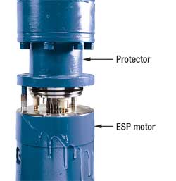 |
Fig. 1. ESP protector and motor during wellsite assembly after the shipping cap is removed from the protector. Note protective oil draining out.
|
|
Many of the wellsite tasks have been moved to the controlled environment of the manufacturing or service center, further reducing human error risk. Oil servicing during assembly, coupling placement and certain shimming procedures are conducted at the service center and allow for a simple, timely ESP installation. This system has not only improved wellsite assembly reliability, and mitigated impact of weather conditions, but it also saves costly rig time and improves ESP reliability.
ESP motor protector. Schlumberger has available the REDA Hotline* 550 advanced motor protector system, specially designed to handle challenging environments. Available in different configurations, it provides a fit-for-purpose solution for high-temperature steam-assisted gravity drainage (SAGD) installations, as well as sand and solids production, high-gas-cut wells and corrosive fluids. The advanced motor protector (AMP) design features an optional Inconel* metal bellows that replaces the elastomeric bag, Fig. 2.
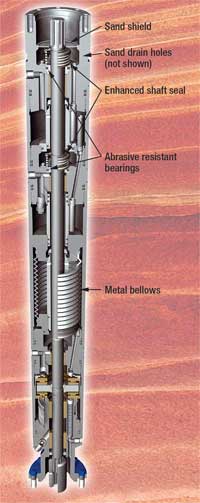 |
Fig. 2. Advanced motor protector system with metal bellow expansion chamber.
|
|
|
Using metal bellows extends operation temperature to 550°F, in current configurations, far beyond that of the elastomeric-bag protector. The AMP was a critical aspect of the high-temperature ESP, giving a SAGD installation life of 1,043 days and still running.
In addition, the AMP system has proven to be effective in gassy wells, as the metal bellows prevents gas from migrating and displacing the motor oil. The metal bellows is resistant to H2S, and impermeable to gas, and thus is more suitable for high well temperature and H2S.
The Hotline 550 advanced protector design also incorporates a novel protector head design with an elevated shaft seal, sand shield and sand drain holes. Thus, any sand or solids that enter the protector top will be diverted to the wellbore.
ESP Lifting Service. Offered and operated by Schlumberger, the Advanced ESP Lifting Service is a real-time, solution-focused workflow for surveillance, diagnostics and optimization of ESP wells. It is a web-hosted, end-to-end, monitoring and surveillance system that integrates data gathering and transmission (SCADA) with production optimization and diagnostic services. The Advanced ESP Lifting Service (ALS) combines the latest technology in downhole ESP sensors and motor controllers with artificial lift and reservoir engineering to provide 24/7 ESP surveillance, diagnostics and optimization candidate identification.
See the technical article on page 69 for more details.
Power Ride Through Module. Power interruptions are a serious issue for both downhole ESP systems and the surface variable speed drives (VSD) used to control the overall system. And a new technology from Baker Hughes Centrilift, Claremore, Oklahoma, the Centrilift Power Ride Through Module, allows the VSD to detect power interruptions and energize the downhole equipment during these events.
For years the philosophy behind VSD design was to protect the downhole equipment by shutting down the VSD when it is subjected to power transients. However, the well downtime associated with this approach negatively impacted overall production capabilities and shortened ESP life due to voltage transients and restarts.
The new Power Ride Through Module (PRT) eliminates the impact of power interruptions of less than half a second, which account for most of all power transient events. The patent-pending technology includes both a software algorithm and an energy storage device. The algorithm detects and decouples/couples the power grid from the VSD during a power sag; and the energy storage unit keeps the downhole motor energized during these short-term events.
The software also keeps a record of the length of the power transient and when the event occurred. The PRT software is integral to every new Centrilift GCS Electrospeed* 3 VSD, Fig. 3, and the power storage module and software can be added to any existing GCS Electrospeed II.
 |
Fig. 3. The Power Ride Through system helped sustain ESP system operation during a power outage. With power restored, the VSD synchronized to incoming power supply and restored the ESP system to normal operation.
|
|
A Venezuelan operator suffered numerous field shutdowns due to power interruptions, of which 90% lasted less than half a second. During field tests, the PRT system reduced VSD shutdowns due to power system transients by 85% in this field, and the operator plans a full-field installation that targets a 5% production increase.
Other new ESP technologies from Centrilift are aimed at providing boost capabilities for high-flow subsea wells in deepwater applications and long step-outs. ESP technology has been leveraged for several seabed system designs, including: vertical booster stations, horizontal booster stations, ESP Jumper* systems and riser lift systems.
MISCELLANEOUS
Nine items in this category include: a shallow-well hydraulic gas pump; high-pressure offshore well gas lift; a cementing system for monobore wells; wireless tank level monitoring; measuring instruments for hazardous areas; field well motor controllers; a new pulse pump for gas well deliquefying; an H2O/CO2 WAG injection controller; and precision electrometric PCP rotor coating.
Hydraulic gas pump. A new pumping system from Weatherford International Ltd. is proving ideal on shallow wells using steam-assisted gravity drainage (SAGD) production in the heavy-oil fields of Canada. The Hydraulic Gas Pump (HGP) is a positive-displacement pump that uses pipeline gas pressure as the pump piston in its operation. Gas is used to displace the liquid to surface, and it is then vented to the annulus, where it is collected and used for steam generation, Fig. 4. None of the gas is consumed by the pump.
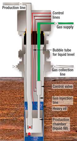 |
Fig. 4. The hydraulic gas pump uses high-pressure surface gas through a separate tubing string to a downhole chamber, where heavy oil is displaced to surface through the production line. Control lines open/close the gas supply line. Operational control modes include by timer or by liquid level above the production chamber.
|
|
Typical gas pipeline pressure in Northern Alberta, Canada, is about 5,500 to 6,000 kPa (800 to 870 psi), which proves sufficient to pump wells at 500 to 550 m (1,640 to 1,804 ft) total vertical depth (TVD) and up to rates of 700 m3/d (4,400 bpd). Slow cycle rates, few moving parts and 100% turndown are just a few of the key features of the HGP.
The company has a number of initiatives underway for enhancing the system and expanding its applications. One objective is a higher-temperature HGP capable of withstanding 330°C (626°F) temperatures for use in cyclic-steam heavy-oil recovery operations.
High-pressure gas lift. As developed by Schlumberger, the XLift* high-pressure gas lift system allows for completion in deepwater, extended-reach, subsea and highly deviated gas lift wells. The retrievable XLift XLI* valve has a patented, edge-welded pressure balanced bellows system, Fig. 5. This assembly reduces the required internal gas charge, while increasing operating injection pressure.
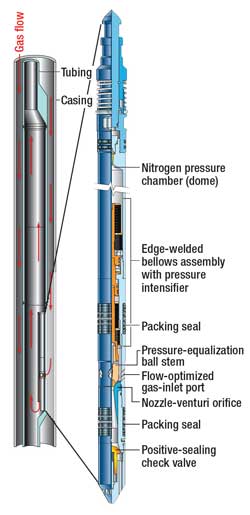 |
Fig. 5. High-pressure gas lift valve system.
|
|
|
With operating injection pressure ranges of 2,000 to 5,000 psi at depth, and high injection rate capabilities, the system significantly extends the reach of gas lift wells and provides extended well and field life. The higher injection pressures and deeper injection points allow wells to be completed with fewer mandrels and valves, as well as allowing for higher drawdowns and increased production.
The XLift XLI* gas valve is entirely subsurface-controlled with no physical linkage to the surface. A patented, field proven, venturi flow configuration offers more efficient and stable gas throughput for higher performance in deep-lift applications. The unique 1¾-in. OD improves the valve’s operating characteristics, allowing for higher volumes of injection gas, improving the potential for high-volume wells; and it further reduces well intervention risk.
For details, see the technical article in World Oil, April 2007, page 95.
Cementing system for monobore wells. When evaluating cost vs. return on marginally productive, short-life wells, it all comes down to minimizing cost while maximizing return. That is why “disposable” wells, i.e., those with life expectancies of three to five years, are becoming increasingly common.
Cemented monobore wells offer operators the most economically viable method of completing these short-life wells but, until now, the cement-through completion process precluded use of packers of positive seals. Additionally, because standard gas lift devices do not permit cement-through operations, cemented monobore wells have had no proven method for artificial lift as production decreased.
Baker Oil Tools’ Mono-Trip CemenThru* Completion System was developed to add artificial lift capability, improved safety and unmatched efficiency to cemented monobore wells. The system’s components, specifically designed for cement-through applications, include the patented CemenThru* Side Pocket Mandrel (SPM), the Cement Safe* Tubing Retrievable Surface Controlled Subsurface Safety Valve (TRSSV), and the HP Defender* Hydrostatic Closed Circulating Valve (HCCV), as well as a hydraulically set ZXP* liner top packer and an extended wiper plug, Fig. 6.
 |
Fig. 6. The Mono-Trip CemenThru system combines CementSafe TRSV with CemenThru SPM in a one-trip completion. SPM and TRSV are made up as integral parts of production tubing when preparing for gas lift, chemical injection, waterflood or other special applications.
|
|
Typically, components like safety valves and gas lift mandrels do not perform well when cement is pumped through the tubing and up the annulus. But with the cement-tolerant components, the Mono-Trip System (MTS) can be used to complete cemented monobore wells with safe and efficient gas lift systems in place. And with the MTS, what used to take up to three trips has been reduced to one.
Chevron has recognized Baker Oil Tools for successful completion of its 100th Mono-Trip CemenThru* completion in the Gulf of Thailand.
Wireless monitoring technology. Ferguson Beauregard, Tyler, Texas, offers the latest wireless monitoring technology with its iNodes* family of products. The Tank Level Monitor 3 (TLM3), Fig. 7, is a reliable, accurate float-based level sensing technology designed for one or two product tanks, and has low power consumption with its solar-powered, rechargeable battery. The small package includes power supply, data storage, processing and communications.
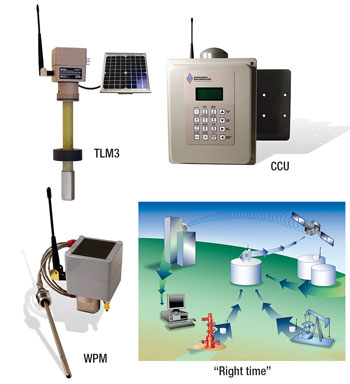 |
Fig. 7. The iNodes family of products includes: 1) Tank Level Monitor 3 (TLM3) wireless float-based level sensor for one or two tanks; 2) Wireless Pressure Monitor (WPM) wellhead pressure measurement with optional temperature probe; 3) Concentration & Communications Unit (CCU) collects remotely monitored data and delivers to user through Internet; and 4) “Right Time Data” on-demand access to remote data, as from plunger lift or pumping wells, which allows strategic planning of daily operations and rapid problem response.
|
|
Field configuration, software upgrade and local data retrieval are accomplished using any iMonitoring Compact Flash Radio-enabled (CFR) personal computer, including laptop PCs and PDAs. The user-configurable alarm detection/notification system features a drop alarm that notifies the customer if oil is thieved during non-production times. The system also features alarm notification via telephone or email, and an alarm holdoff feature that prevents costly, multiple, same-alarm notifications.
The Wireless Pressure Monitor (WPM), Fig. 7, is designed for wellhead pressure measurement. It allows remotely monitored data to be collected/delivered over the Internet or viewed onsite using a CFR-enabled PC or PDA. Like the TLM3, the WPM is solar-powered with a rechargeable battery, and its small package includes power supply, data storage, processing and communications. Its user-configurable pressure/temperature alarms allow notification via telephone or e-mail, while its alarm holdoff prevents costly multiple alarm notifications.
The Modbus Gateway Concentration & Communications Unit (CCU), Fig.7, is an iNodes CCU designed to support the Modbus protocol in a Supervisory Control and Data Acquisition (SCADA) system. The MG-CCU interfaces with an industry-standard remote terminal unit (RTU), or long-range radio, allowing the SCADA infrastructure to retrieve data from any remote iNodes sensor. Right Time Data from sensors is mapped to Modbus registers, allowing locally collected data to be downloaded to a desktop PC through Microsoft ActiveSync, or by reading the PDA or laptop removable memory card. Field configuration, software upgrades and local data retrieval are accomplished by any iMonitoring CFR-enabled PC, including laptop PCs and PDAs, Fig. 7.
Instruments for hazardous areas. Echometer Company, Wichita Falls, Texas, has developed a line of instruments that, when properly installed and used, are certified to be safe for taking measurements in areas where explosive atmospheres are present, and are classified as Class 1 Division 1, Group A, B, C & D, T4 hazardous areas. These areas include wellheads of flowing and artificially lifted wells, and the vicinity of BOP stacks in drilling wells, as classified in API Recommended Practice 500.
Safety in the workplace is a major consideration for selecting and applying instruments in conjunction with oil/gas operations.
In response to recent development of safety guidelines/requirements, the following specially modified equipment has been certified to be safe for operation in explosive atmospheres: 1) Compact Gas Gun and 5,000 psi Gas Gun, certified for use in hazardous areas; and 2) Model M Acoustic Fluid Level Instrument with integral safety barrier, and Model E Well Analyzer with integral safety barrier, certified for use outside hazardous areas.
The equipment that has been certified bears special markings, Fig. 8. Both the Model M and Well Analyzer with integral safety barrier are approved to acquire data from certified gas guns connected to the well in hazardous areas, when installed and used as described in the documents and installation drawings that accompany each certified system.
 |
Fig. 8. Echometer Model M and Compact Gas Gun bearing intrinsically safe markings.
|
|
Certification has been obtained both for North America, through CSA International, and for Europe ATEX standards, through KEMA. The corresponding certificates can be reviewed online at http://www.csa-international.org/product and www.KEMA.com, respectively.
Motor controller. A Texas Permian basin oil producer has tested and validated a soft-start/motor optimization module in the field. The Controlling Motor Behavior (CMB) controller, developed by Magney Grande Distribution, Inc., Bayfield, Colorado, was added to an existing well switchboard in September 2006. At that time, field power quality was in an overloaded condition, incurring periodic, large voltage swings. Submersible motors installed in this field experience continuous over-voltages in excess of 400 V, for durations of 40 to 60 minutes.
CMB is designed to learn motor operating behavior and adjust downhole voltage to meet actual motor horsepower requirement over variable pump demand ranges, while maintaining needed torque. WAG cycles create large pump performance variations. The new controller adjusts motor voltage in reaction to motor HP demand. It also provides soft-start operation, reducing in-rush current, thus reducing grid voltage sags during start. Results show an 11% reduction in amperage, a 65% reduction in current imbalance, a 12 to 15% reduction in kilowatt usage, Fig. 9, and a 3% reduction in motor temperature.
 |
Fig. 9. Power usage (kW) reduction with new motor controller for deep-well submersible pump.
|
|
The controller also reduces motor vibration, decreases pump-shaft stresses and increases overall motor run times. This digital technology applies proven soft-start engineering solutions, even while the motor is running. By adjusting the switch-on point relative to the voltage zero crossing in each half cycle of the supply, it regulates current flowing through thyristors by adjusting the voltage. Continuous dynamic control is applied to the motor through a micro-controller embedded with unique, proprietary software. CMB constantly monitors flux from the motor, which maximizes potential savings without reducing speed or altering the motor’s ability to carry out the work required at any point in the duty cycle.
Pulse pump for gas well dewatering. Due to the novel design and the principle of operation, the Thainstone Pulse Pump, developed by Thainstone Energy, Inverurie, Scotland, requires much less energy than any beam pump, PCP or ESP system.
Mature gas wells can now be optimized to produce gas at higher rates. This is achieved without the constant upset to facility compressors and separators often caused by plunger lift systems. The Pulse Pump can be set with the system’s timers and controller to achieve a steady-state production of gas, while allowing for increased gas reserve recovery. In addition, there is no wear on production tubing from sucker rod movement.
As deployed through tubing via a single hydraulic conduit line, Fig. 10, the pump is installed through hydraulic packoff using mini-coiled tubing technology, thereby allowing the pump to be deployed or retrieved without killing the well. Once set, short hydraulic pulses operate the pump to draw water from the wellbore into the production tubing, discharging water at surface, while producing gas up the tubing-casing annulus. Production rate is a function of strokes/min. and conduit size. A different model features two conduits, operating with pressure pulses applied alternatively to each conduit.
 |
Fig. 10. The Pulse Pump dewatering system shows pump run into open ended tubing on a single hydraulic conduit line. Shown is 17/8-in. OD pump with 12-in. stroke in 2 3/8-in. OD tubing to produce 5�8 bpd (a function of strokes/min. and conduit size), from working depths of 8,000 to 16,000 ft.
|
|
Water alternating gas injection WAG controller. Automation and Electronics, Inc., Casper, Wyoming, announces a new hardware platform for a field-proven water and carbon dioxide WAG Injection Controller. Based on the A&E Model 608C* WAG Controller designed to control injection of water or CO2 for tertiary recovery, the company’s A&E WAG350* H2O/CO2 Injection Controller adds an off-the-shelf product to the oilfield injection controller lineup. Based on the new 32-bit SCADAPack350* hardware platform, Fig. 11, the WAG350* uses the field proven 608C*H2O/CO2 injection program, along with the same 608C AutoCom* Protocol, to give existing customers a plug-in upgrade for their H2O/CO2 injection systems.
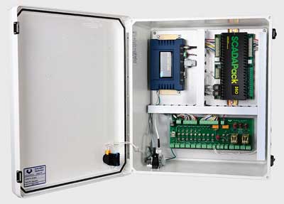 |
Fig. 11. New 32-bit hardware platform.
|
|
The WAG350 includes new features such as a user friendly operator interface, which uses a wireless Bluetooth radio to communicate to a rugged hand-held field PC or laptop. The 32-bit SCADAPack350* hardware also has an Ethernet port for communication systems that utilize Ethernet radios.
The software features a NIST 14 density algorithm for applications that require very accurate CO2 flow calculations. In addition to standard wellhead monitoring and control, the WAG350 also keeps track of daily- and monthly-injected gas and water volumes, as well as operating and shutdown times. The WAG350 also has advanced diagnostic features, such as Step rate testing, Step pressure testing, and Pressure falloff testing, that can be used to analyze oilfield formations.
Precision PCP coating. EXOKO Composites Co., Tulsa, Oklahoma, is using the latest advances in composite technology in the manufacture of Progressing Cavity Pumps (PCPs) and power sections as an exclusive licensee of this new patented Composite Progressing Cavity technology. This advanced technology allows for dimensional tolerances which, to date, have not been fully considered in the manufacture of conventional technology. The company’s ability to replicate parts to these tight standards offers users the same high performance from any rotor/stator combination.
In the older technology, the pump rotor was chrome-plated steel, shaped as a single helix; and the wear part, the stator, was an elastomer-formed double helix molded inside a steel tube. Although PCPs offer long life, abrasive fluids can shorten stator life. The interface between rotor and stator is lubricated by the fluid being pumped. However, if the pump is allowed to “run dry,” rapid stator deterioration results. Thus, the stator is the wear element, making it an expensive pulling operation to retrieve the damaged pump.
The EXOKO PrecisionWall* design reverses the technology by placing a precise elastomer layer on the rotor, and forming the stator out of hard composite material, Fig. 12. The rotor is now the wear element; more easily retrieved and replaced by pulling the rods. The stator normally will not need pulling each time the rotor is replaced.
 |
Fig. 12. Cross-section end view of composite coating on rotor within stator of 1:2 progressing cavity pump.
|
|
The precision, even-thickness elastomeric allows for uniform geometries and improved performance. The supplier has targeted a range of pump models in a single lobe (1:2) configuration starting with a Model 100. Displacement of this model is 100 bpd/100 rpm, with differential head/pressure ratings of 2,100 and 4,100 ft, or 900 and 1,800 psi, respectively. Future models will include higher volumes (to 4,500 bpd) and deeper depths (to 6,000 ft). 
* Trademark
|
THE AUTHORS
|
|
James F. Lea is the Kerr McGee professor, Mewbourne School of Petroleum and Geological Engineering at Oklahoma University. He holds BS/MS degrees in ME from the University of Arkansas, and a PhD in ME from Southern Methodist University. Lea worked for Sun Oil Co. as a research engineer from 1970�1975, taught at the University of Arkansas from 197�1978, was team leader of production optimization and artificial lift at Amoco EPTG from 1979�1999; was chairman of the PE Department of Texas Tech from 1999�2006, and recently assumed his present position at the University of Oklahoma. Lea is a registered professional engineer, and has authored several patents and many publications related to production and artificial lift. He received the SPE Production Award, has been SPE Distinguished Lecturer twice and received the Slonneger Award from the SWPSC.
|
|
|
Herald W. Winkler is former chairman, now professor emeritus and research associate, in the Department of Petroleum Engineering at Texas Tech University in Lubbock, Texas. He is presently working as a consultant in artificial lift, specializing in gas lift..
|
|
|
Robert E. Snyder, consultant, recently retired from Gulf Publishing Co. (GPC). He earned a BS degree in mechanical engineering from the University of Wyoming in 1957. Snyder served two years in the U.S. Air Force, worked 10 years for Marathon Oil Co., GPC for 29 years, and Completion Technology Co. for seven years. Within GPC, he served as engineering editor, editor of Ocean Industry and World Oil. He has co-authored several patents, authored many technical articles and made numerous technical presentations.
|
|


