Production Technology
Delivering a new water injection solution in the North Sea
PWRI application addresses challenges of severely corroded water injectors.
Manish Kumar and HonVoon Chin, Shell; and Alex Malcolm, Expo Group Integrated Services
Shell UK’s efforts to reduce oil-to-sea discharge at Nelson field, 120 km offshore Aberdeen in the Central North Sea, to comply with OSPAR regulations, have been complicated by the heavily corroded state of the Nelson water injectors. The state of these injectors posed a major challenge to successfully recovering the slot and executing a workover, which would allow produced water to be re-injected into the reservoir instead of being discharged to the sea.
BACKGROUND
Nelson field (Block 22/11) is located about 120 km east of Aberdeen in the Central Graben of the North Sea UKCS. The reservoir interval is the Paleocene, Forties sandstone, which comprises turbidite sandstones deposited in a proximal, mid-fan part of a large, basin-floor, sub-marine fan system. Production is about 40,000 bopd.
Four seawater injectors on the periphery of Nelson field had together injected over 235 million bbl of seawater, Fig. 1.
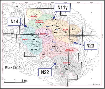 |
Fig. 1. Nelson field’s peripheral seawater injectors.
|
|
Nelson PWRI project. The Nelson asset needed to reduce the oil discharged to sea by 18% (compared with discharge in 2000) to meet 2006 OSPAR requirements. The base forecast showed a gap between forecast oil to sea and the OSPAR regulations.* Produced Water Re-Injection (PWRI) was selected.
| * The Paris Convention first introduced a 40 mg/L target for oil in produced water in 1974, which became an OSPAR (Oslo-Paris) standard in 1992. In 1998, United Kingdom Offshore Operators Association member companies (including Shell) made a commitment to achieve company annual averages of 30 mg/L oil-in-produced-water. |
|
The plan was to install new produced water injection facilities on the platform and work over the existing seawater injectors, allowing injection of the bulk of the produced water under reservoir-fracturing conditions. The combined modifications would give the system an injection capacity of 170,000 bbl/day. A number of producers and injectors were identified as donor wells for the project. Bearing other key considerations in mind (e.g., subsurface value, well integrity issues), the existing seawater injectors were judged to be the most suitable candidates for conversion into produced water injectors.
Annular leaks had been detected in all four seawater injectors. Water injection continued under short-term dispensation until December 2004, when it was shut down to preserve production casing integrity. The PWRI project was also seen as an apt technical solution to restore well integrity in these injectors.
In order to establish a baseline well status, Lead Impression Blocks (LIBs) were run into the water injectors. The LIB results were inconclusive, and a downhole camera was run in hole. The pictures confirmed that there was substantial damage to the production tubing and suggested significant damage to the production casing as well, Fig. 2.
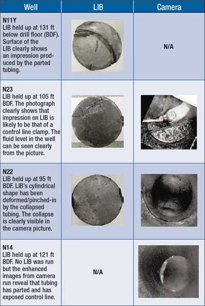 |
Fig. 2. Results of Lead Impression Block (LIB) and downhole camera observations in the Nelson field seawater injectors.
|
|
Multiple challenges. The integrity and lifecycle operability of the production casing was the primary concern. It was difficult to judge whether a “simple” workover would suffice or a full slot-recovery operation, involving the drilling of a new water injector, would be needed. An accurate measurement of the casing wall thickness was required. An Ultrasonic Imaging Tool (USIT) or a calliper log would have helped, but these options would only be possible after retrieval of the production tubing.
A way ahead was charted out to recover the completion strings from above the production packer, log the production casing to establish a baseline and pressure test to confirm integrity, and re-complete, Fig. 3. Based on the pressure test results, a decision could be made for re-completion or slot recovery.
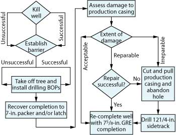 |
Fig. 3. A flowchart of the plan to address the production casing integrity and operability concerns for the injectors.
|
|
The flexibility required for such a plan was further complicated by the long lead times associated with OCTG. All personnel and equipment requirements had to be proactively identified; there was little room for reactive behavior.
WELL KILL
The first step was one of the biggest hurdles�the “killing” of the well. In subhydrostatic wells, which require protection against formation damage, the well kill has been achieved traditionally by placing a chemical pill at the reservoir perforations to block them off.
These chemical pills can be solids-based, using solids such as calcium carbonate, which are acid soluble, or solids-free systems, traditionally polymers like Xanvis, which can be chemically decomposed. The challenge was not the selection of the right pill but positioning the pill at the reservoir face. Given the limited access in the well, it was nearly impossible to selectively pump down a pill to the reservoir face. Coiled tubing-based options were considered. For example, a funnel device was manufactured that would help the coil to align the split halves of the tubing�but given the varied extent of damage, it was not a preferred solution. The traditional methodology could potentially require filling the entire well with the pill.
A solids-based system would have been appropriate, but, again, the placement of such a pill in the split tubing would be difficult. If sufficient solids landed in the annulus, it would increase the risks associated with the completion recovery. Additional risks involved loss of injectivity.
A solids-free system seemed much safer, as it would not greatly affect the fishing operations and the fluid would take the preferred path to the perforations. But the sub-hydrostatic nature of the Nelson reservoir was problematic. Nelson sands have very high permeability and low fracture-opening pressures (estimated as low as 0.47 psi/ft); i.e., any pressure above hydrostatic could initiate fractures in the formation.
Presuming that the fractures would remain closed while killing the well, a standard 200-ft perforated interval (k = 500 mD) would require an invasion radius of about 3.5 m to hold up a column of seawater. This equals about 1,500 bbl of Xanvis. The more likely scenario (i.e., fractures opening) would expose about 500 times more wellbore surface area (about 300,000 ft2) and thereby a much bigger invasion zone, which would necessitate over 500,000 bbl of Xanvis to plug the well�possible, but impractical. The use of a cross-linked polymer like Safelink was also suggested, but there was limited technical support for it to behave any differently.
Innovative solids-free systems (e.g., Schlumberger has used a polymer plug called ClearPill extensively in similar sub-hydrostatic applications in the Middle East) were also considered, but it was unclear how the pill could be spotted in the wells with limited or no access.
A measurable fluid level at surface in such operations acts as a visible hydrostatic barrier against hydrocarbons. Another “outside the box” approach was not to kill the well but to monitor its level deeper in the well from the surface. Echometers have been used extensively for this purpose in rod-pumped wells. However, these devices have traditionally been used as single-shot devices to provide a one-time indication of the fluid level in the well, not admissible as a barrier. Echometer Company has developed new “real-time” continuous data-relaying echometers, but these were still undergoing testing at the time and hence were not usable in the North Sea.
WELL ENGINEERING STANDARDS
These factors made the task of complying with Shell UK Well Engineering Technical Standards extremely difficult. The standard stipulates a minimum of two barriers in a live well when interventions are conducted. In a normal well, the fluid column (kill fluid) would form a primary barrier and a mechanical barrier in the tubing will form the secondary barrier, which will allow the Christmas tree to be taken off and a drilling BOP to be put on in order to conduct the workover. In this case, a deep-set barrier could not be placed in the well to get a fluid level to surface, nor could the fluid level be continuously monitored deeper in the well. The tree could have been removed to install the BOP without any barriers in the well, but the safer option was to go with at least a shallow-set barrier (e.g., some kind of a plug in the hanger or the tubing stump in the well) to minimize surface exposure to personnel. This meant that a dispensation against the “double barrier” policy would be required. Getting a dispensation on such a fundamental safety principle would not be easy.
To overcome this challenge, a detailed risk assessment was conducted involving the Well Engineering (WE) Technical Authority, the WE Operations Team, the Well Examiners and various WE peer teams. The intention was to brainstorm and document risks associated with the operation and incorporate mitigating measures. The wells had been under observation since the shutdown of water injection, and there had been no buildup of pressure in the wells�evidence that corroborated the wells’ inability for self-flow. The wells were regularly monitored for H2S and hydrocarbon (HC) gases to eliminate the risk of any stagnant gases in the well. The wells had been injected with over 70 million bbl each of seawater below the oil-water contact. All this evidence was used in support of a request for a dispensation against Shell’s double-barrier policy.
After many representations, a dispensation was granted with the following mitigating conditions:
- The well must be tested for H2S and HC gases before entry
- The well must be bull-headed with at least one well volume of H2S scavenger before entry
- Continuous H2S and HC monitoring must be available throughout the operation
- Casing-hanger and tubing-hanger seals and control lines must be tested for integrity before entry
- A shallow-set mechanical barrier must be set in the well and pressure tested to at least 500 psi over two cycles
- Exposure time of operations must be minimized
- Detailed well-control procedures must be in place for pulling/running completions
- The well must continuously be topped with seawater at twice the metal displacement rate while pulling tubulars or fishing BHAs
- Flo-sho devices and/or barrel counters must be checked physically and confirmed operational at every shift.
The WE approval was a major milestone for the project. The next task was prioritizing which wells to work over first.
WELL SELECTION
N11 and N14 were selected as the two primary candidates. These two wells had the highest injectivity of the four water injection wells, so any success with these wells would be a big step toward meeting the OSPAR targets. These wells’ higher injectivity also meant they were likely to have more damage to the production casing than the other wells. Finally, both had a small tubing stump below the hanger, which would allow the setting of a plug to remove the Christmas tree and install a BOP with at least one barrier in the well.
COMPLETION DESIGN
On the completion design side, there were quite a few challenges to overcome. The wells needed to be designed for two sets of operating parameters, the PWRI parameters for produced water injection and the Sea Water Injection (SWI) parameters for seawater fracturing purposes, Table 1.
The high injection rates required for the PWRI project drove the decision to select a 7 5/8-in. completion tubing as the injection bore. This was Shell E&P’s first use of this specification of tubing lined with Glass-Reinforced Epoxy (GRE) in Europe. The clearance of the 7 5/8-in. tubing string inside the 9 5/8-in., 53.5-lb/ft casing is less than 1/3 in. Although the 7 5/8-in. tubing string’s tensile loads were a cause for concern, the 25% improvement in injection performance it gave (compared with a 7-in. GRE tubing) was worth the engineering effort.
Extensive stress analysis showed that 7 5/8-in. tubing weight caused high compressive and tensile loads in the completion during both PWRI and SWI. This necessitated 125-ksi material for the completion crossovers. But the standard 125-ksi material (Incoloy alloy 725) was unavailable, so a new material had to be qualified for use. With detailed input from the material and corrosion engineering department, a new material (Special Quality Alloys 625 Plus alloy) was selected, qualified and used for the manufacture of the completion subassemblies.
Compression loads caused by hot produced water required that the production packer be rated to 125 ksi; i.e., a special packer had to be designed with an upgraded Incoloy alloy 725 inner mandrel and increased connection weight. The predicted high-completion pickup weight necessitated the redesign of the Tubing Hanger�Running Tool (THRT) and sourcing of an up-rated landing string. Well modeling showed tensile load failure at the Tubing Retrievable Sub-Surface Safety Valve (TRSSSV) caused by excessively cold seawater injection, so the seawater injection specifications had to be revised.
A number of other engineering studies were carried out to investigate the impact of PWRI on other hardware:
Wellhead growth. The thermal growth of the casing strings during hot PWRI operations was investigated. The increased temperature of PWRI caused casing expansion, leading to a displacement of the tree by up to 9 in.
Hanger thread-tubing compatibility. A finite-element analysis (FEA) was conducted to confirm connection characteristics between the 80-ksi, 625 Plus-clad hanger box thread and the 25%-chromium, 125-ksi tubing pin thread. The study confirmed the connection’s optimal makeup torque and tensile and compressive yields.
Tree and hanger erosion during PWRI. Because produced water contains fines, H2S and CO2, extensive work was carried out to finalize the material selection and design for the tree and hanger. Erosion studies carried out on the standard Nelson tree (90° angle of entry to tree) revealed that the 625+ internal cladding (3.6 mm thick) would be breached in less than one year of PWRI injection. This necessitated a different angle of entry to the tree, and a “half Y” universal tree configuration was selected. The erosion studies were re-done to analyze the effect of the selection, Fig. 4.
 |
Fig. 4. Comparison of a Nelson standard tree and a PWRI “half Y” block tree.
|
|
Based on the positive results of the various studies, the decision was made to use clad trees and hangers and change the standard Nelson tree to the half-Y block tree. This would require substantial engineering to adapt the new tree to the existing Nelson wellhead system and ensure the new tree with adaptor would physically fit into the Nelson well bay area.
WORKOVER
Work commenced on N14 in July 2005 using the platform-drilling rig to set the shallow barrier. An unsuccessful attempt was made to get a good impression of the profile in the hanger with an LIB tool string. The hanger plug was Run In Hole (RIH) but failed to set in the profile. After checking the tool function at surface, a second attempt was made, also unsuccessfully. The only option left was setting a plug in the tubing stump.
A Tubing End Locator (TEL) tool was RIH to determine the length of the tubing stump, which was less than 5 ft. The plug was then run and set in the stump. The plug was successfully tested to 500 psi over two cycles.
The plug acted as the primary barrier in the well, allowing the tree to be taken off and the BOP installed. The tubing hanger (complete with the 5-ft pup, control line and clamps) was then recovered. It was noticed that the plug-setting profile in the hanger had been completely washed out, which had prevented the plug from setting. It was clear that the tubing had split at the pin end of the pup just below the hanger.
Completion recovery. The first joint below the hanger was fished out of hole using an overshot, Fig. 5. The tubing had eroded significantly. A few more runs with an overshot assembly recovered small sections of tubing. In order to continue operations, it was critical to grip a thicker section of tubing to allow full recovery in a single trip.
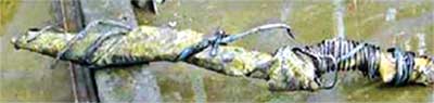 |
Fig. 5. The first joint of tubing below the hanger was recovered from Well N14 using an overshot. Notice the control line wrapped around the crumpled tubing section.
|
|
A washover assembly was RIH and worked to a 40-ft swallow. On Pulling Out Of Hole (POOH), a coupling clamp, a short length of control line and part of a coupling were recovered. The external cutter and washover assembly recovered about 40 ft of crumpling but thicker tubing.
The next assembly RIH was an overshot assembly complete with basket grapple. On engaging the grapple, the pickup weight was over 400,000 lb. This confirmed that “solid” completion string had been engaged. It also suggested that the Polished Bore Receptacle (PBR) in the string was locked down. Subsequent pickup to about 475,000 lb resulted in a sudden loss of tension. The assembly was POOH to recover a 3-ft section of tubing in the grapple.
As the PBR was locked down, it was necessary to cut the tubing below the PBR to allow its recovery. A landing string was RIH complete with an overshot assembly to allow running of a Radial Cutting Torch (RCT). After engaging the fish, slickline was rigged up and an RCT drift was RIH, but it hung up at the top of an existing tubing stump in the well. Three attempts to pass through were unsuccessful. An LIB was then RIH, which gave an inconclusive imprint. Subsequently, a downhole camera was RIH and revealed a “bird’s nest” made of control line in the tubing, which had caused the blockage. Gaining entry into the tubing was impossible with the bird’s nest on top.
The landing string was POOH, and a grapple, complete with overshot assembly, was RIH with intentions of “blind backing off” the string. Once the fish was engaged, torque was worked down the string. During this time, there were indications that the grapple was slipping, and on POOH, a 1,000-ft section of the completion tubing was recovered. The same assembly was RIH and the fish engaged. Some right-hand torque was applied to the string to avoid a shallow backoff. On picking up, the weight was lost, indicating the grapple had disengaged. A clamp was recovered from the grapple on POOH. The second blind backoff recovered about 11 joints of tubing, putting the top of fish at about 1,800 ft.
As the entire 10 ¾-in. production casing was exposed at this point, this was an appropriate time to do a USIT log to quantify the damage to the upper portion of the production casing, which would have probably suffered the most damage. The log results looked optimistic, and a pressure test to operating pressure confirmed the integrity of the casing. This meant that an expensive sidetrack would not be required.
With the “bird’s nest” out of the way, it was back to the base plan. The fish was re-engaged with an overshot assembly on 5½-in. tubing/landing string. A drift run was performed on slickline and an RCT was RIH. Although the first attempt was unsuccessful, the tubing was successfully cut below the PBR on the second attempt. While the tubing weight was being picked up, it broke free at 250,000 lb and was POOH complete with the PBR assembly intact.
The next step was to engage the stump below the PBR and release the anchor seal assembly from the production packer so that the new completion could latch back into the same threads. This mating would not be the sealing face but would provide a conduit for the injected water. Pressure containment would be achieved with another production packer set shallower than the current one.
The stump was engaged with the fishing assembly and rotated out of its packer. It was picked up and POOH, but there was no fish at the bottom of the assembly. On the second attempt, the fish was tagged 2 ft higher, engaged with a grapple and POOH. But, again, the fish had either slipped out of the assembly or had never been caught. A number of attempts were made with various configurations, but all were unsuccessful.
It was decided to shear the anchor seal assembly to allow recovery. On re-engaging the fish, a tensile pull-up to 80% premium pipe strength was executed and monitored for 5 min. When no movement was observed, the pull was increased to 100% premium pipe strength and monitored. After about 4 min., the string weight was lost. On picking up the string, an additional 20�30 kips above the normal weight was noticed. This was encouraging, because it seemed that either the seal assembly had been recovered or the production packer itself had been released completely. Unfortunately, on POOH, only a tubing stump with three joints of 51⁄2-in. tubing was recovered.
Change of plan. At this point, a decision was made to re-complete the well, without modifications, since it had experienced minimal loss of injection performance. It was clear that any additional fishing operations would both expose the personnel to additional risk and increase the risk of junking the well. There were minimal incremental benefits in injection performance to carry on recovering what was left of the production packer.
An extensive cleanup operation was conducted to recover any debris that might have dropped in the well. Runs were made complete with venturi junk subs, magnets and a scraper. The cleanup operation confirmed that the packer had not dislodged and there was no debris in the well.
A plug was then set at about 15,000 ft below drill floor (BDF) and the well was filled with inhibited seawater in preparation to run the USIT. The USIT was RIH on tractor to measure wall thickness of the production casing. The data was analyzed with the help of Schlumberger Data and Consulting Services. Based on the data, the well was successfully pressure tested to 4,785 psi, the lifecycle requirement for the PWRI wells. At this point, the well was suspended with DLT packers and the rig skidded to N11 to recover the completion.
WORKOVER PERFORMANCE
The N14 operations took less than 12 days to complete, with 1.2 days of NPT. N14 was then re-completed with over 15,000 ft of GRE tubing with NPT of less than 0.87 days. Recovery of the completion on N11 was fraught with similar problems to those faced in N14, so the same philosophy and lessons were used in the N11 workover. Over 15,000 feet of GRE completion was RIH in N11 with NPT of less than 0.84 days.
Injectivity test. A preliminary injection test was set up to test the newly completed water injectors using seawater (as the PWRI system was still being installed offshore). Both wells were tested to a high injection rate of about 60,000 bpd at injection tubing head pressure of 2,610 psi and 2,320 psi for N11 and N14, respectively, using the existing seawater injection system. The maximum injection rate was restricted by a 4-in. flowline in the SWI system. (This was replaced by a 6-in. line for PWRI system.)
Figure 6 shows the measured data from N11 vs. the well’s predicted injection performance curve. Only surface data was recorded due to the risks associated with running gauges in the well. The N11 well model indicates a reservoir fracture pressure of about 4,100 psi absolute, quite close to previously measured value of 4,000 psi absolute in 1997. This was a good indication of minimal to nil well injectivity loss due to the workover. The new 7 5/8-in., GRE-lined tubing had effectively reduced the pressure drop across the completion and increased the well injection capacity by about 50%.
 |
Fig. 6. Measured data from Well N11 vs. the well’s predicted injection performance curve.
|
|
In November 2006, the Nelson PWRI system began injecting Nelson’s produced water back into the reservoir without complication. Both N11 and N14 wells are injecting at a high combined rate of about 140,000 bpd.
CONCLUSIONS
The PWRI workover campaign delivered a number of firsts for Shell. It completed a challenging fishing and re-completion operation successfully with total recordable case frequency of zero. It was Shell’s first European well to achieve tubing replacement without a fluid level at surface (fluid about 3,000 ft BDF), i.e., the first live well the company worked over in Europe. It may be the biggest water injector installed in the North Sea. 
ACKNOWLEDGEMENTS
This article was prepared from SPE 106987 presented at the SPE/ICoTA Coiled Tubing and Well Intervention Conference and Exhibition held in The Woodlands, Texas, USA, March 20�21, 2007. The authors thank Shell UK and partners in the Nelson JV (Esso E&P UK Ltd., Total E&P UK Ltd., Petro Summit Investment UK Ltd., Svenska Petroleum Exploration UK Ltd. and Summit North Sea Oil Ltd.) for their support with the PWRI operations and permission to publish the results.
|
THE AUTHORS
|
|
Manish Kumar is a well engineer working with the Nelson team in Shell UK Ltd. He is currently project leader for an infill drilling campaign in the Nelson asset. Mr. Kumar has more than six years’ experience in various petroleum engineering roles. He holds a BS degree from the Indian School of Mines.
.
|
|
| |
HonVoon Chin is a petroleum technologist assigned to the Nelson asset in Shell UK Ltd. He has over 15 years’ experience in the oil and gas industry. In Shell Malaysia EP, he worked extensively on the Sarawak gas asset. .
|
|
| |
Alex Malcolm is a completion design engineer contracted by Shell UK in the Nelson asset. A geologist by background, Mr. Malcolm has over 20 years’ experience in the oil business. He earned a BS degree at the University of Derby.
|
|


