Produced Water Report
Troubleshooting produced water�
methods and lessons learned
Part 1 of 2: A task group addressed produced water problems on an FPSO with a focus on developing facilities, equipment and operations solutions.
John Walsh, John Fanta, William Bryson and Celso Toschi, Shell; John Petty, Modec International, LLC; Joseph Lee, Natco Group Inc.; Ted Frankiewicz, SPEC Services Inc.; and Melvin Stacy, Environmental Treatment Team, LLC
The E&P industry is seeing a rise in produced water-treating problems, and guidance is needed in the literature on how to troubleshoot such problems. The experience of a Produced Water Task Group assembled to address water-treating issues on an FPSO offshore Brazil may be helpful in those regards.
The Task Group was assembled in May 2005 to address problems associated with produced water treating and a growing inventory of off-spec water in the cargo tanks of an FPSO. While water production at the FPSO was still only one-quarter of the nameplate capacity, a significant fraction did not meet discharge quality requirements and had to be diverted to cargo tanks for later processing. The Task Group was formed to develop facilities, equipment and operations-based solutions.
The FPSO uses some interesting features that are not typically seen in E&P facilities. Some of these are clever, while others have not worked well. Some problems identified were:
� The facility is not designed to handle produced fluids that contain high loads of fine solids
� Some problematic recycle streams exacerbate existing emulsion problems
� There are no acceptable means of handling, reprocessing or disposing of solids
� Temporary equipment for treating water from well-flowback services is not available.
BACKGROUND
In October 2003, Shell acquired two deepwater fields that had been produced for about two years by another operator. Further production required implementation of a waterflood or other secondary recovery methods and well maintenance, such as scale-squeeze treatments and acid stimulation. Adding to these challenges, Shell had no other production facilities in the region. As part of a strategic entry into the region, Shell acquired the two fields and the FPSO.
Shell began producing the fields in October 2003. Production at the FPSO includes gas, which is pipelined to shore. Oil is stored on the FPSO and offloaded about once a month. Production targets have generally been met, and waterflood, scale-squeeze treatments and acid stimulation have been executed according to plan.
In this region, oil specifications and overboard water regulations are different from those in the Gulf of Mexico. In the GOM, EPA regulations require that a sample of discharged water be submitted for testing monthly. No one sample may have more than 42 ppm oil and grease, and an average of samples each month must be less than 29 ppm. Continuous online monitoring is not required. Where the FPSO is located, online water monitoring is required, and the water cannot be discharged if it exceeds 20 ppm oil and grease according to the calibrated online instrument. The BS&W requirement for the crude oil is 0.5%. In the GOM, the usual specification is 1.0%, and sometimes even this specification is hard to meet consistently. One advantage of an FPSO is that the oil cargo tanks give the crude oil an extra one to four weeks of residence time to dehydrate. Any water that drops out while the oil sits in the cargo tanks is pumped out of the bottom of the tank and processed later. This is done just prior to offloading an oil cargo in a process called �debottoming.� Experience shows that this strategy's effectiveness depends on the nature of the water-in-oil emulsion in the cargo tanks and on the roughness of the seas. If seas are rough and the emulsion is stable, the oil and water will not separate in the tanks. Thus, �debottoming� is not a reliable method.
Local specifications also require that there be less than 35 lb/1,000 bbl of salt in crude oil. For produced water of 80,000 mg/L Total Dissolved Solids (TDS) and BS&W of 0.5%, this is difficult to meet without a desalting system, so one was included in the FPSO's design.
In late 2004 and early 2005, water production began to increase, in part because of early seawater breakthrough from the waterflood. The rate of water production (about 12,000 bwpd) was far below the FPSO's 50,000-bwpd design rate. Nevertheless, water- and oil-treating problems were consuming significant operator attention. Water was being diverted inboard with increasing frequency, and the cargo tanks were filling up. The frequency with which pads were being cleaned out of the Intermediate Pressure (IP) separator and Bulk Oil Treaters (BOTs) was also increasing, as was the frequency of anomalously high BS&W in the product oil. The primary sources of produced water problems were a high level of fine solids, which stabilized both oil-in-water and water-in-oil emulsions, and a facility that was not designed to handle solids-stabilized emulsions.
TOPSIDES PROCESS
The oil/water separation process can be broken roughly into an oil train and a free water train, Fig. 1. The separators are in a 3:1:2 arrangement in the primary separation train�three primary separators, one IP separator and two identical, electrostatic BOTs. Oil from the BOTs goes to the oil cargo tanks for eventual offloading. Most of the produced water is separated from the oil in the three-phase primary separators. The IP separator is operated at 66°C, near its design temperature of 64°C. The primary separators, however, are designed for 41°C and are operated at a significantly hotter 64°C. The operators have increased the primary separators' operating temperature to improve the rates of settling and oil/water separation. This has some beneficial effects on BS&W and water separation. However, where scale mineral precipitates such as calcium carbonate and calcium sulfate are a factor, increasing the operational temperature may not provide a clear benefit because additional scale mineral solids will precipitate at the higher temperatures and either form emulsions or at least contribute to emulsion stability. It appears that the temperature has been adjusted already to the highest level the processing equipment allows. As watercut continues to increase due in part to further seawater breakthrough, it may not be possible to maintain these elevated temperatures, and/or the heat exchanger system capacity may have to be evaluated and improved.
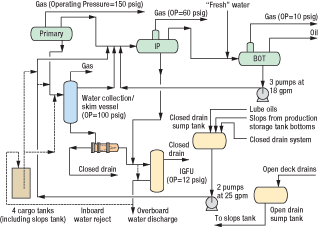 |
Fig. 1. The topsides treating system process, including operating pressures and pump rates. Dashed lines indicate intermittent or temporary piping.
|
|
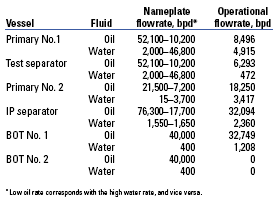
Oil and water flowrates were determined from process data software and material-balance calculations taken from June to October 2005. These were compared with nameplate capacities taken from the design vendor data books, Table 1. One BOT was online when the calculations were made. The flowrate values were reviewed with the design engineers, who indicated inconsistencies with the nameplate capacities and with the intended operation of some systems, Fig. 2.
| TABLE 1. Flowrates for June 2005 and nameplate design rates |
 |
|
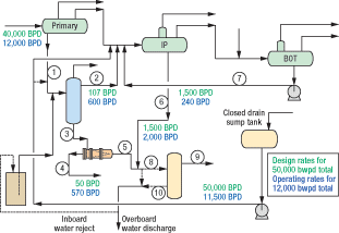 |
Fig. 2. Design flowrates and current operating flowrates for the water treating system. Although the current total flowrate is significantly lower than design, flowrates of certain important reject streams already exceed design rates. The circled component numbers correspond to the line numbers in Tables 2 and 3.
|
|
Produced water train. Early in the troubleshooting exercise, we cataloged problems on a Process Flow Diagram (PFD) of the separator train, Fig. 3. This tool allowed the team to summarize observations, unify the team's thinking and help determine priorities. It was extremely useful in focusing our troubleshooting efforts. Some of the factors identified were in the area of chemical treatment, such as hydrate inhibitor (methanol), and steps were taken to reduce the methanol treatment dose. Also identified was the need for additional scale squeezes to prevent the deposition of scale minerals in the wells and flowlines. The most important factors contributing to water-treating problems were a lack of solids-separation equipment, inadequate chemical treating facilities, excessive mixing of recycles back into the process streams and a lack of treatment facilities for off-spec water.
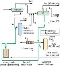 |
Fig. 3. Factors contributing to separation problems, identified with the source of data that indicates the problem and the severity of the problem.
|
|
As discussed above, the primary separators are three-phase separators. Free water is discharged to a water collection/skim vessel. From there, it proceeds to a hydrocyclone, then to the Induced Gas Flotation Unit (IGFU) before being discharged overboard. It is common to position a skim vessel downstream of the hydrocyclone, but its upstream position in this case is intended to provide steady flow and pressure as the water feeds to the hydrocyclone. This process configuration is needed because pressure and flowrates into the primary separators are subject to significant fluctuation. We expected the fluctuations in both liquid flowrates and composition because the separators receive fluids from a deepwater riser (3,000 ft of water), and these were confirmed.
Reducing fluctuations in the flowrate of water to the hydrocyclone helps to stabilize the position of the vortex in the hydrocyclone liners and thus, in turn, improve the hydrocyclone's oil-removal performance. When pressure and/or flowrate fluctuate significantly in a hydrocyclone, the interface between the reject oily water stream and the forward flow of clarified water becomes turbulent, and the separation of oil and water deteriorates significantly. The discharge water from a hydrocyclone can contain some oil drops in the range of 100 to 200 microns or larger. Coalescence of these drops can be achieved in a skim vessel placed downstream of the hydrocyclone. Instead of a skim vessel, this FPSO has an IGFU, which provides for the coalescence and removal of the large oil droplets.
One concern is the handling of the reject streams from both the hydrocyclone and the IGFU. These reject streams are typically high in solids. Both streams go to the closed drain tank, a major source of problems in the system. It is too small to provide any beneficial settling time, and it catches a wide range of fluids that can combine to create a cocktail of emulsifying agents. To make matters worse, discharge from the closed drain tank sends the fluids through high-speed centrifugal pumps and valves into the feed to the IP separator. It should be noted that the primary fluid entering the IP separator is an oil-continuous stream.
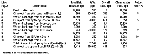
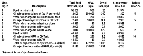
To design an alternate route and treating system for these reject streams, we conducted a characterization and a material balance to understand the volume of fluid requiring treatment. Two sets of material balances were determined for the produced water train. The first set described the system as operated in October 2005, producing 12,000 bwpd, Table 2. The second set used nameplate design flowrates where available. For other values, we extrapolated existing rates to the nameplate capacity of 50,000 bwpd, using the same feed/reject ratios that were in operation at 12,000 bwpd, Table 3.
| TABLE 2. Flowrates for October 2005 in the produced water treating system |
 |
|
| TABLE 3. Extrapolated flowrates for 50,000 bwpd based on current reject ratios |
 |
|
As operated, the produced water system has reasonable reject rates. These were mostly determined by adjusting the reject rates such that estimated flowrates would match measured flowrates. For example, the oily water reject from the water collection/skim tank has an estimated flow of 600 bpd, which gives a reject rate of roughly 5%. The measured BS&W fluctuated between 40% and 60%, so we reported 50%. The reject rate for the hydrocyclone was estimated at 5%, which is reasonable for the model and differential pressure ratio of 1.59.
Typically, as produced water proceeds downstream it becomes cleaner, with decreasing oil content. In the current process, the design flowrate of the oily reject streams is roughly constant as a percentage of flow and is much lower than actual operating experience. It is not clear why the hydrocyclone reject rate was designed as such a low number (0.1%, in contrast with an operating value of 5%), since hydrocyclone performance curves are well known. This suggests that the system was designed without considering industry norms for reject rates, a suspicion the designers confirmed. Instead, the water-treating system was designed using software based on thermodynamic considerations and that, to our knowledge, does not have oil/water separation modeling. Thus, the conclusion can be drawn that reject rate is one of the more important parameters for designing and troubleshooting a produced water system.
PRIMARY SEPARATORS
The design of the primary separators makes them sensitive to the FPSO's motion and introduces slugs of oil into the water-treating system. The following are the main problems with the design of these vessels:
� Level control in the liquid-packed section does not dampen slugs: This is because the liquid-packed section is small for the throughput of each vessel. As a result, the control system must react quickly by allowing the water discharge valve to swing open and closed quickly. This transmits surges of water downstream, and the rapid water-discharge rate can pull slugs of oil into the outgoing water stream.
� There is a potential short-circuit path for fluids through the vessels: Some fraction of the oil that routes through the primary vessels has only a few seconds of retention time.
� The dimensions and shape of the liquid-packed section cause a liquid vortex: The section is roughly spherical, which encourages vortex formation and allows oil to curve around the hemispherical dome into the water-discharge line. The control system's fast reaction speed aggravates this problem.
� The location of the water-discharge nozzle in the liquid-packed section makes the vessel sensitive to motion: The nozzle is too close to the end of the vessel for a floating unit such as an FPSO. For such systems, fluid-discharge nozzles should be closer to the center of a chamber or midway between a set of perforated baffles to avoid motion sensitivity. In addition, the approach to the nozzle should be diffuse with a relatively slow velocity to avoid down-coning of oil into the water outlet.
These are inherent design flaws that could be mitigated following a cost/benefit analysis. Vessel internal modifications are often costly in terms of manpower, re-certification and shutdown time.
IP SEPARATOR
The separation process' 3:1:2 configuration (three primary separators, one IP separator and two BOTs) makes the IP separator an obvious location for a potential bottleneck. As with any separation problem, the first parameter checked was vessel efficiency, defined as the ratio of inlet BS&W to outlet BS&W, Fig. 4. There is a wide range of inlet and outlet BS&W values, which may have resulted in part from recycles that dump into the IP vessel. According to the BS&W efficiency data, every few days the outlet BS&W would rise to that of the inlet BS&W, reflecting a dramatic drop in the efficiency of the vessel. The operators interpreted this correctly as the result of an emulsion pad forming in the vessel. This was verified by draining the entire tank to take fluid samples and performing solids and BS&W analyses.
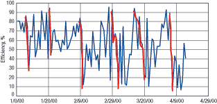 |
Fig. 4. IP separator BS&W efficiency, defined as (BS&Win � BS&Wout) x 100/BS&Win .
|
|
In discussions with the operators, one concern raised was a lack of piping that would allow draining of the IP separator when needed to eliminate the pad. The only piping available to drain the vessel has a tie-in with the produced water through a bypass line to a point downstream of the deoiling hydrocyclone, Fig. 5. The total inventory of fluids from the IP vessel (about 300 bbl) required about three hours to drain. The volume of produced water in that time was 1,800 bbl. Thus the IP fluids (300 bbl) combined with the produced water (1,800 bbl) results in 2,100 bbl of off-spec oil/water emulsion, which cannot be discharged overboard because of high oil content, and which was sent to the cargo tanks for later processing.
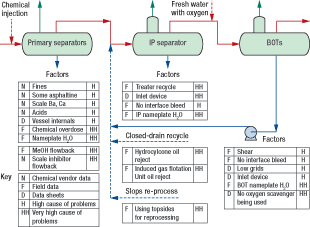 |
Fig. 5. Routing of fluids from the IP separator dump manifold. When the operators dumped fluids from the IP vessel, they would mingle with the entire produced water stream, thus creating a much larger stream of off-spec fluids.
|
|
A medium-term solution would be to provide a route for dumping the IP vessel's contents that would not mingle them with the produced water stream. Preferably, the IP dump fluids would go directly to the off-spec cargo tank for subsequent slops treating. A long-term solution would address and eliminate the source of the emulsion pad that requires regular draining of the IP separator. Alternatively, an interface drain line could be installed that would allow removal of the interface pad without draining the entire vessel. These options are discussed in next month's article.
DESALTING
The IP/BOT system is designed to provide two-stage desalting. A �fresh water� stream is added upstream of the BOT, Fig. 1. Water discharge from the BOT is then routed to the inlet of the IP separator. Thus, the crude oil is �washed� in both the IP and the BOT, which results in two-stage desalting.
While this, with sufficiently efficient mixing, can be an effective means of crude-oil desalting, we determined through settling tests that significant quantities of water-in-oil emulsion were being generated by this water recycle. Simplified mass-balance calculations show that by injecting 5% wash water with suitable mixing ahead of only the BOT, two-stage desalting is not required to achieve 35 lb/1,000 bbl at the BOT outlet. Based on these calculations, we recommend that appropriate amounts of wash water be injected at the BOT inlet and that recycle of water and oil from the BOT to the IP separator be discontinued.
As the volume of seawater from the waterflood operation increases, salt content in the crude going to the BOT should decrease, and less freshwater should be needed to achieve the required desalting. It should also be noted that the introduction of oxygen-laden freshwater for desalting into the process stream is extremely detrimental because it oxidizes dissolved iron, creating iron hydroxide solids, which will contribute strongly to the stabilization of the emulsions. Thus, the injection of an oxygen scavenger was recommended for the freshwater used in desalting.
BULK OIL TREATERS
The two BOTs are horizontal treaters, which means the fluid flows horizontally through a series of vertical grids. In a horizontal treater, water droplets that are large enough to flow downward do not have an opposing upward flow of oil, as would be the case in a vertical treater. Horizontal treaters work well for light crude where there is little or no tendency to form an interface emulsion pad. However, for emulsified crude oils, the advantage of horizontal flow can be negated by the presence of interface emulsions. One problem is that some fluid can flow under the grids, bypassing them in a short circuit to the oil discharge port. To minimize this problem, the grids extend very low in the vessel�much lower than in a vertical flow design�reaching below the wet oil and into the emulsion or pad layer, where the dielectric of the fluid is so low that the grids can short out. One way to minimize this problem would be to install weir plates below the grids to prevent the fluid from bypassing them. However, this can create dead zones within the vessel and force emulsion and wet oil upward into the grids. As previously described, this excess water going through the grids would increase the conductivity of the oil and reduce the electrostatic treating efficiency.
Grid placement is a difficult design decision for horizontal treaters. If the grids are hung low, or if weir plates are used, the fluid shorts out the grids, and if the grids are hung high, some of the fluid bypasses the grid section. For crude oils that have a high solids content or an emulsion that is difficult to resolve, pad formation is inevitable and this interface pad may cause the grids to short out.
As built, the BOTs have no interface bleed, and if ever a crude oil needed an interface bleed, this is it. More than any other design feature, the selection of horizontal treaters without interface drains is an indicator that the facilities were not designed with the crude oil properties of this field in mind. The design might have worked well for a light condensate, but it is inappropriate for medium-gravity crude (27�29° API) with high loading of fine solids.
The Produced Water Task Group recommended:
� Raising the grids and adding matrix plates between them to reduce the fluid that can flow under the grids
� Adding an interface bleed system, or raising the grids and extending the existing bottom plates
� Electrically bypassing the first several grids, since they are the ones most likely to short out.
Specific options include installing an appropriately designed interface drain header, preferably connected to an existing drain nozzle on the vessel. Fortunately, one feature of the existing system is that each of the two BOTs is large enough to handle 100% of the current oil production alone, so work can be done on one of the treaters while the other remains in service.
All of these options will require significant engineering and installation work, and some may actually risk hurting performance. For example, matrix plates might become plugged with solids and cause extreme fluid short circuiting. Therefore we recommend that equipment vendors be contracted to evaluate potential modifications that would improve the watercut distribution and BOT performance with minimal risk. Almost certainly there would be value in conducting a computational fluid dynamics study on the vessel as it is and any proposed modifications.
INDUCED GAS FLOTATION UNIT
The IGFU is a vertical, cylindrical vessel into which gas is injected as fine bubbles. The gas bubbles then rise to the liquid/gas interface with oil droplets and oil-coated solids attached.
One of the Task Group's more interesting discussions occurred when we shared the results of the water mass balance with some of the facility's original designers. The operating reject rate from the IGFU is roughly 10% of the feed flowrate, Table 2. The design assumption was that less than 1% of the feed would be rejected. In effect, the designers had planned for the IGFU to act as a combined flotation unit and slops tank.
In a typical produced water-treating system, the reject stream from the flotation unit is routed to a slops vessel, where oil from the reject and water gravity settle. The water is pumped off to the wet-oil tank for recycle processing in the produced water train, and the oil from the slops tank is pumped into an upstream vessel such as a BOT or simply (since the volume of oil is low) mingled with sales-quality oil. The intent is to route the oil into the product stream. This arrangement allows a relatively high reject rate from the flotation unit and skims the oil and oily solids quickly to prevent their re-entrainment into the produced water. The slops tank provides further oil/water separation such that only about 1% of the entire water flow ends up as oil reject from the slops tank. Such an arrangement works well provided that excessive clarifier chemical is not used.
This FPSO's designers wanted to combine the functionality of an IGFU and a slops tank by making the flotation unit, in effect, a two-stage unit, thus eliminating the slops/wet-oil tank. The first stage of the IGFU was intended to provide gas-bubble attachment to oil drops and oily solids and float them to the top of the liquid/gas interface for collection and separation. The second stage, in the top of the same vessel, would slowly skim the contaminants into a spillover bucket, as in a typical flotation unit. However, the spillover bucket would not dump immediately. Instead, it would allow residence time for oil-water separation, as in a typical slops tank. Only after hours of residence time would the contents of the spillover bucket be dumped. Such residence time, in effect, would allow a slops-treating stage. In this configuration, the reject rate of the flotation unit could be reduced dramatically to 1% from the more typical 5�10%. However, in practice, oily solids and stabilized oil droplets in the produced water do not coalesce into a coherent surface layer. Instead, they become re-entrained into the flow of water through the IGFU and are discharged overboard along with the produced water. A fraction of the oily solids thus end up on the surface of the seawater, contributing to the formation of a sheen.
To handle the oil reject, the downstream processing equipment must be able to separate a small fraction of oil in water. This fluid should not be routed to the oil cargo tanks, as is now the case, but rather to the slops-treating system.
The flotation unit's oil-reject control system and the closed drain vessel's level control/pump system cause significant surges of oily emulsified water to feed into the IP separator, where complex and stable oil-in-water emulsions form. Fixes for the IGFU control problem are in progress. 
The second part of this series, to be published next month, will discuss troubleshooting we conducted regarding chemical properties of produced fluids on the FPSO.
|
THE AUTHORS
|
|
John Walsh joined Shell in 1991 after obtaining a PhD in fluid phase equilibria at Johns Hopkins University. He joined Shell Exploration and Production Co. in 2001 as the chemical engineer for the Mars Tension Leg Platform. Since 2004 he has been involved in water treating problems across Western Hemisphere Shell assets.
|
|
| |
John Fanta, PE, has an MS degree in mechanical engineering from Rice University. During his 33 years with Shell, he has studied water treating onshore and offshore California, in the GOM and most recently in the Campos Basin, offshore Brazil.
|
|
| |
Bill Bryson is the subsea and topsides surveillance manager for Shell Brazil Exploration & Production. He worked for Shell in the North Sea for 20 years on projects ranging from instrument engineering to installation management.
|
|
| |
Celso Toschi is a chemical engineer with an MS degree in process engineering. He has 27 years' experience in the Campos basin, five of which are with Shell Brazil on production chemistry application in the Bijupira and Salema offshore fields.
|
|
| |
John Petty, PE, has been an engineering consultant to Modec International LLC for six years on the design and operation of the FPSO Fluminense. He has 45 years' experience and holds a BS degree in chemical engineering from Mississippi State University and an MS degree from Louisiana State University.
|
|
| |
Joseph M. Lee is director of process solutions at Natco Group Inc. He has 30 years' experience in the oil and gas industries with firms including Amoco, BP and Haliburton. He holds BS, MS and PhD degrees in chemical engineering. He can be reached at jlee@natco-us.com
|
|
| |
Ted Frankiewicz is a process engineering consultant with SPEC Services Inc. He has a PhD in physical chemistry from the University of Chicago. He has nearly 30 years' experience in oilfield processing, separations equipment design and produced water treating. He can be reached at tfrankiewicz@specservices.com
|
|
| |
Melvin Stacy graduated from Mississippi State University in 1963 as a mathematics major. He joined Baker Hughes in 1967 in production chemical applications and worked for Baker Hughes' water treating division from 1985 to 2001. Since then he has worked as a water treating specialist and consultant.
|
|
|


