Deepwater Technology
Outer riser system for Anadarko's
Constitution spar allows dry trees
Development and installation of new threaded riser connections reduce riser weight, opening deeper waters for TTR development.
John Cromb, Anadarko Petroleum Corp.; Yves Delepine, Technip USA; Tim Bedore, Weatherford International Ltd.; Bruce Bradley, VAM USA; Gabriel Roussie and Jacky Massaglia, V&M Tubes
Development of deepwater fields using dry-tree systems, instead of subsea systems, provides many benefits. As operators have developed fields in deeper water, costs and technical challenges of providing top tension for these riser systems have increased. Measures to reduce the weight of the risers, while maintaining the required fatigue performance, enable use of the top-tensioned risers (TTR) in these deeper waters.
Higher grade risers with threaded and coupled (T&C) connectors allow for significant weight reduction of the riser and provide feasible solutions for development of these deepwater or high-pressure fields, where surface production is preferred.
Riser and facility design teams must address many challenges in the design, manufacture and installation of the TTR. The integration with other parts of the riser system, the onshore fabrication of pre-assembled components, the riser installation equipment and long-term riser integrity management issues are all critical aspects of the development. This article presents the lessons learned during the development, fabrication and delivery of the 95-ksi T&C outer riser system for Anadarko's Constitution spar.
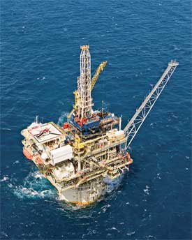
Constitution field is located in about 5,000 ft of water in the central Gulf of Mexico, Fig. 1. The Constitution spar development consists of six wells with dry trees using a dual-casing riser system. Anadarko's previous spar completions (Neptune, Nansen, Boomvang and Gunnison) used single-casing production riser systems. Some of the technologies used for the Constitution's implementation were unique, and many applied technologies were carried over from experiences at Anadarko and other operators. A steep learning curve was realized during the program; these learnings were captured and applied successfully to this development.
|
Fig. 1. Anadarko Petroleum's Constitution field spar facility sits in 5,000 ft of water in the central US Gulf of Mexico. Photo courtesy of Anadarko Petroleum.
|
|
DEVELOPMENT PHILOSOPHY
A completion philosophy is a planning tool for each field that states the underlying principles for completion design. The completion philosophy for Constitution field was agreed upon by the entire asset team prior to any well completion design work. This proved beneficial throughout decision points in the well program, especially when critical resolution was needed. Substantial discussion was directed to the development of a basic design for the field's TTR barriers: single-casing vs. dual-casing barriers.
Initially, Anadarko performed a risk assessment of the two riser types. Additional internal information was developed to quantify the anticipated shut-in tubing pressure (SITP) for each of the dry-tree wells. Anticipated well completion and maintenance operations were identified for consideration in the final design, as were comparisons to other dry trees in service or planned by other operators. The following influential drivers were considered in the selection of the field's riser �barrier� system:
� Well control
� Drill-through
� Gas lift options
� Tubing leaks for a dual-casing riser.
These barriers are normally available with dual-casing or single-casing risers. However, use of a single-casing riser may have a limiting effect on the workover or recompletion operations performed by a platform rig during the field's life. Specifically, sidetracking to a new bottomhole objective would subject the innermost riser to rotational wear from the drillstring. In the case of a single-casing riser, wear in the casing wall would compromise at least one of the two pressure barriers and compromise well control, particularly during the early life of a well when pressures are highest.
Remediation can be effected procedurally by maintaining completion fluids above the weight required for well control. At Constitution field, sub-seabed fluids in the range of 1.5�2.0 ppg heavier than the minimum for hydrostatic balance with an intact riser would be required. If bottomhole pressure at TVD is 11�12 ppg in 5,100 ft of water, then 12�13 ppg will be required, if the riser is compromised and the weight of the riser fluid is replaced with seawater. The same scenario would exist during production operations and well completions, and operating procedures must address the issues for safe well control. The low fracture gradient prevented drilling/sidetracking the Constitution well with enough mud weight to offset the loss in riser margin to seawater gradient.
In light of the information gained, it cannot be assumed that additional drilling operations through the production riser would not be undertaken during the life of the wells. For the specific case of future sidetrack drilling or other activity requiring substantial rotation inside the inner casing string from the platform-mounted rig, a dual-casing riser was recommended.
Use of a dual-casing riser with a live annulus was preferred for simplification of the well completion (no dual completion with mudline packer from mudline to the surface). While a dual-casing riser is more complex and requires additional wellhead components, the benefits of simplified dry-tree design, operational flexibility and enhanced safety weigh heavily in its favor.
RISER CONNECTION SYSTEM
Two types of connection designs are normally considered for dual-casing TTR installed on spar platforms�welded and T&C connections. Welded connections are usually reserved for the more fatigue-prone outer riser joints, whereas T&C connections can be used in the less-stressed parts of the risers. T&C connections are also commonly used for the inner production riser strings.
For the project, the lighter weight characteristics of T&C connections were particularly attractive, since the riser requirements were finalized after the spar size, and particularly once the center-well size was frozen. With the height of the buoyancy cans being limited by the spar truss geometry, the weight savings from T&C connections proved valuable. Similarly, the replacement of a welding process with a highly automated machining process yielded cost savings.
These advantages were balanced by the need to implement a full qualification program at the mill, followed by extensive tests to ensure that Vallourec & Mannesmann's new high-fatigue, 12 ¾-in. Sea VAM TTR, T&C connection could be manufactured within the specified tolerances and reliably made-up offshore. Anadarko's willingness to implement a new connection design on a real production project was a key to this joint endeavor's success.
NEW T&C RISER CONNECTORS
The use of higher-strength pipe in dry-tree systems for deepwater applications enables the use of lighter wall pipes and reduces the weight for a given pressure. For example, the 12 ¾-in., 0.492-in. nominal wall, 65.10 lb/ft T&C outer risers had minimum yield strength of 95 ksi and a pressure rating of 6,420 psi. For six risers utilizing 4,200-ft T&C per riser, the total weight of the T&C section would be 1,640,520 lb (air weight). To achieve the same pressure rating with a welded system and maximum yield strength of 80 ksi, the required wall thickness would be 0.585 in. (76 lb/ft plain-end pipe weight). The combined weight of six 4,200-ft risers with this wall thickness is 1,905,300 lb. This would be roughly 275,000 lb more than the T&C riser, without including the welded connector's weight.
The higher grades lead to significant riser weight reductions, but prohibit the use of welds to connect the pipes. The elimination of welds leads directly to the need for high fatigue-resistant T&C connectors that can be manufactured on grades up to 125 ksi or higher. Since the T&C concept does not require welding, it also offers the possibility of using sour service grades and reduces costs, compared to forged and welded connectors. T&C risers can be installed with casing-type running equipment and similar procedures. Higher-torque casing tongs with non-marking dies and back-ups can be used to run T&C riser strings.
Several critical components are required for a deepwater riser connector�a seal to contain internal pressures that may be experienced over the life of the well, a fatigue-resistant thread form and, in the case of an outer riser, a barrier to prevent seawater intrusion into the connector throughout its service life. Previous T&C riser designs have been casing connectors modified to perform as riser connectors.
The 12 ¾-in. connector used for the outer risers on this project was a totally new design consisting of three parts�an internal metal seal to contain internal pressures, a high fatigue-resistant triangular thread form and a totally new external metal seal to prevent seawater from entering the connections. In summary, high fatigue resistance, easy running and fatigue-compliant external sealing were the main elements specified for the T&C outer riser connector used.
T&C risers were selected for inner production risers and outer risers. The inner production riser consisted of 9 5/8-in., 47 lb/ft VAM TOP FE in P110 and Q125 grades, and 12 ¾-in., 65.1 lb/ft Sea VAM TTR in VM95HC grade was qualified and used for the outer riser.
OUTER RISER CONNECTION DEVELOPMENT
The target for fatigue resistance was set to a Stress Amplification Factor (SAF) of 2.0, according to DNV-B curve, since the material is not welded. This corresponds to a 200-yr service life (20-yr service life x 10 design factor), which satisfies the needs of most dry-tree systems. To address fatigue, an innovative triangular thread profile was designed, evaluated in detail with Finite Element Analysis (FEA), and validated with full-scale tests, Fig. 2.
 |
Fig. 2. Features of the 12 ¾-in. T&C riser connection include a new external metal seal, a high fatigue-resistant, triangular thread and an internal metal seal.
|
|
The second innovation was in the external metal-to-metal seal to prevent seawater from entering the connection. This design, compared to elastomeric seal rings, allows for fatigue compliance, simplifies running and ensures seawater exclusion. Moreover, the combination of this external seal with the triangular thread profile provides a global increase of the connector's fatigue resistance, due to a stress-relieving effect on the connection's hot spots. The performance of the external seal was tested and validated under combined load tests (external pressure, tension, compression, bending) before and after fatigue testing. Due to their innovative designs, the external seal, thread form and internal seals have been patented.
OUTER RISER QUALIFICATION
The qualification program consisted of sealability testing under combined loads (ISO 13679), and full-scale fatigue testing. The challenge was to complete the testing in the project's time frame (about six months), knowing that pipe procurement for threading test samples can take up to three months. It was decided to use ongoing in-house ISO and fatigue tests being performed on 13 3/8-in., 68 lb/ft pipe to qualify the 12 ¾-in., 65.1 lb/ft pipe by extrapolating the physical results and additional FEA. This approach helped save critical time and allowed for qualification program completion in due time.
The ISO test was completed successfully on four connections with the most critical geometric configurations, using the ISO 13679 CAL III procedure. The testing comprised several make-ups and break-outs, followed by sequences of combined tension, compression and bending, with gas internal pressure and water external pressure.
Six samples were tested on a resonant fatigue test frame, which uses a rotating eccentric mass to produce loads and alternate bending moments in the connection. Three different stress ranges were used, submitting the samples to 1, 4 or 34 million cycles. A mean tension load was applied on half of the samples using internal pressure and the capped-end effect. The testing was successfully completed with all samples above the SAF 2.0 target curve for DNV-B, Fig. 3.
 |
Fig. 3. S-N graph of fatigue qualification for the Constitution project, using 133/8-in., 68 lb/ft SEA VAM TTR pipe.
|
|
OUTER RISER INDUSTRIALIZATION
The industrialization of this new connector required important support and follow-up from the engineering team. Training people for a completely new product featuring a serial number 1 design was crucial, and lessons were learned from the manufacturing through the installation processes. Resources were adapted for support, and open communication among all parties was a key success factor.
LESSONS AND TESTING
Once the operator accepted the ISO and fatigue qualification testing for this new-generation riser connection, there were still lessons to be learned during component assembly and full-scale rig testing.
The first lesson came during onshore assembly of 123/4-in. outer riser couplings onto the crossovers at the bottom of the riser string. Initially, the radial force applied by the post-mill, bucking equipment to the unsupported couplings was beyond the couplings' material yield. Although it was not visually evident, the couplings were deformed, and some gallling was experienced during coupling buck-on.
To correct this problem, a maximum radial force was determined using FEA, the connection specifics and bucking equipment. This led to defined setup parameters for the bucking equipment. Onshore coupling installations were completed without problems. Full-scale rig testing was performed to validate connector integration, the running equipment and to define field procedures for making and breaking connections before going offshore.
Comprehensive and rigorous testing ensured that the procedures developed for offshore installation were accurate and thorough. More than 20 joints of outer riser were used during this test, so that all installation process aspects were covered. The joints were subjected to severe misalignment, different thread compounds, varied thread compound quantities, multiple make/breaks per connector and many other tests. This testing also validated all of the running equipment.
Additional lessons were learned in full-scale rig testing. During make-up, in the area gripped by the power tongs, the Thermal Sprayed Aluminum (TSA) coating could flake and contaminate the external seal and thread compound. Due to the abrasive nature of TSA particles, they could scratch the external seal, which was unacceptable. This concern was eliminated by placing a temporary shield on the pipe above the connection during make-up. Prior to going offshore, the running contractor fabricated a laminated canvas �skirt,� which was attached by Velcro. This proved successful, and no problems were encountered during riser-running offshore.
OFFSHORE RIG INSTALLATION
All of the T&C riser joints had TSA applied to the exterior. The joints were then placed in bolsters and transported to a Louisiana staging yard. At the yard, and prior to shipping, all of the joints had their connections cleaned and inspected, and thread-running compound was applied. Each bolster was identified, and the individual joints and their respective lengths were recorded. Once delivered offshore, the bolsters were offloaded to the spar in the proper running sequence. This procedure was followed throughout the first five riser string installations, and it proved very effective.
The outer casing string for each riser consisted of welded connection joints at the riser's bottom and top (bottom stress joint and spar-keel to joint interfaces), crossover joints for the transitions between welded and T&C connectors, and T&C for the remaining ~81% of the string, Fig. 4.
 |
Fig. 4. The top-tensioned riser configuration included both welded and threaded connections.
|
|
The average outer riser installation run time improved between the first and fifth wells by 42% (71 hr vs. 41 hr) and the inner riser run time improved by 46% (43 hr vs. 23 hr), Figs. 5 and 6. A downward time trend was seen throughout the programs. The project had less weather-related downtime compared to the Gunnison and Boomvang developments, Table 1. Its efficiencies were directly related to previous lessons learned, and the teamwork among Nabors, Weatherford V&M and Anadarko personnel.
 |
Fig. 5. The outer riser installation total run time improved 42% over the project.
|
|
 |
Fig. 6. The inner riser installation total run time improved 46% over the project.
|
|
| TABLE 1. Comparison of riser installation percentages |
 |
|
PROCEDURES AND EQUIPMENT
The running procedures were the same as generated from the full-scale rig testing. Each joint of the riser string was removed from the bolsters according to a predetermined running order. The 40-ft lengths of each T&C riser allowed them to be lifted into the vee door in typical casing running fashion, saving handling time.
A joint was lifted with a stabberless single joint elevator and stabbed into the coupling in the rotary. After stabbing, the joints were hand-started five or six turns using strap wrenches. The use of a weight compensator and stabberless hydraulic positioning system aided hand-starting. Once the connections were made-up with the strap wrenches, the protective skirt was applied with the Velcro strap, and automated riser tongs and back-ups were used to tighten the connections. Since the riser spider was located one deck below, the joints could be lowered to a point where the coupling was about 5 ft from the rig floor. This improved running efficiency and personnel safety, since no stands or tables were needed. All of the rig crew and riser personnel worked at rig floor level.
Each connection make-up was computer-monitored for torque, turns and time, Fig. 7. During the running of the first five riser strings, only four connections had to be backed out. All of these connections were cleaned, inspected and remade into the string. No joints were rejected or laid out due to make-up issues. The 0% reject rate was a notable success and largely due to planning and previously performed full-scale testing, Table 2.
 |
Fig. 7. Typical make-up graph for 123/4-in. Sea VAM TTR showing torque, turns and time.
|
|
| TABLE 2. Connection make-up parameters for 12 3/4-in., 65.10 lb/ft VM95HC Sea VAM TTR-NA T&C connector |
 |
|
SPECIALIZED EQUIPMENT
Detailed running and handling procedures were developed to ensure successful riser joint installation. Some of the specialized equipment and requirements were:
� Crossover and coupling installations. The installation of the couplings to the weld-on to the T&C crossovers required a proprietary hydraulic gripping system, outfitted with a non-marking die system to protect the TSA coating. The tong used to make-up these crossovers incorporates a hydraulic tri-gripping system with full-face aluminum inserts. This system has over 320° of circumferential contact to ensure that the coupling and tube-wall integrities are not compromised. This system also incorporates a relief valve to ensure that predetermined radial forces are not exceeded during gripping.
� Specialized running equipment. A single-joint compensator alleviated the set-down weight on the connector's stabbing flanks during make and break operations. The tong weight compensator allowed the tong to follow a joint's relative movement during make-and-break operations, while the remotely-operated riser tong with PLC logic provided a completely �hands free� environment. A derrick-mounted, remotely-operated stabbing device ensured true vertical alignment with PLC-logic repeatability, and alleviated guess work locating well center on joint installations.
� A remotely operated riser spider and elevator minimized human intervention. The riser spider was modified to incorporate a hydraulic, splitting base plate that allowed passage of all large OD string components without having to be removed from well center. The rig's spider deck was modified to incorporate the riser spider and support string weight, which lowered the connector height and created a safer rig floor environment.
CONCLUSIONS
Previous experience on spar projects had a significant impact on rig time efficiencies and associated cost savings. The lessons learned during the project were documented and implemented immediately to achieve maximum results.
The use of T&C risers saved weight and reduced overall costs for the dry-tree system, while demonstrating that this new design is valid for outer riser systems. The external metal seals simplified running and are a reliable seal against seawater intrusion over the project's life. Specialized casing running and handling equipment along with precise installation and riser-handling procedures provided increased safety and efficient riser running. 
ACKNOWLEDGEMENT
The authors thank Anadarko management for permission to prepare this article. We acknowledge the contributions of the Anadarko Completions Engineering team, the Drilling Operations group, the other groups within Anadarko that helped to make this project successful and the numerous service/supplier individuals that worked with us. In addition, the authors gratefully acknowledge support from the managements of Weatherford International Ltd., Technip USA, Vallourec & Mannesmann Tubes and VAM USA.
|
THE AUTHORS
|
|
John R. Cromb III is a project completion engineer advisor for Anadarko Petroleum Corp. in Houston. He has more than 25 years’ experience in offshore operations. His career includes reservoir engineering of shallow-water fields through designing and executing subsea completions in 8,000 ft of water from a drillship. Cromb’s experience includes production, completion, workover and drilling engineering, with the last 12 years in deepwater operations. His present work assignment focuses on deepwater completion, conceptual subsea and HPHT developments in the deepwater Gulf of Mexico. He earned a BS degree in chemical engineering from The Ohio State University.
|
|
|
|
Yves Delepine was Technip’s project manager for Anardarko’s Gunnison and Constitution Spars. He has 28 years’ experience covering hydrodynamics, naval architecture, research and development, project engineering, department and project management for the design, analysis, construction, and installation of offshore floating platforms (FPSOs, semisubmersibles and spars). Delepine is working on Technip’s installation of Petrobras’s Deep Blue vessel.
|
|
|
Tim Bedore is the technical advisor for Weatherford’s Tubular Running Services group. He joined Weatherford in 2000 as a deepwater field supervisor. Mr. Bedore has worked in tubular running services for the past 13 years. His experience includes training, operations management and sales. His achievements include record-setting subsea completions in the Gulf of Mexico and industry-first production riser installations.
|
|
|
Bruce Bradley is marketing and technical sales manager for V&M Tubes in Houston. He earned a BS degree in mechanical engineering from the University of Houston. Since 1976, he has worked in manufacturing and R&D of oilfield tubulars and premium threaded connections. Mr. Bradley has also served on several API work groups and has authored or co-authored papers on premium connections and risers.
|
|
|
Gabriel Roussie is R&D manager for VAM Drilling. He holds an MS degree in mechanical engineering from the University of Nantes. Since 1999, he has contributed to the development of premium threaded connections for drilling, casing, solid expandables and workover-riser, drilling-riser and production-riser applications. Mr. Roussie has taken part in offshore projects in Indonesia, Brazil, Australia and the Gulf of Mexico.
|
|
| |
Jacky Massaglia is Research & Development manager on premium connections for V&M Tubes in Houston. He holds an MS degree in mechanical engineering from ENSAM. He has worked since 2003 on the development and qualification of premium connections for dynamic riser applications. Mr. Massaglia is now based at VAM USA in Houston, responsible for riser projects.
|
|
|