DRILLING AND WELL COMPLETION
Slotted liner design for SAGD wells
Staggered slot and gang slot patterns show better performance in FEA models than overlapping slot patterns.
J. Xie, S. W. Jones, C. M. Matthews and B. T. Wagg, C-FER Technologies; P. Parker and R. Ducharme, G&L Slotco Oilfield Services
Steam Assisted Gravity Drainage (SAGD) has become one of the most widely used methods of thermal heavy oil recovery. SAGD wells are typically completed with slotted liners in the horizontal section as sand control devices. It is essential that slotted liners be designed with sufficient structural capacities to withstand installation loads (compression, curvature loading and torque) and operation loads (thermal strain and external formation pressure). Torque is the key installation load that must be controlled to avoid permanent slot deformations. During operations, the slotted liners must be strong enough to withstand thermal strains and strain localization without excessive slot deformations.
This article presents considerations for slotted liner design and reviews the potential deformation mechanisms that a liner may experience during installation and operation. Finite element models were developed to determine slotted liner structural capacities for various load conditions and slot patterns, including a newly developed gang slot pattern.
The SAGD process continuously injects steam in one horizontal well and extracts the condensed steam and mobilized fluids from a second, parallel horizontal well. This results in fewer pressure/temperature cycles than cyclic steam stimulation and usually has lower injection pressures and temperatures.
SAGD wells are completed with a sand control device in the horizontal section. Trials have been run with wire-wrapped screens, but most operators use slotted liners. Slotted liners are manufactured by cutting a series of longitudinal slots, typically 0.30-0.46 mm (0.012-0.018 in.) wide by about 50-70 mm (2-2.75 in.) long. Slot width is selected, based on the formation’s grain-size distribution, to restrict sand production and allow fluid inflow. Liner design requirements must balance sand retention, open fluid flow area and structural capacity.
Operators have noted slotted liner failures in SAGD wells. Multi-sensor caliper logs through the heel of a thermally stimulated horizontal well showed helical buckling in both the intermediate casing and the liner.1 Helical buckling indicates the presence of high axial compressive loads on the casing and liner. Most well failures had massive sand production, suggesting that the liners had slot deformations. Slot opening can be caused by different mechanisms such as axisymmetric buckling (birdcaging) under axial compression, lateral buckling under bending, torsional buckling under torsion and compression and collapse under external pressure (formation loading). Design optimization is often required for a slotted liner to enhance its structural resistance to buckling and collapse deformation, resulting from the severe installation and operational loads.
SLOTTED LINER DESIGN
Most slotted liner designs are based on an open flow area that considers fluid properties, well length and required flow rates, Fig. 1:
- A staggered pattern has repeated slot columns, evenly spaced around the circumference. Alternate columns are offset circumferentially to create a staggered pattern. If alternating columns are not offset, it is called a straight pattern.
- An overlapping pattern has overlapping slot columns evenly spaced around the circumference.
- A gang pattern has repeated columns of ganged slots (i.e. two parallel slots cut in close proximity), evenly spaced around the circumference. Gang slot columns are offset to create a staggered pattern.
 |
Fig. 1. Slotted liner patterns include: staggered (top), overlapping (middle) and gang (bottom).
|
|
Slots are often cut in a “keystone” shape; the opening is narrower on the outside of the pipe to help prevent plugging. Gang slots are usually cut straight.
Slotted liner geometry is defined by slot length, slot width, slot distribution and slot density. Because slots are cut with a circular blade, the slot length on the liner OD is longer than on the ID. Slot lengths on the inside and outside are related to blade diameter and penetration depth.
DESIGN CRITERIA
Slotted liners are subjected to various loading scenarios including installation and operational loads. The following design criteria/considerations assess how liners sustain loads:
Slot opening/closing. Slot opening can significantly reduce the sand control capacity of a liner. The injection and/or production efficiency of a well pair can also be affected by slot closing. Slot opening/closing can be caused by buckling of the columnar region between two parallel slots when the liner is subjected to high compressive and/or bending loads. It can also be caused by torque or external pressure loads. In this analysis, it was assumed that the allowable slot opening/closing deformation limit is 0.025 mm (1/1,000 in.).
Axial strain capacity. Where a liner is confined before heating, it may yield in compression due to thermal strain. As a result, the liner’s axial compressive strain capacity needs to take into consideration the local buckling potential and slot deformation relative to the design limit.
Torsional capacity. A liner’s torsional capacity is established by the torque it can withstand, which causes the liner to reach either: the serviceability limit, when permanent deformations exceed the prescribed slot opening/closing limits; or the maximum allowable torque a liner and its connections can sustain. The torsional loading during liner installation must remain below the lowest of these limits.
Collapse capacity. Slotted liners are susceptible to collapse under external pressure loading from confining formation loads, since the pipe’s cross-sectional stiffness is reduced by the slots. The design limit for collapse capacity is established by the lower value of the serviceability limit (the external pressure required to cause a slot opening/closing failure); or the structural limit (the load that will cause a general structural collapse failure).
FINITE ELEMENT MODELS
To accurately determine the structural capacity and serviceability limits for slotted liners in specific well applications, engineers often use advanced finite element analysis (FEA) to assess designs. The analysis cases presented in this article are for a base case using a 177.8 mm, 38.7 kg/m L80 slotted liner design with 576 slots/m in staggered, overlapping and gang patterns. They were performed using ABAQUS v.6.6.1 software.
The slotted liner was modeled using 3D solid elements. A length of liner equivalent to three rows of slots was modeled. In most cases, both model end sections were tied to beam nodes for curvature loading. Radial displacements were left unconstrained. The model simulated liner behavior under axial compression/tension, bending moment and torsional loads. For collapse analysis, only the axial constraint conditions were imposed. The liner’s two end sections were free to deform in the cross-sectional plane.
The liner material was modeled using an elastic-plastic constitutive relationship. The model was temperature and strain-rate dependent to capture the strain relaxation effect at elevated temperatures. C-FER Technologies has performed several material coupon test programs in the past including a series of high temperature coupon tests for common OCTG materials.2
INSTALLATION DESIGN
During installation of a slotted liner into a SAGD horizontal well, the liner is subjected to axial compression, bending and torque loads. The axial loads are introduced by drill collar and liner-joint weight above a liner segment, as well as any applied pull-down jacking force on the rig as the liner string is “pushed” into the horizontal section of the well.
Curvature loading is imposed as the liner is forced through the build section. Localized curvature in a slotted liner can exceed the average wellbore curvature, when it is pushed by an axial load. It is prudent to consider the slotted liner curvature to be somewhat larger than the wellbore curvature in the evaluation.
A liner string may be subjected to torque during make-up with a top drive. In some situations, the liner may need to be rotated during installation, such as when the string becomes stuck before the liner has reached landing depth. In this case, the upper portion remains within the build section and is subject to torsional, axial compression and curvature loading. This combination is the worst case loading scenario.
INSTALLATION COMPRESSION AND CURVATURE
In SAGD wells, the maximum compressive force applied to the liner during installation is usually limited to about 30% of the yield capacity of the unslotted pipe. In addition, a liner is subjected to curvature loading as it is pushed through the build section of the well. For a build section with 8.5°/30-m curvature, the flexural strain for a 177.8-mm liner is less than 0.05%. Finite element analyses of 177.8-mm, slotted liner designs suggest that installation compressive and wellbore curvature loading do not cause liners to yield and are not major concerns for 177.8-mm, slotted liners.
Numerical investigations suggested that, as the axial compression force increases in excess of 30% of liner yield capacity, the liner curvature may localize significantly within the build section of a well. Therefore, failure to control the compression force during installation may lead to potential liner buckling and possible permanent slot deformations.
INSTALLATION TORQUE
To calculate a slotted liner’s torque capacity, a displacement-controlled analysis method was used that twisted the model’s end sections. This analysis generates a torque versus turn relationship. Turn was defined by the number of 360° turns over a 10-m joint length, Fig. 2.
 |
Fig. 2. Torque-turn relationship for the base case slotted liner: 177.8 mm 38.7 kg/m L80 with 576 slots/m.
|
|
Slot opening/closing response was also calculated for torque values. It is important to note that slot opening/closing from torque loading consists of two parts: recoverable and permanent deformations. Since torque loading will be removed from the slotted liner following installation, only permanent deformations need to be evaluated. Two torque values are of design interest:
- Torque to reach the onset of permanent slot deformation
- Torque to reach liner serviceability limit.
The gang slot pattern provides a somewhat higher torque capacity than the staggered pattern. Gang slots’ higher torque capacity can be explained by the improved capacity of the larger, continuous, solid-material sections between the gangs that transfer shear stress, Fig. 3.
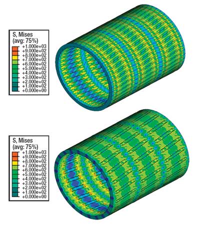 |
Fig. 3. Effective stress contours for base case design under torque loading: staggered (top) and gang (bottom).
|
|
Note that the torque values at the serviceability limit are well in excess of connection make-up torques for most premium and buttress connection designs. Therefore, limiting the torque applied during installation to the make-up torque should avoid damage to the liner during installation.
OPERATIONAL LOADS
During SAGD, the liner will be subjected to thermal-cycle loading. Liner behavior under thermal-loading will depend on the confinement condition. Two critical conditions were identified:
- Liner confined by the formation before heating-the borehole collapses around the liner before heating begins and the formation applies an initial load.
- Liner confined by the formation after heating-the horizontal borehole does not collapse around the liner and therefore does not build confining forces until some time after heating.
Under these conditions, liner confinement scenarios can vary from fully constrained to fully unconstrained, Fig. 4. Three cases represent liner constraint: (1) before heating, (2) at an intermediary point during heating and (3) some time after maximum temperature.
 |
Fig. 4. Effect of constraint conditions on the axial stress in a slotted liner.
|
|
When the liner is fully confined before heating begins, analysis indicates that the liner yields in compression at about 200°C, leading to potential liner buckling with slot opening. In contrast, if the formation confinement is imposed after heating, no compressive loading would occur, but large tensile stresses would be generated in the liner at the end of cooling, causing the liner to yield in tension. When high tension loads exist, the liner can be more vulnerable to collapse failure under the external pressure. Loading scenarios with high axial tension should be considered in the liner design.
THERMAL STRAIN AND STRAIN LOCALIZATION
Thermal strain is defined as the strain from the change in liner temperature. When a slotted liner is constrained axially by the formation, this thermal strain converts to mechanical strain in the liner by imposing an axial compressive stress. Depending on the temperature range, the thermal strain may exceed the liner material’s elastic limit, causing plastic deformation.
The analysis for this load condition uses a temperature range from 10°C to 270°C. This results in a thermal strain of 0.34%, which exceeds the elastic limit of L80 material.
Liners laterally supported by the formation. Detailed FEA for liners with staggered and gang slots suggests that under a 0.34% total thermal strain, some plastic strains develop within the slots’ tip regions with a peak inelastic strain of 0.29%. This is considered acceptable in thermal wells, since it is unlikely to cause structural or serviceability failures.
The slots tend to open under the axial compressive force caused by heating. As temperature drops later in the thermal cycle, the slots will partially close. At the end of the thermal cycle, a small amount of residual opening remains in the slots due to plastic deformation. Nonetheless, the maximum permanent slot opening for the analysis cases is less than 0.001 mm, which is well below the serviceability design limit of 0.025 mm. This suggests that thermal strain resulting from temperature change in a SAGD well will not cause structural damage or serviceability impairment to liners with the standard staggered or gang slot pattern.
Analysis for liners with overlapping slots suggests otherwise. With this pattern, the slots tend to open much sooner during the thermal cycle and they experience much larger plastic strains. For the same liner size and weight, with an overlapping slot pattern, the slot opening will exceed the design limit under thermal loading.
With any slotted liner design, as the liner yields, thermal strains may localize in weaker joints or at a joint’s weaker section. Strain localization can cause larger plastic strain in a shorter interval than the average thermal strain, leading to slotted liner damage. Strain localization factors include material strength variations, slot geometry variations, formation property variations and bending loads.
To consider strain localization effects, an axial compressive strain was gradually imposed on the liner model. The objective was to determine the axial strain capacity of the slotted liners. Figure 5 presents the relationships that were determined for slot opening versus axial strain magnitude. The slots tend to open with axial compressive strain. The analysis suggests that the overlapping slot pattern has the lowest capacity to absorb thermal strain, and it is most prone to “birdcage” buckling under SAGD conditions. The axial compressive strain capacities for the staggered and gang slot patterns are comparable. The analysis suggests that the axial strains required to cause a 0.025-mm slot opening are 0.75% for the staggered slot pattern, and 0.81% for the gang slot pattern.
 |
Fig. 5. Slot opening as a function of axial compressive strain.
|
|
Figure 6 presents contour plots of the effective stress distributions for the staggered and gang slotted liner designs under 5% axial compressive strain at 270°C. These results show the liner has buckled in the “birdcage” mode, with significant slot opening.
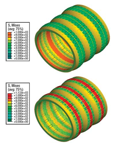 |
Fig. 6. Effective stress for the base case under 5% axial compressive strain: staggered (top) and gang (bottom).
|
|
Liners laterally unsupported by the formation. The axial loads resulting from liner thermal expansion can cause the liner to buckle. Figure 7 shows the development of liner curvature during a thermal cycle for the base case slotted liner. The lateral buckling mode starts in a single in-plane “bow” soon after the liner material yields under thermal strain. Further heating causes the buckling mode to change into a continuous series of three-dimensional “corkscrews” (helical buckle), as the liner starts to contact the borehole wall. Helical buckling is usually accompanied by high liner curvatures. In this case, a peak liner curvature of 150°/30 m can be generated by thermal loading.
 |
Fig. 7. Liner curvature due to buckling under thermal loading.
|
|
Figure 8 presents the relationship between slot opening and liner curvature based on the parametric FEA of liner bending at the peak temperature of 270°C. As shown, the slot opening develops gradually with increasing liner curvature. The critical curvatures to reach the serviceability limit (i.e. 0.025 mm slot opening) are 80°/30 m and 160°/30 m for the staggered and gang slotted liners respectively. This suggests that it is likely that a staggered slotted liner would fail as the liner buckles within the borehole under thermal loading. On the other hand, the newly developed gang slot pattern showed improved performance in resisting buckling deformations.
 |
Fig. 8. Slot opening as a function of liner curvature.
|
|
Figure 9 presents contour plots of the effective stress in the base case liner with staggered and gang slot patterns under 150°/30-m liner curvature. The staggered slotted liner shows local buckling on the compression side, leading to larger slot opening deformations. This local buckling deformation does not occur for gang slotted liners.
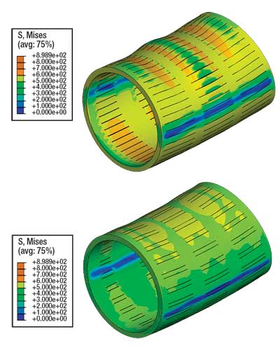 |
Fig. 9. Effective stress for base case liner under 150°/30m curvature loading: staggered (top) and gang (bottom).
|
|
EXTERNAL PRESSURE
Slotted liners are also susceptible to collapse under external formation pressure loading, since their cross-sectional stiffness is reduced by the presence of slots. The external pressure capacity is the external pressure required to cause either a slot opening/closing failure or a structural failure of the slotted liner.
The initial ovality for the liner was assumed to be 0.25% for the analyses, as is common for casing and liner products of similar size. This collapse analysis considered two different loading cases with the liner fully confined by the formation before and after heating. The analyses demonstrated that the load case with the liner confined before heating generates a lower external pressure capacity corresponding to the serviceability limit. On the other hand, the load case with the liner confined after heating results in a lower structural capacity corresponding to the collapse.
Figure 10 shows the relationship established between external pressure and liner cross-sectional ovality for the load case with the liner fully confined before heating. Note that with the liner ovalized under external pressure, some slots tend to open while others tend to close. The closing deformation condition was found to be more critical for the cases analyzed here. This analysis demonstrates that the overlapping slot pattern also has much poorer structural performance under external pressure loading. The collapse capacities for staggered and gang slot patterns are comparable. The external pressures required to reach the liner serviceability limit (i.e. 0.025 mm slot opening/closing) are 6.13 and 6.47 MPa for the staggered and gang slot patterns, respectively. The peak collapse capacities for the load case with the liner confined after heating are 12.2 and 17.5 MPa for the staggered and gang slot patterns. Note that although these two different slot patterns have similar serviceability limits, the gang slotted liner showed significantly higher structural capacity.
 |
Fig. 10. External pressure vs. liner ovality for the load case with liner fully confined before heating.
|
|
Figure 11 shows contour plots of effective stress for the staggered and gang slotted liners at the collapse condition. Note that displacements have been magnified 20 times in the plot for clarity.
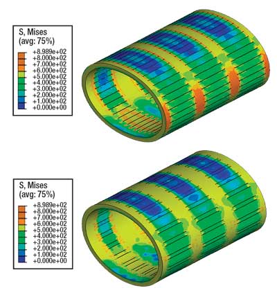 |
Fig. 11. Effective stress for base case slotted liner at collapse loading: staggered (top) and gang (bottom).
|
|
CONCLUSION
Advanced finite element models found that the overlapping slot pattern has the lowest structural capacity to absorb thermal strain and to sustain external formation pressures. Therefore, the overlapping slot pattern should not be used for SAGD wells. For the cases analyzed, staggered slot and gang slot patterns exhibited comparable structural and serviceability capacities under axial compressive strain and external pressure conditions. The gang slot pattern also had a larger installation torque-loading capacity due to a more efficient shear load transfer mechanism. In addition, the gang slot pattern significantly improves the liner’s resistance to lateral buckling and collapse pressures. 
AWKNOWLEDGEMENTS
This work was supported by C-FER Technologies and G&L Slotco. The authors acknowledge Ming Zhou of Suncor Energy for technical input to the study. Special thanks are due to Todd Zahacy of C-FER Technologies for his review of this work. This article is based on paper 2006-416, presented at the 1st World Heavy Oil Conference held in Beijing, China, November 12-15, 2006.3
LITERATURE CITED
1 Wagg, B. T. and J. Xie, Understanding the Mechanisms of Well Casing Deformations; C-FER final report to joint industry members, C-FER Project 99023, 2000.
2 Humphreys, K. J., S. C. Solanki and Link, R. A., Qualification of Grade-55 Casing for Thermal Recovery Service, C-FER final report for joint industry members, C-FER Project 88-14, 1991.
3 Xie, J., S. W. Jones, C. M. Matthews, B. T. Wagg, P. Parker and R. Ducharme, “Slotted liner design for SAGD wells,” First World Heavy Oil Conference, Beijing, China, November 12-15, 2006.
|
THE AUTHORS
|
|
Dr. Jueren Xie has over 12 years of experience in engineering research and technical consulting for the oil and gas industry. He has managed and/or played a lead technical role in numerous well completion designs for primary and thermal heavy oil operations, analysis and design of pipelines and offshore structures, and numerical analysis of steel, geomechanical structures and materials. He has authored and co-authored over 40 papers and over 70 technical reports. Xie is a principal analyst and project leader at C-FER Technologies, Canada.
|
|
| |
Simon Jones focuses on analysis projects related to sand control, connection assessment and oil sand processing equipment. His research interests include finite element analysis, vibrations and dynamics and bio-mechanics. Jones is a research engineer at C-FER Technologies, Canada.
|
|
| |
Cam Matthews has over 25 years of experience in engineering and research consulting for the oil and gas industry. He has managed numerous joint industry projects, holds four patents, has published numerous papers and is actively involved in SPE and other industry organizations. Matthews is the director of New Technology Ventures at C-FER Technologies.
|
|
| |
Brian Wagg joined C-FER Technologies in 1990 and worked for over 15 years in C-FER’s Production Technology Department on projects related to primary heavy oil operations, sand production management and heavy oil gathering systems. He is involved in design and qualification of connections and sand control for HPHT environments and risk evaluation of unplanned releases from upstream well operations. Wagg is presently manager of C-FER’s Drilling and Completions Department.
|
|
| |
Perry Parker has over 28 years of experience in drilling and completions for thermal horizontal, directional and SAGD wells. His work involves design and installation of sand control products for Oman, Venezuela, North Sea, Libya, Nigeria, USA and Canada. Parker is the president of G&L Slotco Oilfield Services Ltd.
|
|
| |
Reece Ducharme earned an applied business degree from Mount Royal College. Over the past six years he has been actively involved in marketing liner slotting and seaming technologies and services to Canadian and worldwide heavy oil industry. Ducharme is sales manager for G&L Slotco Oilfield Services Ltd.
|
|


