COMPLETIOON / STIMULATION
Dry coating resin systems applied to Adriatic gas well completions
Increasing awareness of the usefulness of dry-coated resins, when applied to proppants, should further their use in the Adriatic Sea and elsewhere.
Stephen C. Lightford, Halliburton, and Enzo Pitoni, Eni S.p.A.
Italy has numerous aging gas fields in the Adriatic Sea, producing from 100 offshore platforms. In recent years, it has been standard practice to re-enter fields and develop smaller gas pockets around existing infrastructure. Adriatic work is extensive, with four or five rigs active and an average 40 well completions per year, with more than 100 sand control operations. Outside the Gulf of Mexico and West Africa, the Adriatic is one of the world’s largest sand control areas. Completion designs are complex, mostly cased-hole and dual. Operators complete four to 10 zones in individual wells.
Adriatic gas production has featured resin dry-coating systems applied to proppants for two purposes: (1) to help halt fines migration and pore spaces plugging; and (2) to prevent sand production. Success of these coatings has effectively increased gas reserves from gravel pack workovers and new completions.
By applying two types of resin dry-coating systems to failed sand control completions, these systems have shown their potential to effect changes to Adriatic completion designs, and offered the possibility of gaining reserves from formation intervals that have suffered from excessive fines. There are large gas reserves not yet fully exploited because of fines, and surface modification agent (SMA) technology offers a solution.
Since the original work, SMA has been tested in a new well completion, in a five-well drilling campaign. In a fines-producing layer, the SMA-treated well was the only one in the field that did not suffer from fines production. Eni now plans to re-enter an Adriatic field with workover rigs to apply SMA technology, to prevent the early production loss that has discouraged field development.
A liquid resin system (LRS) was used to repair a failed screen. It allowed the treated well to produce sand-free without the need for an inner screen. The success of LRS technology opens up the possibility that a screen-less completion may be a primary completion method, even in depleted, loose, dirty sands. With the recent introduction of a new biopolymer gelling system, there is an opportunity to reduce completion costs, when completing intervals in 5-in. liner sections.
GEOLOGY
Reservoir lithology consists of Pliocene alluvial sands, turbiditic deposits that were laid down by the Po River. Gas field depth varies from 800 m (2,625 ft) TVD to over 3,500 m (11,483 ft) TVD. These sands are clay-like, highly plastic and interbedded with stronger shale bands that separate the main layers. Interval height varies from 2-30 m, with gas permeability ranging from 5-500 md. Pore pressure gradients also vary widely, from overpressurized sand with 1.6 sg to partially-depleted structures as low as 0.2 sg. As the fields’ main areas become depleted, new completions are sidetracked into smaller, less-depleted sand lenses. These structures have high silt and lower-quality sands. In most parts of the world, these offshore gas deposits would not be commercially viable.
SAND CONTROL HISTORY
Sand control has been necessary in Adriatic gas fields since the first wells went onstream. Initially, the best option was conventional, low-density openhole gravel pack. With pressure depletion, and as reservoirs became more complex, cased-hole completions were necessary to isolate layers, to prevent water production and to fully deplete layers, Fig. 1.
 |
Fig. 1. Typical Adriatic Sea well completion, offshore Italy.
|
|
|
In these clay formations, cased-hole gravel packs were installed with limited success. In 1995, the frac-pack technique was first applied to reduce the gravel pack skin effect. These treatments used brine or a linear gel system.1 Gel technology has improved in recent years, and frac packs are now performed using viscoelastic gel systems2 that use sand concentrations greater than 12 lb/gal. A significant difference in fracturing practice in Adriatic gas sands has been using low-efficiency fracturing fluids. Adriatic sands are highly plastic formations that are easily fractured at very low pump rates. Therefore, to prevent the fracture from propagating out of the layer, the fluid viscosity, leak-off rate, and pump rate need to be carefully controlled. The process has become highly refined.3
DESIGN PHILOSOPHY
Since the mid-1990s, about 1,000-plus frac-pack operations have been run. The objective of Adriatic frac-pack treatments is to place a fracture, 10 m to 20 m long, into the formation to reduce skin damage in the near-wellbore. Optimization follows these objectives:
• Placing 750-1,000 kg/m inside the fractured pay zone
• Tip screen-out design for maximum fracture conductivity
• Size 60/40- or 30/50-mesh gravel/proppant
• Fracture height growth over the full pay zone
• Fracture length, so that fracture height does not propagate out of zone.
A pseudo-3D fracture simulator is used to design fracture geometry, based on elastic mechanical rock properties. The simulator has proved accurate for optimizing treatment for these short, wide fractures. Confidence in model predictions is based on matching net fracture pressure with production results from an extensive Adriatic database.
FLUID SYSTEMS
Because of the nature of Adriatic gas reservoirs, it has been necessary to use unconventional fracturing fluid technology to achieve the desired hydraulic fracture geometry. To achieve a tip screen-out in these soft plastic formations (Young’s modulus as low as 50,000 kg/cm2) of low-permeability sand, 10-30 md or even less for gas (2-6 md permeability to water), it is necessary to use a fracturing fluid with high formation-leakoff characteristics. Using this type of fluid is beneficial for the following reasons:
• Fluid leaks into the pore space around the fracture face, resulting in less crushing of the pore spaces and less loss of permeability.
• High leakoff is required to achieve the tip screen-out, as these formations are very easily fractured.
If reservoir damage was the only consideration, brine would be the optimal fluid to fracture these formations.4 However, its viscosity has proved to be too low to carry proppant through perforations at the high concentration (8-12 lb/gal) required to produce minimally acceptable fracture conductivity. Linear gels (hydroxyethyl cellulose) were used widely until 2000, but these could not carry higher sand concentrations at acceptable polymer loading. Some work was also done with cross-linked gels, but this caused excessive fracture height growth and no tip screen-outs.
Linear gels have been replaced by viscoelastic fluids, i.e. high shear-thinning fluids. These fluids replaced linear gel systems, because they offer improved sand-carrying capacity and high leakoff properties. In addition, laboratory testing on Adriatic formation cores indicated that the fluids do not damage the formation.2,3,5,6 The high leakoff of viscoelastic fluid resulted in fracture-fluid efficiencies of less than 40%, even in lower-permeability formations; hence, tip screen-outs can be achieved.
Initially, viscoelastic fluids used in the Adriatic were surfactant-based, but, more recently, biopolymer-based viscoelastic fluids have been introduced. Biopolymers have advantages over the surfactant-based fluid systems. They contain internal breaker systems. In gas wells, they eliminate the need to pump hazardous alcohol or hydrocarbon pre-flushes or over-flushes to break the gel viscosity, and/or they eliminate surfactant adsorption to the rock, needed to reduce/eliminate residual fluid damage. The first biopolymer was a liquid-gel concentrate (LGC); these products are highly concentrated forms of the fully hydrated gel prepared in a manufacturing plant. To prepare the fracturing fluid, one dilutes the product with water. The advantage of using LGC is that it is easily mixed on location, which precludes such problems as formation of “fish eyes” that require filtering of the prepared gel to prevent formation damage. One disadvantage to the process is that LGC requires large amounts of storage space.
Technology frequently moves in circles in the industry. A few years ago, the industry was moving away from mixing powdered products, but recent developments in polymer manufacturing are moving us back to powders. In this case, the original LGC biopolymer has been replaced by a different, powdered biopolymer that, with less drum handling, is easier to prepare than LGC. This particular biopolymer can be mixed in low-shear conditions with no risk of the generation of micro fish eyes. Therefore, there is no need for high-pressure shear devices or filtering following mixing.
COATING TECHNIQUES
When discussing coated proppant, most people would think of resin-coated proppant (RCP) that is already coated before leaving the manufacturing plant. Since the early 1990s, there have been products introduced that continuously coat the proppant, while it is pumped into the well to replace the pre-coated resin. There are two ways of placing the coating on the proppant. The first method is termed “wet coating.” In wet coating, the coating agent is added to the fracturing carrier fluid, then the proppant is added. Both the carrier fluid and coating agent are in competition to wet the proppant. If the balance is not correct, this can lead to two problems:
• Excess coating chemicals in carrier fluid are pumped into the well, possibly causing formation damage.
• Less coating agent is placed on the proppant as it is replaced by the gel, and/or poorer-than-predicted performance properties are achieved.
In addition, the coating agent may strongly affect carrier fluid properties.
To avoid these problems, a dry-coating process has been developed. In this technique, the coating agent is applied to the proppant during transfer from the storage silo into the carrier fluid, as it is being pumped into the well. Before the addition of the proppant to the carrier fluid, the coating is complete. Therefore, the gel cannot compete to coat the proppant, because the coating is already in place. This leads to more consistent properties from the coating agent and helps eliminate the possibility that an excessive amount of coating agent is carried in the well. While these coating agents can still affect the breaker and cross-linker performance, the effects are far less severe than in the “wet coating” process. There are two particular coating agents that have a wide application in the Adriatic: Surface-modification agents (SMAs) and liquid-resin systems (LRS’s).
SMA TECHNOLOGY
A specific SMA has been used widely, particularly in the Gulf of Mexico. Adoption in the Adriatic has been somewhat slower and is still in its infancy. An SMA is a thermally stable, polymeric material that coats the proppant during well treatments.7 Stress on the fracture face and proppant changes occur during well production because of variations in gas output rates. Further stress changes can also occur at the onset of water production, which causes a change in capillary pressure. These stresses weaken the formation matrix and may cause the formation to yield, resulting in fines invasion into the proppant or gravel pack.
Enlargement of hole diameters in water wells was used as a sand-control technique before the oil industry began. Modern frac-pack techniques vary this practice. Frac packs create a highly conductive fluid channel that will reduce near-wellbore reservoir flow velocities and stresses. This can reduce fines migration. SMA technology improves the technique several ways when applied to certain Adriatic formations. SMA permits larger gravel/proppant sizing, increasing the fracture’s conductivity to further support the reduction in near-wellbore velocities, thus reducing the forces to move the formation materials. Using SMA also helps prevent formation fines from entering the conductive fracture, which over the well’s life, would plug the fracture conductivity.
Selecting a gravel/proppant pack size is often based on a rule, such as five or six times the median formation diameter in relatively homogeneous sand formations that follow a normal distribution pattern.8 However, correct proppant pack sizing becomes particularly difficult, when the formation-size distribution is highly heterogeneous, with authigenic clay particles, a condition typical of the Adriatic’s geologically young sediments. Previous work has shown that using an SMA coating allows a median diameter ratio of up to 20:1.7 This ratio has a dramatic impact, if this new sizing criterion occurs when proppant is sized for very fine-grained, poorly consolidated formations. When the 6:1 proppant-sizing criterion is used, proppant/gravel sizes as fine as 100/120 US mesh will result. While proppant of this size can theoretically combat fines migration, it would greatly reduce fracture or gravel-pack conductivity. However, new sizing criteria for surface-modified (sticky surface) proppant will allow 30/50-mesh proppant to be used to control fines invasion.
SMA functions, because it remains sticky, and like insects on sticky “fly paper,” smaller particles or fines adhere to the treated material surface, allowing a layer of fines one particle deep to be deposited on the surface at the proppant/formation interface, Fig. 2. Consequently, pore-throat size is reduced, and particles are prevented from invading the pack and plugging the conductivity. It is incorrect to say that this technology applies to all Adriatic areas. However solving this fines migration problem is critical to certain field developments or to certain of the marginal, more silt-like intervals. To prove whether this technology could solve fines migration, it was tested on a well that had lost production because of fines-migration problems.
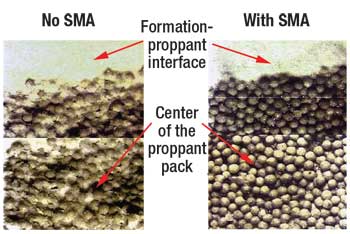 |
Fig. 2. Formation/proppant interface: Single layer.
|
|
TREATING A FAILED GRAVEL PACK
The well selected is in a field that was discovered in 1981 and placed into production in 1992. All of the platform’s seven wells are dual completions, with four to six layers typically completed. Most have been gravel-packed. In the treated well’s long string, two layers are completed. The upper level was not gravel packed. In the lower level, the treated interval was completed with conventional gravel pack using 50/70 gravel and 0.8-micron screens. The completion design was dual with 2 3/8-in. tubing. The lower level was treated, because it had full access for coiled tubing, Fig. 3. The other zone was abandoned.
 |
Fig. 3. Schematic for well, where SMA was applied.
|
|
Initial production was 75 m3/d (512 bopd), but after 9 months, it was necessary to decrease draw down formation pressure, to prevent production of fines of 0.6 to 20 µm size at surface. There was clear evidence of fines plugging the gravel pack and increasing the skin in the completion, a phenomenon quickly compounded by arrival of some formation water. Eventually, a gas-hydrate plug formed in the completion tubing at the seabed, and production stopped.
Similar output losses occurred in most intervals produced in this field. Gravel pack repair with a rig-less workover was proposed, as was placing the well on a long-term production test. The solution proposed was to fracture the well through the existing completion using SMA on the proppant. To perform the fracture treatment, it was necessary to perforate the existing screen. SMA does not set, so it could not be relied upon to hold proppant in place. Therefore, after fracturing, a screen was placed through the 23/8-in. completion. A description of the workover follows.
Wellbore preparation. The layer was isolated, tubing was cleaned using acid, and an injection test was performed. This test was necessary to determine whether the screen required plugging with a sealant before fracturing. An interesting consideration was the intent to fracture a well that had been gravel-packed through the existing perforated screen. There was concern that because of poor entry-fluid conditions to the fracture, the operation would terminate early because of near-wellbore sand-out. To avoid this problem, the existing completion was sealed. A sodium silicate sealant was used.
Perforation of screens. The perforation process caused major concerns, due to the risk of getting the gun stuck in the hole. These operations did not go as planned (the lower part of the screen collapsed), but fracturing proceeded, even though only a 1-m interval from 3,374 to 3,375 m MD had been perforated.
Fracture treatment. Layer data are in Table 1. Only 1 m of perforations was open for fracturing, but this did not compromise the fracture design’s objective, to create a fracture of about 30 m long and 10 m high. SMA had been selected to minimize or prevent fines movement into the wellbore. The sieve analysis of formation fines, as recovered at surface, indicated a very small particle size, with 90% between 0.6 and 20 microns. SMA was used primarily to prevent these particles from entering the fracture proppant bed as previously described.
TABLE 1. Formation properties, well treated
with SMA coating |
 |
|
| TABLE 2. SMA case study |
 |
|
Treatment was to be performed with standard fracturing equipment, with the exception of equipment for coating proppant with SMA. The produced fracture profile is shown in Fig. 4. Proppant was cleaned from the wellbore by circulating 3% KCl brine, using 1¼-in. coiled tubing with standard jetting nozzles. The 1¾-in. screen was then run into the well and across the perforations.
 |
Fig. 4. Fracture dimensions, SMA technology.
|
|
To bring the well onstream, lifting operations, down to 3,000 m MD, were repeated over several days, but they failed to re-establish output. In a final attempt to recover the well, the string was pressurized with nitrogen that was injected into the formation. Subsequent lifting brought the well into production. It was put into the flowline with 53 kg/cm2 (754 psi) of pressure at the wellhead, and it produced 12,000 m3/d (about 425,000 cfd) of gas. This was a low rate compared to expectations, but it was acceptable, since only 1 m of formation was open to flow.
Production following treatment stabilized at 21,000 m3/d (about 742,000 cfd) of gas. The well showed no hint of any damaging phenomena occurring downhole, despite only 1 m of perforations and a very small screen further restricting flow. Production was maintained for 18 months, until the well was shut-in for other platform workovers.
LIQUID RESIN SYSTEMS
LRS proppant-coating is becoming more widely adopted and may develop into screen-less completion technology, as proved by this well’s remedial work.
Adriatic reservoir temperatures are abnormally low, typically varying from 35° to 50°C, close to summer ambient temperatures. Conventional resin-coated proppants (RCPs) are coated at the manufacturer before transport to a well site. RCPs are generally activated by a temperature/pressure combination. For low-reservoir temperatures, RCP would be activated while in storage, and the material set before pumping. Some RCP formulations can be activated at low-reservoir temperatures. However, these products are activated by pumping chemical flushes after treatment. This takes additional time. There is no guarantee that the activator will contact all RCP.
LRS coatings are applied to the proppant, on-site, immediately before pumping into the well. So, there is no concern that the coating will set during storage. At low temperatures (below 225°F), the liquid coating consists of a resin and an activator. These components are mixed as the coating is applied to the proppant. Application is achieved by injecting the resins and activator into an inline mixer using electronic liquid-additive pumps, then spraying the product onto dry proppant. Setting time starts from when the components are mixed. Downhole, the coating sets in several hours.
LRS coatings can achieve consolidation strengths much higher than conventionally cured, resin-coated proppants,9 even at low temperature, and when very low or zero confining stress is present. This higher strength is possible, because the LRS-treated proppant is initially “tacky,” which promotes grain-to-grain contact. In contrast, the RCPs, even when heated, are not as tacky and have little grain-to-grain contact, if no stress is applied. Due to this tackiness, capillary action causes the liquid resin to flow, concentrating it between proppant grains and resulting in greater resin concentration at contact points, where it is needed to improve the strength. A further LRS advantage is that it is not removed from the proppant surface during pumping, because the resin system has been specially formulated to coat proppants preferentially. By contrast, RCP can be eroded during pumping, compromising the cured pack’s final compressive strength.
For these reasons, LRS properties are better-suited than conventional RCP to Adriatic sand control. Because they do not require confining stress to obtain high compressive strength, they offer a realistic chance to do screen-less completions on new wells. This is supported by a field trial, with a successful repair to a failed gravel pack completion.
FLUID COMPATIBILITY
There are compatibility issues with RCP and LRS systems. When combined with fracturing fluid, break time or other properties may change. In addition, bonding strength on LRS coating systems can be affected. It is important that quality-control tests are performed to determine this effect. These procedures are well-established and involve mixing the fluids with the coated proppant in the laboratory and observing changes. As regards fracturing fluid, this observation would generally be to check for changes in viscosity and break time following contamination. For proppant, it would be a change in compressive strength.
Tests showed that intermediate-strength proppant coated with LRS, which had been contacted by the gel and breaker solution, had an unconfined, average compressive strength of 998 psi after 24 hr. In general, unconfined compressive strength above 100 psi is adequate for high gas flowrates.10
Breaker tests with the contaminated liquid biopolymer were not so successful. After extensive lab testing, a combination of breakers that would function successfully could not be found. Low Adriatic reservoir temperatures (35° to 50°C) are a particular challenge to finding breakers that can function. However, researchers proceeded with the field trial, knowing that the well might recover slowly. Internal breaker problems would be circumvented by using a strong, oxidizing pre-flush with a contingency plan of using an after-flush, if the well failed to flow.
A recent change from the liquid biopolymer to a different dry-powdered biopolymer, and further extensive laboratory testing of the internal breaker and LRS coating system, have furthered development, so that both systems are fully compatible with Adriatic conditions. This should encourage further work.
REPAIR WITH LRS
The well was a dual completion, with the lowermost section inside a perforated, 5-in. liner (Fig. 5). On completion, the well was fractured with 15 t of 30/50-mesh, intermediate-strength proppant without a resulting tip screen-out. Afterwards, a 2 3/8-in. premium screen was run, and a gravel pack was installed. After 18 months, the screen failed inside the liner, and the well produced back all the proppant, plus formation sand, before the interval was closed. Dry gas reserves were significant enough to attempt a repair, despite the complexity.
 |
Fig. 5. Case Study 2: well schematic.
|
|
The screen was repaired by pumping a frac pack with a tip screen-out design through the hole in the screen. Before treatment, injection tests were performed to ensure proppant injection through the hole. Once this path was established, a fracturing job similar in size to that performed on the original completion was run. To prevent production of sand and/or proppant, the proppant was coated with LRS. To ensure that this proppant remained close to the wellbore, the treatment was under-displaced, leaving proppant in the tubing. At the end of April 2007, the well was still producing an average 49,000 sm3/d (1.73 MMscfgd) without any sign of proppant or sand at the surface.
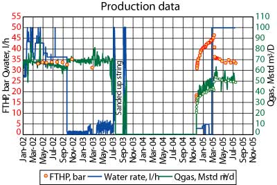 |
Fig. 6. Case Study 2: production data.
|
|
After leaving the well static overnight for the LRS to set, coiled tubing was used to clean out the well to the bottom of the existing completion, i.e. through the failed screen. The well was then brought onstream by nitrogen lifting. Once it was cleaned, it was connected to the flowline, through a cyclone desander mounted online. During initial production, a few proppant grains were trapped, but since then, the well has flowed sand-free. Production data are in Fig. 6. By re-establishing sand-free output in these plastic, clay sands, the treatment was a success, and the return on investment was rapid. 
LITERATURE CITED
1 R. Maroli, G. Ripa, G. Menilli and D. McCulloch, “Development of frac-and-pack techniques in a multi-layer reservoir, offshore Italy,” SPE paper 36900, SPE European Petroleum Conference, Milan, Italy, Oct. 22-24, 1996.
2 S. Cobianco, E. Pitoni, G. Ripa, D. Perez, M. Patey and J. Jeanpert, “Continuous improvement in fracturing fluid design in gas fields of the Italian Adriatic Sea region,” SPE paper 94465, SPE European Formation Damage Conference, Sheveningen, The Netherlands, May 25-27, 2005.
3 S. P. Mathis, E. Pitoni, G. Ripa, G. Ferrara, A. Conte and M. Ruzic, “VES fluid allows minimized pad volumes and viscosity to optimize frac-pack geometry: Completion type evolution in Barbara field, Central Adriatic,” SPE paper 78317, SPE European Petroleum Conference, Aberdeen, Oct. 29-31, 2002.
4 L. Capra, G. Ripa, G. Ferrara and R. Travis, “Field experiences and guidelines for using non-viscosified fluids in frac-pack operations,” SPE paper 36945, SPE European Petroleum Conference, Milan, Italy, Oct. 22-24, 1998.
5 N. Heitmann, E. Pitoni, G. Ripa and K. England, “Fiber-enhanced visco-elastic surfactant fracturing enables cost-effective screen-less sand control,” SPE paper 78323, SPE European Petroleum Conference, Aberdeen, Oct. 29-31, 2002.
6 E. Pitoni, F. Devia, S. G. James and N. Heitmann, “Screen-less completions: Cost-effective sand control in the Adriatic Sea,” SPE paper 58787, SPE International Symposium on Formation Damage Control, Lafayette, Louisiana, Feb. 23-24, 2000.
7 J. Weaver, M. Blauch, M. Parker and B. Todd, “Investigation of proppant-pack/formation interface and relationship to particulate invasion,” SPE paper 54771, SPE European Formation Damage Conference, The Hague, May 31-June 1, 1999.
8 M. Blauch, J. Weaver, M. Parker, B. Todd and M. Glover, “New insights into proppant-pack damage due to infiltration of formation fines,” SPE paper 56833, SPE Annual Technical Conference and Exhibition, Houston, Oct. 3-6, 1999.
9 P. D. Nguyen, J. D. Weaver, M. Parker, M. McCabe, M. Hoogteijling and M. J. van der Horst, “A novel approach for enhancing proppant consolidation: Laboratory testing and field applications,” SPE paper 77748, SPE Annual Technical Conference and Exhibition, San Antonio, Texas, Sept. 29-Oct. 2, 2002.
10 P. D. Nguyen, R. G. Dusterhoft, B. T. Dewprashad and J. D. Weaver, “New guidelines for applying curable resin-coated proppants,” SPE paper 39582, SPE Formation Damage Control Conference, Lafayette, Louisiana, Feb. 18-19, 1998.
|
THE AUTHORS
|
|
Stephen Lightford has worked for Halliburton Services for 25 years in the Middle East, Africa, the North Sea and Europe. He now works in Moscow as technical manager for Russian operations, and is primarily involved in production enhancement operations. Before this assignment, he led a small group of engineers involved in Halliburton’s sand control and well stimulation projects in Italy. Mr. Lightford holds a BS degree in mechanical engineering.
|
|
| |
Enzo Pitoni is project team leader for production optimization in ENI’s Italian District, responsible for developing innovative solutions to improve production from existing or newly developed fields. His expertise includes stimulation, water shut-off, and sand control. Previously, he worked as global advisor for production optimization, based in Milan, and was involved in both Italian and international operations. He has also worked in Tunisia and the Middle East. Mr. Pitoni holds a PhD degree in chemistry from Perugia University, Italy, where he began his career working in the research department.
|
|

