WELL CONTROL AND INTERVENTION
Controlling the Well 23 blowout
in Iran's Kangan field
An earthquake had shifted a shallow fault, damaging casing
and causing the blowout.
Neal Adams, Neal Adams Firefighters, Inc., Houston;
Mehran Makvandi, National Iranian Drilling Company
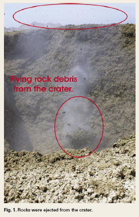
Iran's Western Zagross Production Company reported a sudden, substantial production decrease from Well 23 on 9 October 2005. A well-site inspection indicated the well had blown out underground, channeled to surface and was creating a large crater near the wellhead. The high flowrate was blowing rock debris out of the 50-m deep crater, Fig. 1. The shallow nature of the well, subsequent cratering and fire required five different well paths to establish sufficient connectivity, and an all-out pumping assult to control the well.
BACKGROUND
Kangan field is the second largest Iranian gas and condensate producer, ranking just behind the huge Fars field. Kangan reservoir is part of the expansive Khuff zone of fractured limestone reaching west as part of Qatar�s North Gas field and east into Iran. The well is 20 km north of Kangan City in the Zagross foothills of Fars Province.
Kangan field has 20 wells that produce about 2.5 Bcfd (70 MMm3/d) of gas and 20,000 bopd. Well 23 was producing 88 MMcfd (2.5 MMm3/d) and 750 bpd of condensate. The flowing tubing pressure was 1,900 psi from a bottomhole reservoir pressure of 2,700 psi. Reservoir dimensions are 200-m thick, 8-km wide and 65-km long.
CONTROLLING THE WELL
After the event was reported, the National Iranian Oil Company (NIOC) dispatched its operational groups to the site. Wireline tools were rigged and run on the well to perform an initial assessment of downhole damage. The results indicated substantial casing damage at 66 m below surface.
The initial plan.
It was concluded that it would not be possible to attempt a re-entry of the well as a direct means to control it. Steps were taken to spray water on the existing wellhead in an effort to secure it for possible future access.
NIOC contacted a western blowout specialty company for assistance. A cost estimate was requested. After evaluating the cost estimate, NIOC determined the amount exceeded budget limits imposed on the company. NIOC was forced to pursue kill operations independent of expertise obtained outside Iran.The Iran Oil Central Areas group requested advice and assistance from the National Iranian Drilling Company (NIDC). Common discuss-and-development sessions were conducted. The groups made the decision to drill two relief wells on either side of Well 23, Fig. 2.
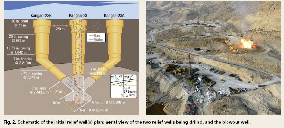
Implementing the plan. Rig 82 was completing a well in Homa Gas field. When finished, it was moved to Kangan in February 2006. The relief well site for Rig 82 was at a 220-m displacement from the Well 23 site. After three months of drilling under difficult
conditions, the Kangan Well 23-B relief well was directionally drilled to 2,500 m. The second relief well, Kangan Well 23-A, was spudded with Rig 42, about 300 m from the blowout well.
For drilling the two directional wells, the group built six water ponds with a total volume
of 70,000 bbl. Two water supply lines, each 25 km, were constructed from the Persian Sea to the site. Flow capacity through the lines was 800 bbl/hr. Also, 20 frac tanks, each with a 300-bbl/hr capacity, were mobilized and set up.
The strategy for the blowout control operations was based on direct access of the relief well to openhole below the blowout well. Kill fluids such as water or drilling fluids would be pumped at high rates to kill the flow from the producing reservoir.
According to the plan, the relief well hole size was to be 6.125 in. and was to be drilled at a 60� angle to 2,500 m.
Injection operations started by pumping water and a high-viscosity pill, with flowrates of 10�40 bbl/min. Blowout effluent at the crater near the Well 23 wellhead was monitored to assess success. Water and part of the high-viscosity was observed in the crater, which indicated an initial connection path from Well 23-B to Well 23 had been established. However, the flow path was not sufficient to kill the flow with just water and drilling fluids.
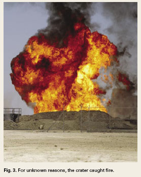
As time progressed, the surrounding surface fractures began to increase in size. Rocks and formation debris were being blown from the crater, Fig. 1. Gas flow increased. A flash fire was observed at 19:15 hours on 3 June 2006. Gas flowing from the crater, at a 150-m distance from Well 23, ignited. Also, the wellhead ignited, Fig. 3.
A new plan. The lack of success of the initial kill attempt led to the formation of a special well control group, developed from internal NIDC organizations. The group was mobilized to the site on 4 June 2006. Responsibility for well control operations were transferred from NIOC to NIDC at this point.
The new plan was to drill some search and kill legs off of the main hole, on different angles, to identify an improved path to increase connection with Well 23. These holes were drilled as follows:
Leg 1: Main hole at angle 33�, azimuth 60�
Leg 2: Turn to right and drop angle to 0�
Leg 3: Turn to left and drop to 8� and then build to 46�
Leg 4: Drop angle to 2� and build to 50�
Leg 5: Building angle to 85� with the target at angle 85� and azimuth 65�
After three of the directional legs were drilled on different sides of the hole under the Well 23, injectivity operations were conducted to determine if a sufficient path had been established to kill the flow. Pump rates of 30�60 bbl/min. were used and 11,000 bbl were pumped with pressures up to 2,300 psi. The effort did not kill the flow. The decision was made to plug all drilled holes with cement. After evaluating operations, Leg 5 was planned and drilled, as described above.
After Leg 5 was drilled, an injectivity test was conducted. It was determined that an improvement had been achieved in connectivity with the Well 23 borehole. To further improve this connectivity, a 15,000-bbl volume of 20% HCl with retarder was pumped. Another injectivity test was conducted showing that connectivity was improved by the procedure. Another acid job of 42,000 bbl with retarders was pumped. After the acid job, high viscosity pills and water were pumped periodically at flowrates of 5�10 bpm over a 20-hour period.
After monitoring the well fire and observing an increase of water returning through the flare line (3.5 liters/min.), a decision was made to do a maximum power kill operation through Well 23-B. The pump trucks, frac units, blenders, manifolds and water tanks were linked together. All high pressure lines were tested to 5,000 psi. Also drilling mud pumps were included with the other kill equipment to increase the pump rate capability.
Kill operations started at 09:30 hrs on 28 June 2006. This operation used 14 high-pressure pumps to achieve a rate of 90�120 bpm. An 11,000-bbl volume was pumped. The well flow was stopped by 11:00 hrs. The wells were secured with cement and subsequently abandoned.
EPILOG
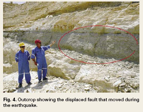
Much later, information became available that showed an earthquake had occurred near the time of the blowout. The quake�s epicenter was located in the vicinity of the well. After assessing this information and reviewing the shallow geology, it was determined that the earthquake had caused a shallow fault to shift. It appears that the fault damaged the casing at 66 m. The earthquake and moving fault did not appear to have affected other field wells. Figure 4 shows the fault outcrop near the well site. 
|
THE AUTHOR
|
 |
Neal Adams has over 30 years of oil industry experience as a firefighter, blowout control specialist, engineer and consultant. He earned a BA (honors) from Northeast Louisiana University in 1971, and an MS in petroleum engineering from the University of Houston. Adams has traveled to and worked in 35 countries including all the oil producing regions, and was instrumental in extinguishing fires in the 1991 war with Iraq. He is the author of five books, 60 journal publications and numerous technical research reports. Adams is President of Neal Adams Services, Houston (www.NealAdamsServices.com).
|
| |
Mehran Makvandi is the onshore operations drilling director, District-1, for National Iranian Drilling Co., which he joined in 1990. Mehran has a first petroleum engineer degree from Aghajari Azad Islami University and a second applied drilling engineering degree from NIDC College. He supervises 23 land rigs working in exploration, development and workover in Iran.
|
|
|

