DEEPWATER TECHNOLOGY
Alternative well control methods for deepwater dual density drilling
Better openhole pressure distribution favors the gas-lift, dual density method.
Mikolaj Stanislawek, ENSCO Offshore Co. and John R. Smith, Louisiana State Universityr
Deepwater resources are expected to be a major contributor to future oil and gas production worldwide. Deepwater
Gulf of Mexico resources are especially important for suppressing US production decline. However, a narrow margin between formation pore pressure and Fracture Pressure (FP) exists in many over-pressured basins, including
the GOM. This limited margin often becomes narrower with increasing water depth due to reduced overburden pressure and shallow abnormal pressure. For deepwater wells, reaching the target depth, while retaining a useable borehole size, is often difficult.
Deepwater resource development is often limited by high capital costs. Dual-gradient drilling methods1�10 have been proposed to retain a useable borehole size and provide simpler, safer, more economicwell designs that could increase deepwater gas development and use. The authors studied a dual density drilling concept using riser gas-lift7, 8, 9 to implement a dual-gradient system.
The new system would provide a simpler, more economic design using nitrogen and mud with the density of seawater in the riser annulus and normal mud density in the wellbore. In concept, it would utilize more standard equipment than the separate industry projects1�7, 10 using seafloor pumps. The system�s advantages would be fewer casing strings, larger mud-weight margins and larger production casing for a higher production rate. Smith,14 Lopes,9 Maus15 and Herrmann7 discussed some aspects of well control with a riser gas-lift system. In addition, a number of well control studies have been done for a dual-gradient system, based on use of a mudlift pump, including those by Choe11, 12 and Schubert.12,13
No tests, simulations or comprehensive study using a riser gas-lift system have been done for well control. The simulations below are the first study of well control for a riser gas-lift system.
PROBLEM
The major question addressed was whether effective well control can be applied to a system with many different fluid
densities, continuous multiphase flow, and relatively complex flow paths. First, it must be determined if it is feasibile to reach dual density operating conditions with a gas-lift system. To do this, the riser�s bottom pressure must equal seawater hydrostatic pressure at the mud flowrates and densities used in drilling. Since returns could be taken through the choke line after a kick, the line�s bottom pressure should also equal seawater hydrostatic pressure during kick circulation. It is important to consider the emergency case, when mud pumps and nitrogen injection fail potentially causing riser collapse.
The study addressed three critical well control phases: kick detection, inflow stoppage and circulation. Each of these was simulated using a transient, multiphase numerical simulator. The plan was to analyze alternative approaches for gas- and saltwater-kick control to determine the best well control method: conventional circulation against a surface choke, a dynamic approach using dense fluids in the well to regain overbalance, use of a subsea choke or some combination of techniques.
The criteria used included: maintaining the bottom hole pressure above FP, BHP variation magnitude, fracturing risk, choke adjustment responsiveness, choke operation difficulty and process complications or difficulties. Regaining well overbalance after kick circulation must also be considered. In each case, well control operations with the dual density, gas-lift system should be compared against conventional, single density well control.
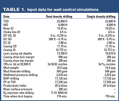
The cases in this study represent a deepwater well in 6,000 ft of water, based on actual GOM well designs, Table 1. They assumed relatively high, well productivity, based on two points: 1) the reservoirs drilled must be high productivity to be economic and 2) a high productivity formation is more difficult to control and is a rigorous test of alternative
well control methods. The well description and conditions were revised slightly during the course of this study to be more complete and more realistic.
The simulations assume the use of a Drill String Valve (DSV) to arrest the U-tube effect, which occurs when the drillstring fluid density is greater than the riser�s average fluid density.12 The DSV is placed in the drillstring near the bit to support the excess hydrostatic pressure of the full mud column in the drillstring when the rig pumps are shut off.
Simulation was chosen to investigate well control because different equipment arrangements and operating strategies can be assessed and compared to conventional operations without conducting full-scale experiments. Evaluation was based on results from simulation of a transient, full-scale well experiment by Lopes.9 The results gave confidence that a transient, multiphase numerical simulator will provide relevant predictions for transient, well control scenarios. The full-scale experiment was conducted in a relatively large 9.625 in. by 3.5 in. annulus, riser annulus conditions of most interest in this study.
PROBLEM
For the dual density, gas-lift system to be effective, riser bottom pressure must equal the seawater hydrostatic pressure at the mudline. In addition, the same pressure must be achieved at the base of the choke line during well control operations with riser gas-lift. Achieving dual density conditions was confirmed by simulating a 5,000-ft, 19.25-in.-ID riser with 5-in.-OD drill pipe inside. Various rates of 16 ppg mud and nitrogen were used, Fig. 1.
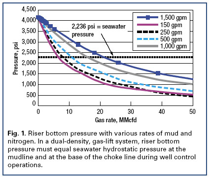
The bottom pressure in the riser annulus at the mudline can be successfully lowered to the desired seawater hydrostatic pressure and even further. The riser circulation system with gas injection operates in a hydrostatic-dominated mode; the riser�s large ID limits the friction effects. This makes controlling the wellhead pressure straightforward as pressure is constantly decreased for an increased gas rate.
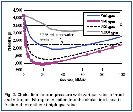
Dual density conditions can be achieved at mud circulation rates up to 1,500 gpm. Dual density conditions must be maintained during well control operations, as well as during drilling operations. Given that returns must normally be taken through a choke line during well control operations, nitrogen injection into the base of the choke line was investigated. Several scenarios were simulated. The simulated case consisted of 5,000-ft choke line with 5-in. ID. Various rates of 16 ppg mud and nitrogen were used, Fig. 2. A friction-dominated mode, where the pressure at the choke line inlet increases with increasing gas rate, is evident at high gas rates. The choke line�s small diameter causes friction effects to be more important. For high mud flow rates, it is impossible to decrease pressure to the desired value, because friction pressure losses dominate. Nevertheless, operating the choke line in the friction-dominated mode may be helpful while circulating kicks out of the well, so that small gas injection rate changes or gas circulated from the well will not have a large impact on the bottom pressure.
KICK DETECTION
Early kick detection minimizes kick size and decreases the difficulty of safely controlling the kick. For deepwater operations and dual density drilling, kick detection is complicated by rig motion and multiphase flow in the riser.
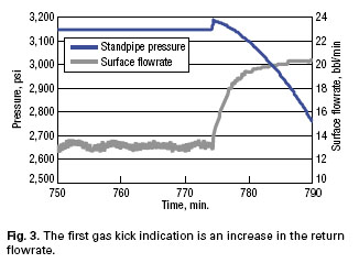
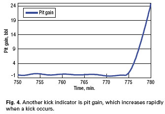
Simulation helped identify the most reliable kick indicators. Well conditions are described in Table 1. The indicators monitored during the simulation were liquid flow rate out, pit level, Stand Pipe Pressure (SPP), wellhead pressure, and BHP. After simulating 774 min. of dual density drilling, a gas kick enters the well with 17,320 psi and a Productivity Index (PI) of 25 b/d/psi. The first indication of a gas kick entering the well bore is an increase in the return flowrate, Fig. 3.
Another potential kick indicator, pit gain, increases with time, Fig. 4. Its usefulness increases with time as the gain increases and the indication becomes more conclusive.
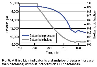
A third indication is a SPP increase of about 50 psi in 1 min., then a SPP decrease caused by hydrostatic pressure loss in the annulus as the gas volume increases.
The initial pressure peak is from gas entering the well annulus and �pushing� mud ahead of it, causing additional annularfriction. Over time, hydrostatic effects dominate and BHP decreases significantly, Fig. 5. These pressure changes only become conclusive when the pressure decrease is large and are likely to be a slower indicator than flowrate out or pit gain.
Conventional operations often use a �flow check� procedure to confirm a kick before trying to stop the flow. The nitrogen migrating in the riser for a riser gas-lift system precludes a simple flow check. Therefore, the reaction to positive kick indications is to stop formation inflow.
STOPPING FORMATION INFLOW
Two alternatives for stopping formation flow were considered. The first is reducing the nitrogen rate used for riser gas-lift to increase the hydrostatic pressure in the annulus. The second is closing a subsea BOP to stop the well�s flow.
Simulating the first alternative by reducing the nitrogen rate failed to control the kick even with a 4-min. reaction time to shut down nitrogen injection. It is not likely to be effective controlling even a moderately severe gas kick, Table 1.
The second alternative for stopping formation inflow was conventional�closing the subsea BOP. For this simulation, the rig pumps and nitrogen injection at the seafloor were stopped at 4 min. after the gas kick began (778 min. simulation runtime) and the BOP was closed at 5 min. (779 min.), Fig. 6. When the BOP is closed, BHP starts to increase and the formation flow decreases. Flow essentially stopped at 790 min. after 16 min. of gas influx. The total kick volume was 18.5 bbl.
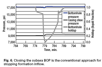
A relevant issue is the risk of exceeding the FP at the casing shoe, i.e. exceeding kick tolerance. An advantage of dual density operations is maintaining a larger kick margin. The example presented provides an 800-psi kick margin at the casing shoe for dual density operations, compared to 200 psi for conventional drilling. The casing shoe pressure increases by 335 psi, which is below the 800-psi kick margin. Consequently, the kick volume of 18.5 bbl should be safely controlled.
The same kick was simulated for conventional drilling operations using single fluid density. The rig pumps were stopped at 4 min. and the BOP closed at 5 min., as before. Total kick volume taken was 16.2 bbl. The pressure increased by 259 psi at the casing shoe, exceeding the 200 psi kick margin. The dual density system�s disadvantages of slightly more difficult kick detection and slightly larger kick volumes are offset by maintaining larger kick margins.
KICK CIRCULATION
Three alternative approaches for circulating out a gas kick after successfully shutting in the well were investigated. These included:
� Circulation up a gas-lifted choke line to a surface choke
� Circulation through a seafloor choke to a gas-lifted choke line
� Circulation through a seafloor choke into the gas-lifted riser.
In each case, the investigation used a simulation that is a follow-up to stopping the formation influx at a kick volume of 18.5 bbl by shutting in the well. When formation flow stops and BHP equals FP, circulation can begin. A special complication is that interpreting the drillpipe pressure buildup to determine the Shut-In Drill Pipe Pressure (SIDPP) is not possible due to the DSV. Therefore, a different method was adopted to obtain an equivalent SIDPP following pump start-up.
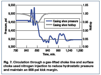
Circulation through a gas-lifted choke line and a surface choke. The first circulation alternative considered is similar to the procedure routinely used on floating rigs. The only difference is that nitrogen is injected into the bottom of choke line at a rate of 7.76 MMcfd to reduce the hydrostatic pressure in the choke line and avoid lost returns. Pump speed was kept constant, and only choke adjustments were used to keep drillpipe pressure and BHP constant. The nitrogen injection rate to the choke line was also kept constant to simplify this procedure. The relatively high, 800-psi kick margin allows the gas kick to be circulated out without any fracturing risk. By keeping the BHP above the FP during gas circulation, there was no additional kick influx, and the gas kick was successfully circulated out of the well, Fig. 7.
Circulation through a gas-lifted choke line with the choke at the seafloor. The second alternative used a surface-controlled, subsea choke system to minimize complications caused by multiphase flow in the subsea choke line. The length of the line can result in unacceptably high hydrostatic and/or frictional backpressure on the annulus during kick circulation. Nitrogen injection into the base of the choke line helps overcome these effects, but it also means that surface choke adjustments always affect the multiphase flow conditions in the choke line. The potential advantage of using the subsea choke is to place the choke ahead of the multiphase flow in the choke line, such that choke pressure adjustments act more directly to affect BHP. This should simplify choke manipulation.
The advantage of using the subsea choke instead of the surface choke is the faster and more accurate pressure response. Kick circulation was successful and the risk of lost returns was even smaller than the previous case.
Circulation through a gas-lifted riser with the choke at the seafloor. The third alternative takes returns through the subsea choke and the gas-lifted riser. This combines the advantages of a subsea choke with a means to avoid friction in the choke line that could cause lost returns. However, it would also incur the risks of riser collapse or overpressuring control equipment at the riser�s top, if a large gas kick was circulated through the gas-lifted riser.
KILL WEIGHT MUD CIRCULATION
Once a kick is removed from the well, Kill Weight Mud (KWM) must be circulated to regain hydrostatic control. This must be done while simultaneously keeping the BHP above the FP and within an acceptable safety margin.
Circulation through the gas-lifted choke line and a subsea choke allowed the most precise control of BHP and was analyzed for KWM circulation. The well is ready for KWM circulation once the kick is removed. KWM density was calculated at 16.3 ppg using the method below. Initial Circulating Pressure (ICP) was 520 psi, Final Circulating Pressure (FCP) was 276 psi. The slow circulating rate, or Kill Circulating Pressure (KCP) was 320 psi. The necessary equations follow:
Kill weight mud is determined by:
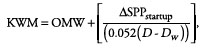
where OMW=original mud weight density in ppg; D=total vertical depth in ft; Dw=water depth in ft.
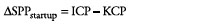
Standpipe pressure is determined by:
Pressure changes related to kill weight mud losses are derived by:
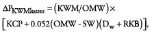
where ∆PKWMlosses = drillpipe frictional pressure losses with KWM to overcome pressure difference at the mudline between a seawater pressure and a drillpipe mud pressure; SW=seawater density in ppg and RKB=air gap between a kelly bushing and a seawater level in ft.
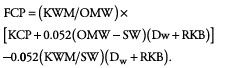
Final circulating pressure can then be determined using:
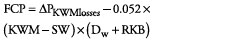
substituting for ∆PKWMlosses yields:
Circulation begins at 1,200 min. when KWM is circulated down the drillstring at the kill rate of 460 gpm and proceeds according to the drillpipe pressure schedule, Fig. 8. Returns are taken through the gas-lifted choke line with the subsea choke. The nitrogen injection rate to the choke line equals 13.45 MMcfd to keep the seafloor pressure equal to seawater hydrostatic pressure. BHP was maintained in the safe pressure range with subsea choke adjustments. The BHP peak at 1,400 min. is caused by KWM entering the choke line. The proper reaction is to open the choke to adjust for additional frictional and hydrostatic pressure increases due to KWM filling the choke line. In conventional well control operations, this rapid pressure increase is offset by proper choke manipulation and near-constant pressure is maintained. However, the transient, multiphase numerical simulator used in this study is not an interactive simulator, and therefore it was not possible to react in time with an immediate choke adjustment to prevent pressure from increasing rapidly.
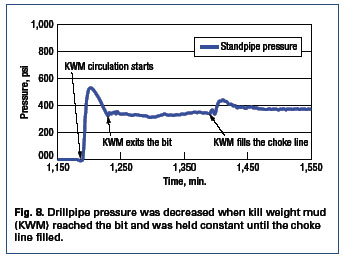
Drillpipe pressure was decreased from ICP of 520 psi to the FCP of 276 psi when KWM reached the bit. Then, drillpipe pressure was kept relatively constant until the KWM began to fill the choke line. The main complication in this case occurs when KWM fills the gas-injected choke line, and pressure at the seafloor is higher than planned.
To keep this pressure constant throughout the kill procedure, the gas injection rate to the choke line was increased to 15.52 MMcfd from 13.45 MMcfd. When KWM reached the casing shoe, casing shoe pressure stabilized at about 9,280 psi.
A simulation of circulating KWM in the single-density, conventional system, was conducted to compare the two systems. Circulation begins at 1,400 min. when KWM is circulated down the drillstring at the kill rate of 50 gpm. This rate was used to minimize choke line pressure losses and the severity of lost returns. The drill pipe pressure schedule, starting with an ICP of 480 psi, was followed until the KWM reached the bit. The SPP was then maintained at a relatively constant FCP value of 284 psi using choke adjustments. When KWM starts to fill the choke line, drill pipe pressure and BHP increase. This is due to the higher frictional pressure losses and higher hydrostatic head of the kill-mud column, in spite of removing the backpressure with the surface choke.
BHP was kept above the formation pressure during KWM circulation. However,
concerns about fracturing at the casing shoe were not avoided and casing shoe pressure exceeded the expected FP at the casing shoe. This is unavoidable for the conditions being simulated where the original kick margin of 200 psi is equal to the increase in hydrostatic pressure
needed to control the kick zone.
CONCLUSIONS
The simulations demonstrate both the advantages of the larger kick margins possible
using a dual density system and the potential for practical well control with a riser gas-lift drilling system. The accuracy of the transient multiphase simulator was suitable for both transient and steady-state conditions compared to a full-scale well unloading test. Riser gas-lift and choke line gas-lift are both technically feasible.
Kick detection for a riser gas-lift, dual density system is essentially conventional,
relying on changes in return flowrate and pit gain. However, a flow check to verify that a kick is in progress is not possible. A kick influx should be shut-in with the subsea BOP, since shutting down riser nitrogen injection without shutting in the BOP is too slow and unreliable for stopping the influx. Use of a DSV is mandatory to minimize the risk of lost returns when the well is shut in.
Kick circulation may be accomplished with returns through the gas-lifted choke line, even for relatively high mud flowrates. Use of a remote-controlled, subsea choke gives faster pressure response with smaller pressure variations and requires fewer and smaller choke adjustments. BHP was kept relatively constant without requiring any variation in the nitrogen injection rate, which should simplify field implementation. Kick circulation with returns through the gas-lifted riser is feasible. Nevertheless, the risk of riser collapse is a concern and is dependent on the kick volume.
Circulation of KWM with returns through the gas-lifted choke line with the subsea choke can be safely implemented. BHP was maintained within safe pressure margins. Problems associated with pressure variations due to new KWM entering the choke line were addressed by an increase in the gas injection flow rate to keep seafloor pressure relatively constant.
Well control with a dual density, gas-lift method is advantageous compared to the conventional single density method, due to more favorable openhole pressure distribution. Therefore, higher kick volumes may be taken with less risk of fracturing and lost returns.
Finally, the data and results presented show that well control procedures for dual density drilling are feasible. Nevertheless, more comprehensive study and full-scale tests will be needed to evaluate this method for field application. 
ACKNOWLEDGEMENTS
The authors thank Scott Penwarden and Dragan Garabiljevic of ENSCO Offshore Co. for time and support, as well as The Research Partnership to Secure Energy for America for funding the research and Scandpower
Petroleum Technology AS for license to use OLGA 2000. The authors also thank LSU Craft and Hawkins Department of Petroleum Engineering: Prof. John Rogers Smith, Prof. Andrew K. Wojtanowicz, Prof. Julius Langlinais, John Shelton and Anamika Gupta. This article was prepared from IADC/SPE 98957 presented
at the IADC/SPE Drilling Conference held in Miami, Florida, U.S.A., Feb. 21�23, 2006.
LITERATURE CITED
1. Durham, Louise S., �Technology focuses on top-hole implementation,� Drilling, December 2002, p. 24.
2. Eggemeyer, J. C., M. E.Akins, P. E. Brainard, R. A. Judge, C. P. Peterman, L. J. Scavone, K. S. Thethi.,
�Subsea mudlift drilling: design and implementation of a dual gradient drilling system,� SPE 71359
presented at the 2001 SPE Annual Technical Conference and Exhibition, New Orleans, LA, Sept. 30�Oct.
3, 2001.
3. Gaddy, E. Dean, �Industry Group Studies Dual Gradient drilling,� Oil & Gas Journal, Aug. 16, 1999, p. 32. 4. Gault, A., �Riserless drilling: circumventing the size/cost cycle in deep water,� Offshore, May 1996, p. 49.
5. Schumacher, J. P., J. D. Dowell, L. R. Ribbeck, J. C. Eggemeyer, �Subsea mudlift drilling (SMD):planning
and preparation for the first subsea field test of a full scale dual gradient drilling system at Green Canyon
136, Gulf of Mexico,� SPE 71358 presented at the 2001 SPE Annual Technical Conference and
Exhibition, New Orleans, Louisiana, Sept. 30�Oct. 3, 2001.
6. Fontana, P., G. Sjoberg, �Reeled pipe technology (DeepVision) for deepwater drilling utilizing a dual
gradient mud system,� IADC/SPE 59160 presented at the 2000 IADC/SPE Drilling Conference, New
Orleans, Feb. 23�25, 2000.
7. Herrmann, R. P., J. M. Shaughnessy, �Two methods for achieving a dual gradient in deepwater,�
SPE/IADC 67745 presented at the SPE/IADC Drilling Conference, Amsterdam, The Netherlands, Feb. 27�
March 1, 2001.
8. Lopes, C. A., A. T. Bourgoyne, �The dual density riser solution,� SPE/IADC 37628 presented at the 1997
SPE/IADC Drilling Conference, Amsterdam, The Netherlands, March 4�6, 1997.
9. Lopes, Clovis, �Feasibility study on the reduction of hydrostatic pressure in a deep water riser using a gas-
lift method,� Ph.D. Dissertation, LSU, April 1997.
10. Maurer Technology, �JIP to develop hollow-sphere dual gradient drilling system,�
http://www.maurertechnology.com/JIP/DGD/DGDProposal.pdf, September 2001.
11. Choe, J., H. C. Jukvam-Wold, �Well control aspects of riserless drilling,� SPE 49058 presented at the 1998
SPE Annual Technical Conference and Exhibition, New Orleans, Sept. 27�30, 1998.
12. Schubert, J. J., H. C. Juvkam-Wold, J. Choe., �Well control procedures for dual-gradient drilling as
compared to conventional riser drilling,� SPE/IADC 79880 presented at the SPE/IADC Drilling Conference,
Amsterdam, The Netherlands, Feb. 19�21, 2003-a.
13. Schubert, J. J., H. C. Juvkam-Wold, C. E. Weddle III, C.H. Alexander, �HAZOP of well control procedures
provides assurance of the safety of the subsea mudlift drilling system,� IADC/SPE 74482 presented at the
2002 IADC/SPE Drilling Conference, Dallas, Feb. 26�28, 2002-b.
14. Smith, J. R., �Comparison of well control concepts for dual density deepwater drilling,� LSU, May 26,
2002
15. Maus, L. D., �Method for installing a well casing into a subsea well being drilled with a dual density
drilling system,� United States Patent 6,328,107, Dec. 11, 2001.
16. Stanislawek, M.: �Analysis of alternative well control methods for dual density deepwater drilling,� Thesis,
LSU, May 2005. Table 1 - Input data for well control simulations.
|
THE AUTHORS
|
 |
Mikolaj Stanislawek earned BS and MS degrees in drilling and geo-engineering from the University of Mining and Metallurgy in Krakow, Poland, and an MS in petroleum engineering from Louisiana State University. His interests focus on rig equipment, deepwater drilling, rig management, and well control. Stanislawek is an engineer for ENSCO Offshore Co. on the ENSCO 7500 semisubmersible in the Gulf of Mexico.
|
 |
John Rogers Smith earned a BS degree in electrical engineering from the University of Texas�Austin and MS and Ph.D. degrees in petroleum engineering from LSU. His teaching and research interests are well control, deep drilling, deepwater drilling, and bit performance. Smith is Campanile professor and an associate professor of petroleum engineering at Louisiana State University. He previously worked over 20 years for Amoco Production Co. in drilling, production, facilities, and research. |
|
|

