COILED TUBING TECHNOLOGY
Abrasive treatment of wellbore casing offers service alternative
High-pressure jet cuts well-casing slots and windows for stimulation or recompletion.
Matt Slezak, Rocky Mountain Oilfield Testing Center
The Rocky Mountain Oilfield Testing Center (RMOTC) and Blast Energy Services Inc. (Blast) recently partnered to conduct testing of Blast’s proprietary abrasive cutting tool technology. The purpose of the project was to determine optimal cutting parameters and to cut well-casing windows of various sizes and shapes, ultimately to test-drill a horizontal microbore beyond the well casing.
Optimal cutting parameters were determined by adjusting the amount of abrasive in the slurry and the speed of the cutting nozzle. The cutting tool presents a number of advantages including lower production costs and increased reserves access. The information obtained from the project could provide the oil industry with an alternative means of well stimulation and recompletion. Having an accurate, cost-effective means of well stimulation and recompletion could reduce costs and increase revenue by optimizing production and recovering additional reserves.
The project was funded in part by a Department of Energy Cooperative Research and Development Agreement and by Blast. It was performed at the RMOTC field site within Naval Petroleum Reserve No. 3 (NPR-3), located about 35 mi north of Casper, Wyoming. Data was collected from field work beginning in October 2006.
The information gathered through the test suggests that the tool is capable of cutting well casings quickly and efficiently. The downhole video camera, available at RMOTC, proved especially useful in this project. The camera’s primary use was to verify operational results in the downhole environment and to diagnose problems. Camera runs verified the cutting patterns and windows cut in the casing. In addition, the camera inferred the horizontal drilling capabilities of the abrasive cutting nozzle.
The study required a sacrificial, low-producing well as a test well. RMOTC was asked to select a shallow well (less than 1,000 ft deep) with 5 ½-in. casing. This depth limit allowed for quick trip times. The test well (42-11-SX) was chosen, based on its limited production and its 51⁄2-in. production casing. The well has 2 3/8-in. tubing and a cast iron bridge plug set at 811 ft. There are two sets of perforations, the first from 628 to 678 ft and the second from 711 to 742 ft.
Due to the size of the Coiled Tubing Unit (CTU), Fig. 1, a large, relatively flat well pad was required. All well equipment near the wellhead was removed to gain access. In this case, the pump jack was moved two to three additional feet away from the wellhead. The next step was to pull the well’s tubing to attach a proprietary Bottom Hole Assembly (BHA) to the end of the 23/8-in. tubing. The BHA was equipped with a junk basket on its bottom to catch metal, cement and formation cuttings.
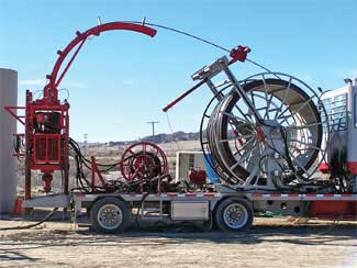 |
Fig. 1. The coiled tubing unit with formation access tool is specially-built for high-pressure cutting.
|
|
The tubing was then re-run with the BHA attached to the bottom of the tubing. New tubing was run to minimize possible scale build up and returns blockage. Wellhead BOPs were flanged onto the wellhead with the Formation Access Tool (FAT) flanged on top of the wellhead BOPs. At this point, a “landing joint” was screwed into the tubing, allowing the tubing and BHA to be directed by the FAT. The coiled tubing BOPs were rigged-up, and finally, the CTU was rigged-up. Abrasive was mixed with field-supplied water to form slurry. The slurry was then pumped through the specially-built, high-pressure CTU. The slurry exited a proprietary nozzle design, cut through the casing and cement, and opened access to the rock formation.
The FAT is controlled by a computer in the cab and allows for vertical and horizontal movement of the cutting nozzle. The computer can be programmed to cut circumferential, vertical and lateral cuts, as well as windows. This allows for virtually any size or shape slot to be cut in the casing. The unique design of the BHA enables the user to quickly change casing sizes. The FAT is capable of up to four feet of vertical travel without repositioning the tubing.
Once the cutting tool was lowered to depth via coiled tubing, the computer was programmed for the cutting action. The window or slot was cut and the tool was pulled out of the hole.
The BHA was set at 692 ft. The initial test phase was to determine optimal abrasive concentrations and cutting speeds. A 180° circumferential cut was made, the tool was then raised 2 in., and the remaining 180° circumferential cut was performed. Cutting took about nine minutes.
The cutting tool was then raised another 2 in., and 12-in. vertical slots were cut into the casing in a saw-tooth pattern at the various abrasive concentrations and cutting speeds. In two hours, 13, 12-in. vertical slots, Fig. 2, were cut through the casing. The tubing was pulled out of the hole, and the camera verified the circumferential cuts, the vertical slots and the first window.
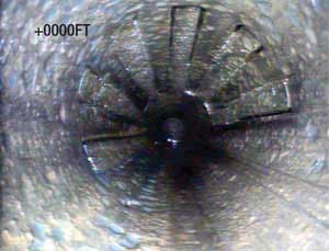 |
Fig. 2. Vertical slots were cut at various abrasive concentrations and cutting speeds.
|
|
The tubing and BHA were then re-run to a depth of 688 ft. This time, a 4-in. by 7-in. window was cut, Fig. 3. The tubing was pulled, and a piece of casing was recovered from the BHA. A camera run verified that a very clean, 4-in. by 7-in. window was cut in the casing and that there was access beyond the cement. Another cut was made and verified by camera. The camera indicated that the tool was very accurate in depth and that the cuts were synchronized with the computer.
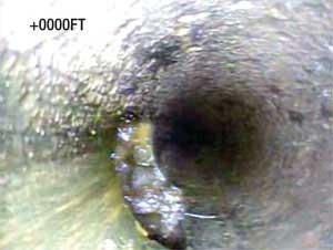 |
Fig. 3. The high-pressure, abrasive slurry cut a 4-in. x 7-in. window in the casing, opening access beyond the cement.
|
|
Additional improvements are required to adapt the unit to cold weather. Because the tool uses water, there were problems with cold temperatures. Blast achieved about 80% of the planned testing before the Wyoming winter weather season caused them to suspend operations until spring.
The test provided significant information about the tool’s abrasive jet cutting capabilities. While some problems were encountered, the company is doing additional testing before it returns to NPR-3 to conduct more tests this spring. The ultimate objective is to increase production in one or more of NPR-3’s production wells using this technology. The company will try a recompletion or stimulation of an existing, producing well in order to increase production from that well. 
ACKNOWLEDGEMENTS
The author thanks Blast Energy Services for the opportunity to publish this article. Special thanks to Steve Nowell, Blast Energy Services and the inventor, Mark McAfee, Alberta Energy Partners, for their contributions.
RMOTC is a Department of Energy field test site for emerging and developing technologies to address critical energy industry issues. NPR-3 is situated in the Powder River basin on the Teapot Dome anticline, the southern extension of the much larger Salt Creek anticline. Over 1,300 wells have been drilled into the structure, a doubly plunging anticline cored by a basement high-angle reverse fault. At NPR-3, there are 600 active wells producing oil and gas from several different geologic formations at depths of 500 ft to 5,000 ft.
Blast Energy Services, Inc. is a Texas-based company performing abrasive jet drilling/cutting as an alternative to existing well stimulation or horizontal drilling services. Its mission is to substantially improve the economics of existing oil and gas operations through the application of worldwide licensed and proprietary technologies.
|
THE AUTHOR
|
|
Matthew Slezak earned a BS degree in petroleum engineering from the University of Tulsa. He has over 20 years' experience, including positions with the Department of Energy's Strategic Petroleum Reserve, an independent exploration company, an LPG storage facility, and an engineering consulting company. Slezak has planned and drilled wells in New York, Michigan, Texas and Mississippi, as well as planned and worked over wells in New York, Texas, Mississippi and Louisiana.
|
|
|


