PRODUCTION
TECHNOLOGY
ESP deployed via riser to lift subsea well
An
innovative solution to slugging and liquid loading in the Gulf
of Mexico increased well production 150%, and may increase overall
recovery 35%.
David Cocciolone and Mike
Parker*, Anadarko Petroleum Corporation; Tiffany Pitts and
Mark Ohl, Baker Hughes Centrilift
The No. 1 well in East Breaks Block 690
is a 4½-mi subsea tieback
to Anadarko’s Nansen spar in the Western Gulf of Mexico. The
well produced 1.7 million bbl oil before pressure depletion caused
slugging and frequent liquid loading in the riser and the subsea flowline
network. Loading of the riser occurred at a 5-10% watercut, leaving
significant reserves in the ground. As such, a viable form of artificial
lift was needed.
In February 2007, an Electrical Submersible
Pump (ESP) was installed in the subsea riser leading to EB 690 No.
1. A Hydraulic WorkOver (HWO) unit was rigged up on the Nansen spar,
and the pump was deployed on 2 7/8-in. tubing through the 6-in. riser.
With the ESP allowing for a lower pressure at the riser base, multiple
benefits have been realized, including the elimination of slugging,
higher fluid rates and the lowering of the reservoir abandonment pressure.
Production increased to 3,500 bopd after installation from 1,400 bopd
(when not loaded up). Based on reserves produced to date, it is estimated
that the ESP will increase ultimate recovery by 35%.
BACKGROUND
East Breaks 690 No. 1, at a water depth
of 4,200 ft, is a subsea tieback located 4½ mi south of the
Anadarko-operated Nansen spar, in which Devon Energy holds 50% interest,
Table 1. Positioned about 118 mi south of Galveston in 3,640 ft of
water, the Nansen spar produces from nine dry-tree wells and six
subsea wells. While all of the dry-tree wells are capable of gas
lift, none of the subsea wells has any form of artificial lift installed.
Some of the subsea wells have been producing for over 5 yr, and pressure
depletion and increasing water production have contributed to decreased
oil production. Therefore, engineering solutions have been sought
to prolong the life of these subsea tiebacks.
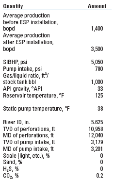
| TABLE
1. Basic well and pump information for East Breaks
690 No. 1 |
 |
|
EB 690 No. 1 is part of a three-well subsea
infrastructure, connected via a piggable flowloop to the two other
subsea wells, Fig. 1. The flowloop has a 5 5/8-in. ID, the same as
the flexible riser tied back to the spar. Both wells on the other
side of the flowloop are shut in due to pressure depletion or high
watercut, but EB 690 No. 1 was still producing 1,100-1,800
bopd. Hydrates have been a major concern throughout the life of the
subject well, and at one point a hydrate formed in the flowline and
had to be dissociated by depressurizing the flowline with nitrogen.
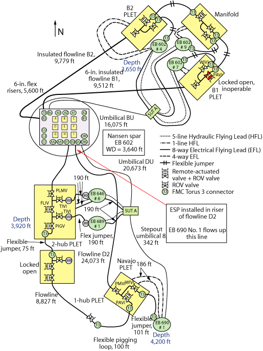 |
Fig.
1. Nansen subsea layout. |
|
Slugging was another issue in the well, caused by a combination of
liquid loading in the 6-in. (55/8-in. ID) riser, low reservoir pressure
and low flowrates. Furthermore, the well became increasingly difficult
to bring online after a shut-in, and at times it would load up during
normal operations. The need for constant monitoring, along with the
lack of sustainable production, led to a review of artificial lift
options.
DEVELOPMENT OPTIONS
One option considered to address slugging
was to place a 2-in. velocity string in the 6-in. riser. This would
mitigate slugging, but would be ineffective in unloading the well,
which was a concern as pressure depletion continued. Gas lift was
proposed to help unload the well, but no means of gas lift were in
place in the wellbore, flowline or riser. One option available was
to send gas down a ¾-in. line
in the existing umbilical to the EB 690 No. 1 subsea Pipe Line End
Termination (PLET) just downstream of the tree. It was determined that
a maximum of 1 MMcfd could be sent down the line; unfortunately, such
a small volume would be insufficient to unload the well and would not
provide a long-term artificial lift benefit.
However, lowering the riser hydrostatic pressure as much as possible
was still a priority, and an ESP was considered a viable option. By
boosting pressure at its installation point, an ESP could lower the
intake pressure at that point and prevent slugging. Also, the hydrate
risk would be reduced by having steady flow in the pipeline network.
Furthermore, the abandonment pressure would also drop, allowing additional
recoverable reserves to be produced.
When considering ESP (or any other artificial
lift) proposals, two options were available: to run the ESP from
the spar and install it in the riser to boost fluid from near the
seafloor, or to run the ESP in the subsea well and hook up power
to it from the spar. Installation costs to run the ESP in the riser
included the spread rate of an HWO-about
US$25,000 a day. To run the ESP in the subsea well would require a
floating intervention vessel, running up to $500,000 a day. Furthermore,
supplying power to the ESP in the subsea well would cost millions of
additional dollars. All in all, subsea intervention would have likely
cost about $30-40 million vs. about $2.5 million to run the ESP
in the riser.
Given the reserve estimates of the existing completion, installing
an ESP at the base of the riser was found to be the best economical
option to mitigate slugging, prevent load-up, produce at higher rates
and increase ultimate recovery. The only question remaining was whether
the project was feasible to pursue on the Nansen spar.
PROJECT DESIGN
The first step was to ensure adequate access to the riser. Fortunately,
the risers on Nansen were designed to be accessible via coiled tubing
if for some reason a washout of the flowline was required. The necessary
power supply was available on the spar, which has two generators capable
of producing 5,000 kW. At the time, only 2,000 kW were in use, leaving
plenty of power to run a pump. Space on the platform was then found
to accommodate the drive and transformers. Running an ESP down the
riser was judged to be feasible, so design work proceeded.
Pump design. The well
had a low drawdown, a high productivity index, was gravel packed
and was capable of producing greater volumes if a larger drawdown
could be achieved. Modeling of the wellbore, flowline and riser showed
that a pump with the maximum fluid throughput would be required.
Baker Hughes’ Centrilift
400-series P60SXD pump, with a high-volume pump stage and capability
of landing in a 5 5/8-in. ID riser, was selected.
Downhole and surface issues. One potential
problem for the pump was the well’s high gas fraction at the riser base. Every stock tank
bbl of oil was accompanied by 1,000 ft3 gas, and gas fraction at the
pump intake was 46%, close to the pump’s handling capacity at
the design intake pressures.
Fortunately, the existing setup allowed
for options to reduce the gas fraction at the intake. With the ESP
run on tubing inside the existing production path (i.e., the 6-in.
riser), gas could be separated before it entered the pump both by
natural separation and by the inclusion of a vortex gas separator
in the pump string. The gas could then be sent up the riser/tubing
annulus to production. The liquids would be sent through the pump,
up the tubing and into the existing production manifold. In order
to direct gas on the backside to various production vessels, a new
manifold on the Nansen spar would have to be constructed. Pump production
(through tubing), annular production or both could be sent through
a test separator, which would make it possible to a) determine how
much gas is entering the pump and b) monitor the seperator’s
efficiency.
With downhole separation sending gas to the annulus, special consideration
would need to be taken regarding materials. Though the gas only had
a CO2 molar fraction of 0.2%, the possibility of 4 MMcfgd traveling
up the backside meant that any equipment run in the riser would need
to be CO2-corrosion resistant. Furthermore, the riser was constructed
of 304L stainless steel, and material compatibility was a concern.
Because of these issues, all string components where designated as
stainless steel or equivalent. The tubing would be composed of 13-chrome,
the cable protectors of stainless steel and the ESP housing also of
chrome. Because the integrity of the cable was of particular concern,
it was decided to use a Monel armor to protect the cable and ensure
material compatibility. A lead barrier was also included in the cable
design to reduce the risk of gas intrusion causing a premature electrical
failure in the cable.
Downhole monitoring was also considered an important criterion because
the well was capable of high production rates and because the flowline
had experienced large pressure drops due to hydrates. A Centrilift
Centinel downhole gauge was included to monitor downhole pressure,
temperature and motor temperature. The ability to monitor the pressure
drop between the subsea wellhead and the pump intake (near the base
of the riser) would help in monitoring pipeline performance over the
life of the well. Action, such as increasing the methanol injection
rate, could then be taken immediately if any abnormal pipeline pressure
drop was detected.
Other technical challenges to installation remained. The riser in
which the ESP was to run had no means of hanging tubing, and therefore
a wellhead would need to be fabricated and landed above the riser.
The wellhead would serve two purposes: as a location to land the tubing
hanger and to send the annular production to a new manifold. The wellhead
had to be custom made to land on the adapter flange below and tie into
the shutdown valves above.
ESP string test. The flexible riser in
which the ESP was placed moves somewhat in rough weather. However,
with the ESP and tubing landed on a wellhead attached to the spar,
movement would be in the same line, reducing vibration between the
ESP assembly and the riser. Nonetheless, the operator wanted to ensure
that the pump would see as little vibration as possible. A string
test would ensure proper fit of all downhole components and verify
the system’s
operation in a downhole environment. The test parameters monitored
were head, flow, skin temperature of each system component and vibration
signature of the system.
All components of the downhole ESP assembly, from the downhole guage
to the pump, were run in a test well. During initial testing, vibrations
of frequencies above recommended levels were observed in several components.
Since these frequencies were likely to occur offshore, the components
were disassembled and the critical components were inspected. No visible
or dimensional problems in the shaft, bearings or other components
were found. The ESP was then assembled and re-tested. The resolution
of the vibration instrumentation was increased to further separate
frequency peaks. With the finer resolution, the peaks were identified
as half-speed oil whirl in the journal bearings. An additional test
was run with a higher-viscosity motor oil. This brought the vibration
readings within acceptable limits and still allowed for proper lubrication
properties at design conditions.
Modeling the well network in existing conditions was nearly impossible
due to dips in the flowline and slugging. It was quickly realized that
the well would need many adjustments to optimize flow upon startup.
Due to the 5-mi length of the flowline, the history of gas slugging
and declining bottomhole pressure, a Variable Speed Drive (VSD) would
be necessary for control. A VSD was requested, and although the spar
has limited deck space, adequate room was found to securely place the
drive, transformers, annulus manifold and wellhead.
ESP INSTALLATION
Each of the three subsea wells tied into the flowline and riser has
three isolation valves at the tree, as well as a surface-controlled
subsurface safety valve. The ability to isolate the riser from well
pressure allowed easy access to the riser and flowline and greatly
simplified installation of the ESP. To ensure that the riser was safe
to access during installation, the flowline would be displaced with
10.4-ppg CaCl2 to dissociate any potential gas pockets that remained
and to clean any paraffin or other buildup.
A method of ESP installation still had
to be chosen. If jointed tubing was run, then either a platform rig
or a Hydraulic WorkOver (HWO) unit would be needed. Running the ESP
via coiled tubing was another option, but 2 7/8-in. chrome coiled
tubing was not available at the time. In the end, an HWO was preferred,
as it is quick and inexpensive to mobilize. Furthermore, no pressure
control, and thus no BOPs, would be needed, saving on cost and rig-up
time. Although an HWO does not run tubing as quickly as a rig, the
short length of pipe to be run minimized this factor.
After the flowline was displaced with fluid, the flowline valves above
the riser tieback were nippled down and the wellhead fabricated for
the job was made up to the existing double-studded adapter, Fig. 2.
This is where the tubing hanger would be landed and cable penetrations
made.
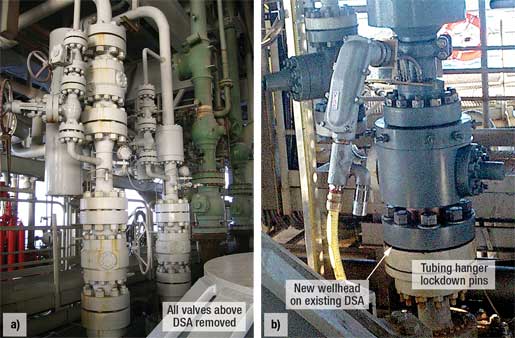 |
Fig.
2. Valves above the riser tieback (a) were
removed, and the new wellhead was flanged up (b) to
the existing double-studded adapter to facilitate the
tubing hanger and cable penetrations. |
|
Because no pressure control was required, the ESP and tubing were
run with no riser above the wellhead, Fig. 3. A bell nipple was manufactured
to allow diversion of fluid to a tank in case any was displaced out
of the flowline riser when running the ESP in the hole. The ESP assembly
was guided into the bell nipple above the wellhead. Simultaneously,
the cable was being spooled onto the pipe and clamped onto the tubing
at the access window. It took slightly less than 24 hr to run 3,124
ft of tubing and the downhole components with cable and clamps. To
facilitate fluid flow up the annulus, no downhole packer was set and
the assembly was not rigidly connected to the riser downhole. All the
weight of the tubing and pump components was distributed at the wellhead.
The tubing hanger was run through the HWO as well, and all penetrations
through the hanger were made at the access window, Fig. 4. The hanger
was then landed and the tubing bonnet installed with the penetrator
wires running through, completing the HWO.
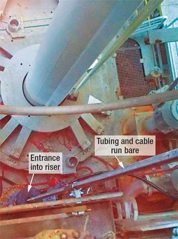 |
Fig.
3. Tubing and cable were run riserless through
the wellbay into the EB 690 No. 1 riser. |
|
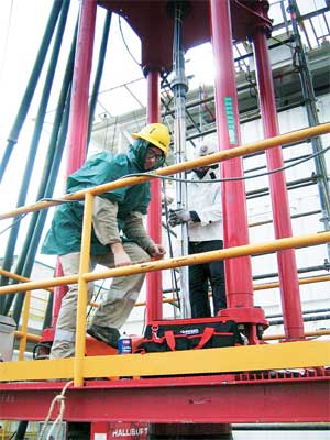 |
Fig.
4. All penetrations through the tubing hanger
were made at the access window. |
|
After the ESP was RIH, the VSD was picked up and placed in the motor
control center. Laying of cable trays and pulling of cable having been
previously completed, wiring was now terminated into the junction box,
transformers and VSD. Together with the Human-Machine Interface (HMI)
programming, this took a few days.
Drive control. The operator desired full
control of the ESP from the HMI interface. This required having a
programmer on board to program the control functions into Wonderware,
Anadarko’s
proprietary HMI system. From a computer terminal, the operator can
start or stop the pump and adjust its frequency with a mouse click.
The downhole gauge relays the intake pressure, intake temperature,
motor temperature and other subsea data to the same computer terminal.
This data can be trended with the touch of a button to better monitor
and troubleshoot.
Unloading CaCl2. About 900 bbl of 10.4-ppg CaCl2 in the flowline and
riser would need to be displaced before wellbore fluid would reach
surface. The heavy fluid initially gave the pump some difficulty, causing
it to take a long time to speed up to the minimum required frequency.
Once the pump reached that speed, flow was rather erratic, with rates
fluctuating wildly. However, once all the heavy fluid was out of the
system, rates and pressures began to behave as expected.
WELL STARTUP
After the CaCl2 was displaced out of the
line, the pump started to run more easily. When the pump was run
at target frequency, the downhole electrical current was observed
to fluctuate significantly-anywhere
from full load (35 A) to underload conditions. These underload conditions
resulted from slugs of gas moving through the pump, causing it to run
nearly in idle. To alleviate this, the pump was programed to speed
up whenever gas entered the pump (i.e., under low-current conditions).
The increased frequency would allow the pump to do more work, avoiding
extreme underload conditions.
A high-current limit was also programed
in. When fluid would hit the pump, increasing the load to nearly
35 A, frequency would automatically adjust lower to prevent the load
from exceeding 35 A. The frequency never adjusted below 54 Hz-still
sufficient speed to move fluid through the pump. The pump control
continues to be set at a target current, with frequency being adjusted
automatically to maintain a proper load.
After this adjustment was made, EB 690 No. 1 was tested by sending
both the tubing and the annulus production to the test separator. A
12-hr well test resulted in production of 3,931 bopd, 3.9 MMcfgd and
85 bwpd. Liquid dumping from the separator was fairly constant, and
slugging was not a serious problem. One unknown that remained was the
ratio of production through the tubing (pump) to production through
the annulus. To find this value, the tubing production was sent to
the test separator and the annulus production was sent to the Intermediate
Pressure (IP) separator, with both vessels at nearly the same pressure.
This would reveal not only rates from both sides, but also how much
gas was being diverted to the annulus, i.e., the effectiveness of the
gas separator. Results of the test were as follows (adjusted for conditions
at pump intake):
- Oil production through pump:
2,254 bpd
- Gas production through pump:
1.6 MMcfd
- Oil production through annulus:
1,879 bpd
- Gas production through annulus:
1.8 MMcfd
As shown, about 55% of oil is produced through the pump, along with
about 45% of gas production. Surprisingly, a sizable amount of the
fluids are producing up the backside. Though the gas separator is not
separating gas as efficiently as expected, this does not appear to
affect total volumes.
Pressure response. ESP intake pressure
at the base of the riser holds fairly steady at just under 800 psi,
whereas unboosted pressure at this depth was 1,500 psi. This corresponds
to a lower flowing tubing pressure with the ESP than without, Fig.
5. The pressure drop is transferred all the way to the perforations,
and has greatly increased reservoir drawdown-to the point where
the well is slightly choked back in order not to exceed reservoir
voidage guidelines. Flowrates before and after ESP installation can
be seen in Fig. 6.
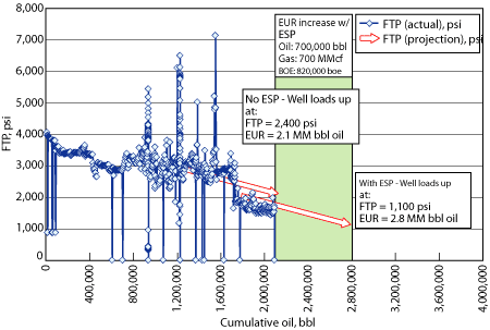 |
Fig.
5. Flowing Tubing Pressure (FTP) for EB 690
No. 1 is plotted against cumulative oil production.
Linear trends before and after ESP installation are
extended to load-up pressure. |
|
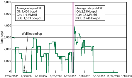 |
Fig.
6. Flowrate for EB 690 No. 1 before and after
ESP installation. |
|
WELL EXPECTATIONS
It is expected that the EB 690 No. 1 will
continue to produce at higher rates due to the reduction of the bottomhole
pressure, resulting in higher drawdown and the mitigation of severe
slugging. It is anticipated that boosting the riser will reduce the
abandonment pressure of the well by 500 psi. Based on historical
well production, a 500-psi abandonment-pressure drop will increase
the well’s estimated ultimate recovery by
about 35%.
FUTURE APPLICATIONS
Anadarko is already looking at future applications for ESP riser lift.
Potential uses for this technology are in subsea tiebacks with no form
of artificial lift previously set up in the following environments:
- Oil wells with gas fraction
at pump low enough for an ESP to handle (downhole separation may
be required)
- Confidence that the watercut
will not rapidly increase with depletion, possibly resulting in unfavorable
economics
- Sufficient power at the facility
to run the pump, as well as adequate room for transformers and the
drive
- A means of accessing the riser
in order to run the ESP
- The riser in sufficient water
depth to provide meaningful pressure boosting.
At the time of this writing, Anadarko has six spars and one TLP in
the deepwater Gulf of Mexico, all with subsea tiebacks. As the wells
become more mature and artificial lift becomes necessary to prolong
field life, riser lift via ESP will be a viable option for many of
these facilities.
CONCLUSIONS
Running an ESP in the riser tied into
the flowline of the EB 690 No. 1 well resulted in immediate benefits.
Production increased by 2,500 bopd (2,900 boepd), slugging was mitigated,
and liquid loading ceased to occur. Long-term benefits will be realized
as well, as EUR is expected to increase by 35% with the lowering
of the abandonment pressure. Overall economics look very sound, with
finding and development cost for this project under $4/boe. With
the success of the ESP installation and results realized, other candidates
will be evaluated as subsea wells continue to mature. 
|
THE AUTHORS |
|
David
Cocciolone is a senior completions engineer for
Anadarko and has spent the last three years working as a
production engineer in the deepwater Gulf of Mexico. He started
his career in 2001 with Kerr-McGee Oil and Gas, holding positions
in drilling, reservoir and completions, mostly offshore.
Mr. Cocciolone earned a BS and an MS degree in petroleum
engineering at Texas A&M University, along with a master’s
degree in petroleum economics and management from Institut
Français du Pétrole. |
|
| |
Mike
Parker is Operations-Engineering manager for Crimson Exploration.
Before joining Crimson, he was the Gulf of Mexico production
engineering manager for Anadarko. In this position, Mr. Parker
is responsible for overseeing production engineering for the
company’s nine operated deepwater GOM facilities. He earned
a BS degree in chemical engineering at Purdue University in 1981,
after which he joined Amoco Production Company. Mr. Parker has
spent most of his career working on artificial lift and production
optimization issues in the US and, for seven years, in Jakarta,
Indonesia, for Maxus Energy. While in Jakarta, Mr. Parker was
responsible for managing Maxus’ 450 offshore operated ESP
wells. |
|
| |
Tiffany
Pitts is a strategic account manager for Baker Hughes Centrilift.
Ms. Pitts joined Centrilift in 2005 and has worked as an applications
engineer, project coordinator and tender team manager. She earned
a BS degree in chemical engineering at Auburn University and
an MS degree in neuroscience at the University of Houston. |
|
| |
Mark
Ohl is a senior operations account manager for Baker
Hughes Centrilift. Mr. Ohl has 26 years’ experience in
the petroleum industry, 23 of which have been in the ESP sector.
He joined Centrilift in 1992 and has worked in the major producing
areas of the lower 48 states as well as the GOM. For the last
five years, he has focused on projects in the Continental Shelf
and the deepwater GOM. Mr. Ohl earned a BS in business administration
from Emporia State University in Emporia, Kansas, USA. |
|


