Production Technology
Preserving well integrity with pre-job testing
Oxygen-free acid stimulation restores blocked pre-packed screens in an underground gas storage well.
S. Yntema, P. de Boer and R. A. Trompert, NAM, R. M. de Jonge, BJ Services Co., and B. J. van Gellekom, Baker Oil Tools
The Netherlands is home to underground gas storage wells that are used to inject and store natural gas during summer months. Throughout the winter, the wells produce gas during peak delivery periods. To ensure that Nederlandse Aardlie Maatschappij’s (NAM) Grijpskerk Underground Gas Storage met its contractual obligation to deliver adequate gas during the peak period (total peak capacity 2,000 MMcfd) Well GRK-47 needed its production and injection rate restored. NAM performed a coiled tubing (CT) acid stimulation to restored the well’s capacity.
The well’s performance declined by 52.5 MMcfd over the years, leading the operator to suspect scale, fines and/or drilling damage. Since the well was completed with pre-packed screens in a sandstone reservoir, the impairment increased the drawdown over the screen to 1,450 psi, jeopardizing screen integrity, as well. The screen has a differential pressure rating of 1,000 psi.
An acid screen wash and mud acid squeeze was proposed to remove the impairment and reduce drawdown. However, it needed to minimize negative impacts to the well and surface facilities. To ensure this, job preparation investigated potential damage mechanisms.
Well GRK-47 is partially completed with 7-in. and 7-5/8-in. tubing, a 7-in. blank liner and a 7-in. pre-packed screen from 10,735 ft to 11,293 ft, Fig. 1. This wire-wrapped screen consists of pre-cured, resin-coated, gravel pack (20-40 mesh) and mesh wire supported by a perforated inner tube, Table 1. The gas has 1.38% CO2 by volume and no H2S.
 |
Fig. 1. Well GRK-47 is completed with 7-in. and 75/8-inch tubing, a 7-in. blank liner and a 7-in. pre-packed screen from 10,735 ft to 11,293 ft.
|
|
| TABLE 1. Technical specifications of the pre-packed screen. |
 |
|
PREPARATION AND TESTING
While considering the acid treatment, concerns were raised about the effect of the pre-flush HCl acid and main stage mud acid on the strength and solubility of the resin-coated gravel pre-pack1 and the corrosion of the screen parts. Three properties were tested:
- Bonded gravel Unconfined Compressive Strength (UCS) after acid exposure
- Screen component corrosion with inhibited acid
- Jetting pressure effects on the wire mesh screen.
Gravel pre-pack testing. In the laboratory, technicians tested the UCS of resin-coated-gravel core plugs for various mesh sizes, before and after soaking in HCl and mud acid.2
Ceramic core plugs (20 – 40 mesh) were prepared by weighing out 125-gram batches of resin-coated gravel. Each batch was poured into a 1-1/2-in. ID curing cell. The cells were placed in an oven heated to 300°F and allowed to cure for four hours. After removing and cooling, the plug ends were trimmed leaving 2.6 – 2.7-in. plug lengths. Technicians prepared six core plugs.
Core plug 1 established a compressive strength baseline. The plug was placed vertically in a cement hydraulic press (Versatester). The press piston was flat and fitted flush onto the core face. A continuously increasing hydraulic force was applied against the core face until the core failed. Core plugs that were exposed to acid were rinsed thoroughly with fresh water prior to crushing.
Untreated plugs have compressive strengths dependent on mesh size, ranging from 1,952 psi for 30 – 60 mesh to 1,500 – 1,324 psi for 20 – 40 mesh and 1,132 psi for 12 – 20 mesh, Table 2.
| TABLE 2. Unconfi ned compressive strength of the ceramic pre-pack material exposed to acid for two hours and 16 hours at 117°C, representative sample. |
 |
|
The UCS significantly decreases after acid exposure, even after two hours. Also, UCS is affected as much by HCl as by mud acid. The 12% HCl/3% HF mud acid was the most damaging. However, soaked plugs were still properly consolidated, Figs. 2a and 2b. The solubility of the gravel pre-pack in 15% HCl was 2.3% weight loss; while in the 13.5% HCl/1.5% HF mixture, it was 6.4%.
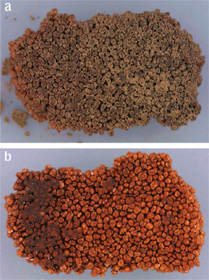 |
Fig. 2. The unconfined compressive strength of the plugs significantly decreases after acid exposure, however, soaked plugs were still consolidated: (a) after exposure to 15% HCL, (b) after exposure to 13.5% HCl/1.5% HF.
|
|
Screen component corrosion. The acid resistance of the pre-packed screen, mesh wire and pre-packed gravel sand had to be tested to ensure that their integrity would not be jeopardized by the treatment recipe.
Several corrosion tests on samples of the actual screen were carried out in the laboratory with the proposed treatment recipes, Table 3. This established the required corrosion inhibitor loadings for the acid recipes. In addition, technicians investigated the integrity of the mesh wire and pre-packed sand.
| TABLE 3. Corrosion inhibition recipes. |
 |
|
Because of the mesh wire shape, establishing the weight loss per square foot alone would not be an appropriate measure. A microscopic visual examination was performed to evaluate mesh-wire integrity following a 12-hr acid soak at bottomhole temperature. Visual inspection of the mesh wire after the acid soak at 120X magnification showed no damage to the screen. Sand integrity was examined by Gravimetric Solubility tests, with acceptable results.
Corrosion inhibition tests were performed separately on the individual screen components, including the base pipe, mesh and wire-wrapped screen. Additional tests were done on the CT material, Table 4.
| TABLE 4. Corrosion weight loss (at 117°C, 275 bar). |
 |
|
The first test with the perforated 13Cr base pipe using the main flush showed a 20% higher weight loss compared to standard 13Cr coupon material, which was used in the internal screening tests. It had a corrosion weight loss of slightly more than 0.05 lb/ft2, which is the industry accepted weight loss criterion. The base pipe was re-tested after it was bead-blasted to remove the outside oxide coating. While this coating is effective at preventing CO2 corrosion, it is more soluble in HCl and mud acid, which affects the measured weight loss. The bead-blasted coupons then showed weight loss below 0.05 lb/ft2.
The Incolloy825 wire-wrapped screen is well protected on the outside and shows very little weight loss. The slots in the screen were examined before and after the acid exposure test and no difference was detected.
NAM regarded wire-mesh corrosion as most critical property. If the mesh screen fails and the bonding strength becomes insufficient, then the pre-packed gravel can be removed from the screen. If the mesh screen is not affected, the loss of strength in the pre-pack is less relevant, since it will be held by the screen. Testing showed that the 316SS mesh screen could be protected against corrosion. The weight loss was very low and scanning electron micrograph pictures of the screen before and after the test showed no difference with only a slight loss of its shiny finish.
Testing of the individual screen components showed that the proposed recipe would not jeopardize the well’s integrity.
Jetting the wire mesh screen. An important concern was the potential damage to the mesh wire from jetting impact during the screen wash. To assess the effect, four different jetting tools were tested using a:
- High impact rotating jetting tool with 2x45° jets
- Low impact rotating/ pulsating jetting tool with 4x45° angled holes
- Jet nozzle with 45° angled holes, no rotation
- Jet nozzle with 90° angled holes, no rotation
The test was done with four, two-foot sections of pre-packed screen. Each section was welded on bars and fixed on a forklift truck, Fig. 3. To test integrity, the sections were jetted with water at the same rate, using different jetting nozzles.
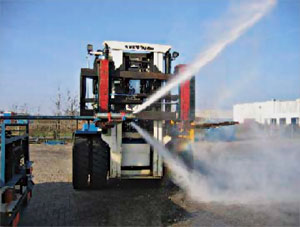 |
Fig. 3. Screen integrity was tested by jetting four, two-foot sections of pre-packed screen using different nozzles.
|
|
Because a 7-in. pre-packed screen was not available, the test was performed using a 4-1/2-in., but similar, pre-packed screen. The smaller diameter of the screen made the test more conservative, since the impact of the jetting force is higher with the stand-off of the jets closer to the screen. These test screens had been retrieved from other underground storage wells (NORG) in 2001 – 2002, cleaned and stored vertically. All test sections originated from one screen joint. Although the actual operation was programmed for four passes, the preliminary tests were performed with eight passes, using water pumped at 1 bpm (150 l/min).
The nozzle was centralized, so that the screen could move across the nozzle using a forklift truck. The bottom half of the screen was shielded by a half-piece of pipe, so that the exposed screen could be compared with the protected part. Although not measured, the impact pressure of the jets of the rotating/ pulsating tool on the 4-1/2-in. screen was simulated with a software program and was found to be about 230 psi (15-16 bar) at 1 bpm.
No mesh-screen damage was seen after the test. Screen samples were cut and the mesh was removed from the screen. Closer observation showed that there was no damage to the mesh wire or to the pre-packed sand using the low impact rotating/ pulsating jetting tool and the jet nozzles.
It should be noted that the screen samples were clean and that the test examined structural damage only, not cleaning efficiency. To effectively test jetting efficiencies cavitation effects must be removed by performing the test under pressure. Case histories of screen cleaning with rotating jetting technology have previously been reported.3
After the test the screen was cut and examined. The top-half of the screen was protected during the test. The position of the holes in the base pipe were seen on the mesh screen, but showed that there was no significant difference between the protected part and exposed part of the screen. The bonded pre-pack was still intact.
TREATMENT AND CLEANOUT TOOLS
Laboratory tests established appropriate acid treatments for GRK-47. The yard test with the different jet nozzles showed that the low impact rotating/ pulsating jetting tool and the two jet nozzles were non-damaging and were suitable for use during the screen wash and stimulation treatment. To ensure coverage, the rotating tool was the preferred choice.3 The rotating/ pulsating jetting tool induces hydraulic vibrations from the pulsating jets. These vibrations dislodge insoluble fines in the pre-packed screen and can open pore space normally unaffected by the treatment fluid’s chemical action.
Due to high wellhead pressure, nitrogen had to be pumped simultaneously with the treatment fluids. This increased the pump pressure to stay within the CT’s collapse limits. The effect of nitrogen on the jets’ impact pressure against the screen was not considered in the yard test. To avoid problems, the nitrogen needed to be separated from the treatment fluids downhole, just above the jetting tool. A novel nitrogen-phase separation tool was used for this purpose.
The CT bottom hole assembly included:
- 1-3/4-in. CT connector
- 2-1/8-in. OD double-flapper check valves
- 2-1/8-in. OD ball-operated shear sub
- 2-1/8-in. OD downhole filter
- 3-3/8-in. OD centralizer
- 2-1/8-in. OD nitrogen-phase separation tool
- 3-3/8-in. OD centralizer
- 2-1/8-in. OD rotating/ pulsating jetting tool.
The treatment used four stages and had total pumped volume of about 9,170 gal, Table 5.
| TABLE 5. Pumped treatment and volumes. |
 |
|
REDUCING OXYGEN AND CHLORIDES
To minimize corrosion in the well and at the production facilities, the oxygen and chloride content in the system had to be kept to a minimum. To minimize the oxygen content of the fluids injected, the acid solution was agitated with nitrogen prior to pumping. An oxygen scavenger was also added to the recipe. The chloride content of the return fluids was diluted by injecting oxygen-free water into the flowlines. To create an oxygen-free environment, the water tank for diluting the return fluids was purged with nitrogen prior to filling. Once filled with water, the oxygen scavenger was added.
The water was now stored in an oxygen-free and closed environment. To prevent the tank from collapsing when sucking water from the tank for injection, a positive pressure was applied to the tank. This was done using a nitrogen vaporizer equipped with a pressure regulator. This ensured 30 psi (2 bar) on the water tank at all times.
During the well cleanup stage, dedicated laboratory equipment monitored and analyzed the oxygen and chloride content of the return fluids. If chloride levels exceeded pre-set values, more oxygen-free water was injected to reduce the level. This would lower the oxygen levels of the produced stream. A back-up injection skid was ready to inject caustic soda, if the pH dropped below 2.5.
A SUCCESSFUL OPERATION
The CT intervention and back production of fluids on GRK-47 was completed in six days, working 24 hr/d. The acid mixture was prepared by agitating with nitrogen and the return fluids were diluted with oxygen-free water. By continuously monitoring pH, oxygen and chlorides, the integrity of the surface facilities was ensured. Table 6 shows the guidelines used. During production, specified levels were not exceeded. Note that the oxygen level was kept below a maximum 20 ppb at all times.
| TABLE 6. Chloride, oxygen content and pH guidelines for the produced fluids. |
 |
|
After pumping the first stage (15% HCl for screen ID cleaning), a positive side effect of oxygen-content reduction was noted. Since the mud acid was pre-mixed, it was kept in tanks for 24 hr before the operation resumed. Before pumping the mud acid, the iron content of the mixed acid was checked and found to be less than 100 ppm. This is less than comparable cases, where acid was rejected because of high iron content (after mixing it too early).
Following the intervention, the production rate of GRK-47 increased from 160 MM to 230 MMcfd (4.5 MMm3/d to 6.5 MMm3/d). The increase in production capacity is 18 MMcfd (0.5 MMm3/d) higher than the well’s initial performance, Fig. 4. Long term integrity of the well was ensured by halving the total drawdown, over reservoir and screen, from 1,450 psi to 725 psi, well within the screen’s pressure rating.
 |
Fig. 4. Following the intervention, the production rate of Well GRK-47 increased from 160 MMcfd to 230 MMcfd, 18 MMcfd higher than the well’s initial performance.
|
|
CONCLUSIONS
The acid wash/ acid stimulation intervention with CT was successfully performed in underground gas storage well GRK-47, using a process developed to produce an essentially oxygen-free stimulation treatment. Chloride levels were controlled in the produced fluids after an acid treatment by dilution with oxygen-free water.
Testing showed that the rotating/ pulsating jetting tool did not damage the resin-coated gravel and pre-packed screen used in the treated well. Using the tool in combination with the nitrogen phase separation tool was a perfect choice for performing the acid wash and stimulation treatment in this well, because of its pre-packed screens.
Iron content was minimized by storing acid at the surface in an essentially oxygen-free environment. 
ACKNOWLEDGEMENTS
The authors thank Shell Exploration & Production Europe, BJ Services and Baker Oil Tools for permission to use the data presented in this paper. They also thank the NAM well services crew, production chemistry laboratory technicians, BJ CT operators and production operation staff involved in the project.
This paper was presented at the 2006 SPE/ ICoTA Coiled Tubing and Well Intervention Conference and Exhibition held in The Woodlands, TX, April 4 – 5, 2006.
REFERENCES
1 Evans, B. et al., “Effect of acid on resin coated gravel in pre-packed screens,” SPE 39588, 1998.
2 Baker Oil Tools Report no. 0502037 (ref. A. Gabrysch), dd. February 15, 2005.
3 Stanley, F.O. et al., “Rotating jet technology improves stimulation fluid placement to effectively treat horizontal and gravel packed wells – lab model tests and global results are reviewed,” SPE 90174, 2004.
|
THE AUTHORS
|
|
S. Yntema earned a MSc degree in petroleum engineering from Heriot-Watt University and is a senior production technologist with Shell, based in Damascus, Syria. He is working with Al Furat Petroleum Co., a joint venture of Shell and the Syrian Petroleum Co. He was part of the Groningen field development team for four years and was project lead for the GRK-47 stimulation. Yntema and has been a SPE member for eight years.
|
|
|
Peter de Boer is a production technologist VC with Nederlandse Aardolie Maatschappij B.V. (NAM), the Dutch operating arm of Shell Exploration & Production Europe. He is based in Assen, The Netherlands.
|
|
|
Ruud A. Trompert is team leader-process chemistry with NAM in Assen.
|
|
|
Robert DeJonge earned an MS degree in petroleum engineering from Delft University of Technology in The Netherlands. He is senior district engineer with BJ Services’ Well Services Division, Continental Europe. DeJonge has 11 years’ experience in the oil industry with an in-depth knowledge of coiled tubing and stimulation services. DeJonge has been a member of the SPE for 14 years, and is based in Emmen, The Netherlands.
|
|
| |
Ben J. van Gellekom is district engineer for Baker Oil Tools on the Cased hole/ Open hole Completion department for NAM. He is based in Velsen-Noord, The Netherlands.
|
|
|

