|
Vol. 227 No. 11 |
| |
 |
Shape-sensing mat gives real-time load, fatigue data on deepwater risers
The mat has been developed and successfully deployed in 6,000 ft of water on a Gulf of Mexico completion riser, as well as to monitor an SCR in another development.
Damon Roberts, Insensys, and Dr. Thanos Moros, BP Exploration
The drive to develop deeper fields, coupled with environmental, legislative and financial expediency, has led to an increasing need to monitor loads in real time and track the load histories of deepwater risers and flowlines. The demands of deep, extended subsea operations have challenged conventional strain gauging. Practical difficulties of bonding and protecting strain gauges, plus ongoing calibration issues, have restricted development of structural health monitoring technologies. Alternative techniques based on interpretation of second-order effects that can be more readily measured (e.g. accelerometers and inclinometers) have been preferred.
Fiber optic-based measurement offers substantial advantages over historic strain gauges. Although relatively novel, the technology has matured through the Telecom industry. The fiber optic sensor is extremely sensitive, provides absolute data (no repeated calibrations required), is immune to electromagnetic radiation, is unaffected by pressure and water, and is intrinsically safe. The use of fiber optics as the prime sensing device shows how they can be embedded in composite sensing mats to create robust, easily deployed, subsea sensing.
FIBER OPTIC STRAIN SENSING
A key to the Fiber Optic Strain Sensing system is an optically altered region in a fiber optic cable core that changes the wavelength of light passing through (or reflected by) that part of the cable, as a result of change to longitudinal compression or tension. Such altered areas create the sensor. A typical fiber optic system comprises:
- Sensors (that are part of the fiber optic cable core)
- An electro-optical interrogator
- Presentation hardware and software
Sensor element. The sensor, known as an FBG (Fiber Bragg Grating), is an optical interference pattern created within the core of standard, single-mode fiber optic cable at a discrete point. At this point, the cable's light transmission is altered, so that when the cable at this point sees longitudinal strain (compressive or tensile), the wavelength of the transmitted or reflected light is shifted. The shift in wavelength is directly proportional to the longitudinal extension or strain at that point. This absolute measurement of wavelength, alone, provides for one of the system's principal benefits. Such sensor elements are within the cable's core (there is no physical external presence) and can be created at multiple points along a single fiber optic cable. The fiber optic cable is five-thousandths of an inch (0.125 mm) in diameter.
Opto-electronic Interrogation System. The fiber optic cable connects to an opto-electronic device that creates a limited-width light pulse and then measures the reflected wavelength shift. This unit typically comprises a single card of dimensions, 220 × 100 × 40 mm (9 × 4 × 1.6 in.) Such a unit can interrogate over 100 sensors along a single fiber optic cable. Alternately, the same unit can be programmed to address multiple cables and/or interrogate specific sensors at different rates. This small unit with no moving parts and low power needs (3 W) is suitable to be packaged and subsea-deployed in pressure housings.
Presentation hardware/ software. In simple formats, data can be acquired and stored automatically for later retrieval. Normally, a topsides interface package is provided with real-time graphics and data reporting.
Principal attributes of such fiber optic strain sensing systems can be summarized as:
- Up to 100 sensors can be multiplexed down a single fiber cable
- Multiple-fiber geometries are possible
- Absolute, accurate and reliable measurement of strain is aligned axially with the cable
- Each sensor can be interrogated at a different rate
- Subsea deployment is easy, due to ability to mount instrumentation in subsea pods.
CONCEPT DEVELOPMENT
The key to suitable subsea use of the fiber optic system is a package that will provide suitable protection and facilitate easy, yet reliable deployment. To do this, the shape-sensing mat has been developed.
The concept. Historic strain gauges must be bonded to host structure surfaces. Accuracy and reliability of their outputs is dependent on the bonds' integrity (quality, longevity and stiffness). Even if installation succeeds, these surface-mounted fragile sensors are susceptible to physical damage in severe subsea and deployment operations. EMI and temperature issues increase such systems' susceptibility to erroneous or unreliable output.
Fiber optics, as a form of composites, lends itself to being integrated into FRP (Fiber Reinforced Plastic). The novel approach described in this article exploits the use of a composite structure to house the fiber optic arrays, and to then use this composite structure as a shape-sensing device. This composite structure allows the fiber optic sensors to be mounted in a precise sensing geometry.
The optical fibers are embedded, to become an integral part of the structure, and the composite structure is designed to armor and protect the sensing system from the operating environment (and also from accidental or operational damage). This shape-sensing structure fits onto the host, so that it can flex in accordance with the structure. The sensor arrays embedded within the structure can be used to define the flexed shape. Assuming this mat is designed to flex in sympathy with the host, there is no need to bond; it is adequate to strap the mat to the riser joint or pipe. Furthermore, the mat, called the "subCmat," is typically designed to incorporate interrogation hardware, thus giving it the potential to be a stand-alone sensor unit.
SENSOR GEOMETRY
The principal of shape sensing is based on the monitoring of the differential strain between sensors located away from the neutral axis. Consider two strain sensors located diametrically opposite of each other on a tube or rod, Fig. 1. Clearly, the outermost sensor is extended and in tension. The innermost sensor is, conversely, in compression and thus reduced in length. If the sensors' separation is known, resolution of the bend radius of the tube/ rod in that plane can be deduced. By providing opposing sensors on two axes, the bend can be resolved into two planes, allowing full curvature definition.
 |
Fig. 1. Among two sensors diametrically opposite each other, one is in tension, and one is in compression.
|
|
Thus, a composite rod or tube, with sensors so mounted, can be used to monitor shape in both planes. However, the absolute accuracy of the bend radius determined by such a rod is dependent on the sensitivity of measurement of the strain, and the relative sensor separation. The sensitivity of strain measurement is defined by the interrogation system and is thus fixed. Greater separation of opposing sensors will give improved accuracy. When applied to typical riser or flowline diameters, a rod of sufficient dimensions to have the required accuracy becomes large in diameter. Such a large rod would lead to deployment and handling issues.
The curvature measurement accuracy can be improved in a single plane using a "two-dimensional strip," with a suitable width/ thickness ratio to ensure that local buckling effects are avoided, Fig. 2. Extrapolating that concept further, the strip is extended around the pipe to create a mat that covers up to half the circumference. The center sensor becomes common between the two external sensors to give the capability of measuring strain and, thus, bend radius in both planes. So, the output from these sensors, with a minimum of processing, can be used to determine the effective shape or bend radius of the mat at that point.
 |
Fig. 2. A two-dimensional strip can improve curvature measurement accuracy in a single plane.
|
|
The mat can be extended, if necessary, to include additional sensor groupings. It is now, to all intents and purposes, a shape-sensing structure, Fig. 3. The mat becomes the logical conclusion of the shape-sensing rod concept for large-diameter structures that require high sensitivity. Provided the mat is constructed so that it will adapt itself readily to its host surface, and not significantly stiffen the host, it can be used to accurately monitor host pipe flexing. Moreover, it does not necessarily require bonding to the surface. This can be readily achieved by simple strapping. Thus, the mat, with its integral sensor array, can be built off-site in a fully controlled factory environment to exacting specifications. Furthermore, the mat can be appropriately tested and qualified.
 |
Fig. 3. Extending the mat half-way around the pipe allows it to become a shape-sensing structure.
|
|
BUILDING THE MAT
Effectively, the determination of bend radius comes from the strain differential calculation given above. An important corollary of this approach is that subtraction of the wavelength value of one FBG from another removes other variables from the result. Thus, the effects of (for instance) thermal movement in the material, bulk strain, pressure, movement of the neutral axis and axial strain are removed from the output. This emphasizes that there is no requirement to ensure a complete bond between the sensor and the pipe or riser. It is only necessary to strap/ fasten the mat to the pipe, so that it conforms to the pipe bend and movements.
The mat is constructed in FRP and can be molded to fit the host pipe. Incidentally, this also means that the mat can be molded to fit complex components and, in some cases, the molded shape can also provide the intimate locking required.
The mat (Fig. 4) thus consists of:
- A composite "C" section structure
- An embedded fiber optic array
- A fiber optic jumper/ connector
- An opto-electronic interrogation unit.
 |
Fig. 4. A mat and its components.
|
|
MAT PERFORMANCE
The first shape-sensing mat was designed, built, tested and deployed in July 2004 for one of BP's deepwater fields in the Gulf of Mexico (GOM). This was on an "8" Completion Workover Riser (CWOR) deployed by Transocean's DP drillship Enterprise Endeavour. The mat was deployed at the riser bottom on the straight section of the taper joint, just above the Taper Stress Joint that was at about a 6,000-ft water depth. The specific system is designed to monitor vibration in a range of 0.05 to 2 Hz. Three measurement stations, each with three sensors, were incorporated in the mat (a second circuit for redundancy meant a total of 18 sensors). The bending strains at each location were resolved in two directions.
The mat is built from epoxy eglass composite with embedded fiber arrays. The fiber optic cables (arrays) are sited about mid-laminate and exited through a composite garage housing and fiber optic connector. The opto-electronic interrogator is contained in a pressure bottle mounted on the mat, which also contains an SBC to act as interface between the FSI and the marshalling equipment.
Prior to building this first unit, a 1D4-scale prototype mat with a full-sized connector exit system was made to:
- Develop work team handling skills with fiber optics and composites
- Determine the optimum build sequences, particularly of the fiber optic exit/ garage
- Have a prototype unit for pressure testing in a local, small, pressure test facility.
Following successful pressure and NDT testing of this prototype, the full-sized sensor mat was built, tested and deployed, Fig. 5.
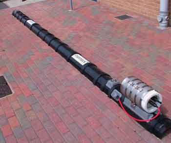 |
Fig. 5. A full-sized test version of the mat.
|
|
The fiber optic cable is laid out in the middle of the laminate in a continuous loop, so as to place the sensors in accordance with the required geometric layout. Two separate fibers are laid, each identical but separated by about 1/4 in. (6 mm). Both ends of each fiber exit through the garage. At one end, a composite base structure is incorporated for mounting the pressure container housing the electro-optical hardware (FSI enclosure).
A biaxial (+/ – 45) epoxy e-glass lay-up was selected to minimize the mat's longitudinal stiffness. The purpose was to have minimal effect on the riser pipe stiffness, but, on the other hand, maintain its relative torsional and 90° stiffness in the area of the sensors.
Redundancy. The fiber optic cables and sensors are positioned mid-laminate to provide maximum protection from impact damage and, beneficially, to reduce the potential of effects of local stress. Three sensor locations and two entirely separate, parallel circuits provide redundancy against manufacturing and subsequent, possible mechanical handling damage. The interrogator can look down both ends of a circuit, allowing it to handle one break
END EFFECTS
The embedded sensors are used to determine the mat's curvature, from which the pipe curvature is determined. In any given plane, three sensors are required to determine the curvature in two orthogonal directions. The sensors measure the strain in the axial direction and are placed in a fixed geometry relative to each other. At the mat's ends, the axial strain in the mat will not be consistent with the curvatures. The axial strain at the axial extremities of the mat will be zero. Moving in from this point, the strain increases until it reaches a level consistent with measuring the mat and pipe curvatures. As a generic guide, a factor of two pipeline diameters is sufficient to define the extent of this end effect for a standard mat and standard strapping. This guide results from FEA analysis of examples of typical laminates, dimensions and strapping arrangements that indicated a possible interference at distances of up to 1.3 times the diameter, Fig. 6.
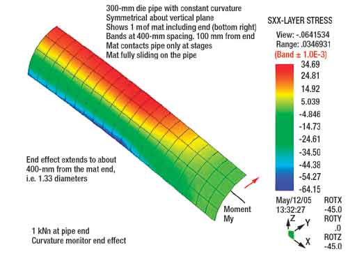 |
Fig. 6. Measurement of end effects.
|
|
FIBEROPTIC HANDLING/ SURFACE EMISSION
The fiber optic cable is brought through the laminate surface into a pressure connector.
Pressure testing. The mat and attendant hardware were pressure cycled to 270 bar in the Stress Engineering Houston facility without any detrimental effects. The strain readings of all sensors decreased as the pressure was increased, due to bulk compression of the mat. No creep was observed over the 19-hr dwell at pressure, confirming a good bond between the fiber optic sensors and the surrounding laminate.
System validation/ strapping procedures. Laboratory test and measurement programs were carried out by mounting the mat on a representative steel pipe in a four-point bend configuration. Known loads were applied, and actual and theoretical deflections were compared with the mat's output. Excellent agreement was obtained at typical load levels. Tests were conducted for a variety of mat orientations, confirming excellent performance in all bending orientations. The tests included investigation into various strapping densities that showed a remarkable tolerance to missing straps and to strap tightness.
Resolution testing. Ultimate system resolution was checked to determine the smallest change in curvature that can be detected. Loads were applied while the mat was monitored. A 0.5-kg load was applied to the pipe and removed, as was a 1-kg load. This process was repeated, increasing in 0.5-kg loads each time to a total of 4 kg. Data from each sensor were acquired at 10 Hz, Fig. 7.
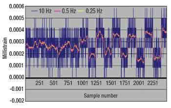 |
Fig. 7. Ultimate resolution of the system was checked with data acquired at 10 Hz.
|
|
Data acquired at 10 Hz were averaged using a moving window filter to generate data with a frequency response of 0.5 Hz and 0.25 Hz. Loading (compressive strain change) and unloading (tensile strain change) are resolvable for the raw 10-Hz data for the last five load cases (2-kg minimum detectable load, circa sample number 1,200) corresponding to a resolution of 1.4 microstrain or 70-km bend radius. Filtered data at 0.25Hz clearly resolve the loading and unloading of the 1-kg mass (circa sample number 600) corresponding to a strain resolution (minimum detectable) of 0.6 micro strain, equivalent to a 165-km bend radius.
DEPLOYMENT AND RESULTS
Following mat performance testing and system integration testing with other monitoring hardware and the data acquisition systems, the mat was deployed in July 2004 for BP on Thunder Horse field in the GOM. The mat was deployed at the bottom of the riser on the first joint, just above the Taper Stress Joint, which was at about a 6,000-ft water depth. The mat was strapped onto the riser while the pipe was vertical in the drill tower. Steel bands fastened the mat at several locations along its length. The riser joint was then lowered through the moon pool as further joints were added.
Data from the riser were sent in real time to the surface via an electrical umbilical. A topsides computer calculated fatigue accumulation and damage rate. The system has been deployed more than six times, monitoring the riser continuously while deployed. When the riser is retrieved, the mat is un-strapped and stored for the next deployment. Mat data have provided the operator with confidence in the fatigue accumulation of the critical riser joint.
DATA PRESENTATION
Since the mats measure strain directly, very little data processing is required to convert measured data to presentable information, such as stress or fatigue. Data can, therefore, be displayed in real time in the operating room, providing continuous feedback on riser loads.
Typically, a graphical user interface displays the magnitude and direction of the resulting bending, accumulated fatigue and remaining life at the current damage rate. The operating room display aims to provide only essential information required to make operational decisions based on measurements. Measurements are also streamed into a database for storage and more detailed event analysis. For this application, data were presented in real time in their simplest form as the accumulative fatigue percentage. The current fatigue wear rate was expressed in days of remaining life.
CONCLUSIONS
This first shape-sensing mat was designed, built, tested and successfully deployed in four months. Its deployment was straightforward. Requiring no specialized on-board processes, it did not affect or slow down riser deployment. The mat has subsequently proven to be highly reliable, providing ongoing strain analysis data to the client. Since this first deployment, further mats have been supplied, and orders are outstanding for several more.
Mats may be produced in various sizes and shapes to suit many structures, including tapered joints and welded pipes. The concept may also be extended to monitoring longer sections of risers or flowlines to verify locations of fatigue hot spots.
The composite mat has demonstrated that it provides a reliable host structure to armor and protect the fiber optic sensor network, and is suitable for deep-sea operations. The mat also establishes and maintains a structure that holds individual sensors in defined, relative positions permitting the use of combinations of sensors to provide various resultant data – in this case bend data, but in other cases, torsion, axial and hoop strains. The ability to mold the FRP mat to fit complex structures also allows fitting to non-linear items, such as taper joints. Such non-linearity can also be used to advantage, as it can provide a natural locking mechanism for the mat. Correct design and selection of the FRP layout can provide strain amplification for enhanced accuracies or, conversely, in areas of extreme strain, e.g., buckle, the composite can be designed to have less strain.
The small size and low power requirements of the optical interrogation hardware permit ready subsea deployment in pressure bottles, most readily as an integral unit with the mat. Thus, only power and communications are needed, and these can be readily provided through umbilicals or data and battery packs. The self-contained mat can be mechanically retrofitted by ROV or diver. 
ACKNOWLEDGEMENT
The authors would like to thank BP Exploration for permission to publish this article, which was originally presented as OTC paper 17951 at the 2006 Offshore Technology Conference, held May 1 – 4 in Houston.
THE AUTHORS
|
| |
Damon Roberts is a founder and engineering vice president of Insensys Ltd. He became involved in the fiber optic sensing technology while designing and building large advanced composite structures and appreciated the need for reliable consistent strain monitoring technology. Roberts pioneered the development of fiber optic sensing systems and has over 10 years experience in the field.
|
|
| |
Dr. Thanos Moros is a chartered mechanical engineer with extensive expertise in the areas of subsea floating and riser systems, fluid transport, and safety engineering. He is the URF engineering manager for BP's Deep Water Angola program. Over the years, Dr. Moros has worked on many aspects of Facilities Engineering. He has been involved in the coordination of various industry forums and JIPs in Europe and the US, and has published over 35 technical papers in journals and conferences. He earned a PhD in engineering from the University of Cambridge in the UK.
|
| |
|
|

