Artificial Lift
What’s new in artificial lift
Part 2 – Fourteen downhole and surface system developments from 11 companies for electric submersible pumping and other artificial lift related operations.
James F. Lea, Mewbourne School of Petroleum and Geological Engineering, Oklahoma University; Herald W. Winkler, Texas Tech University; and Robert E. Snyder, Consultant
Part 1, presented last month, covered 20 recent developments from 10 companies in three categories of artificial lift technology: sucker rod and Progressing Cavity Pumping (PCP) and plunger lift.
This concluding article introduces and updates 13 artificial lift developments from 11 companies, plus a review of an ongoing related project. Four of the presentations include new downhole and surface equipment for ESP systems. The remaining 10 items cover miscellaneous contributions for new downhole pumps, operations monitoring/ control, related downhole equipment, and deliquifying chemicals.
ELECTRIC SUBMERSIBLE PUMPS (ESPs)
Described here are four new systems for: an extreme temperature ESP; two downhole sensor/ monitors; and a novel diaphragm ESP.
ESP for extreme temperatures. Baker Hughes Centrilift, Claremore, Oklahoma, has developed an extreme temperature system for Steam Assisted Gravity Drainage (SAGD) tar sand applications, Fig. 1. Production from tar-sands in Canada is growing dramatically; however, SAGD systems – two directionally drilled, stacked horizontal wellbores with the top for steam injection, the bottom to produce the melted tar – severely challenge conventional ESP technology, due to extreme temperatures and temperature cycling.
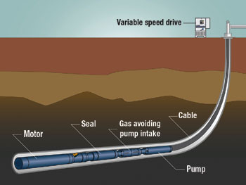 |
Fig. 1. The extreme temperature ESP system is designed for applications such as SAGD projects to recover tar sand oil.
|
|
To overcome these challenges, Centrilift minimized system elastomers; strengthened electrical connections and insulation; designed components for axial and radial thermal growth; and allowed for extra oil expansion. The SAGD environment test facility, a high-temperature, closed loop, allows for 18-day cyclic temperature testing of the ESP system to: fluid temperatures exceeding 500°F (260°C), pressures to 1,000 psi (6,900 kPa), and maximum flow to 27,800 bpd (50 l/s).
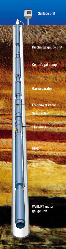 |
Fig. 2. Downhole WellLIFT sensor is designed for a broader range of measurements. Combined with WellLINK, it helps optimize run life.
|
|
A key consideration in the extreme-temperature design is reducing overall rig time, to achieve earliest production. The seal section and motor are pre-assembled, prior to shipment, saving time during installation. The extreme-temperature, plug-in pothead vs. a tape-in design, minimizes field splice time during installation.
Primary design features of the system include, for the: 1) Motor – special internal metallurgy to withstand demanding downhole conditions; 2) Seal section – early testing indicated need for improved thrust/ journal bearings, shaft seals and expansion chambers. Due to the elastomer, the seal is the most challenging design component for extreme temperatures; 3) Pump – thermal cycling characteristics of SAGD operations required special design considerations, including metallurgies/ coatings to extend run life in abrasive/ corrosive conditions. Additional mechanical design was required to handle stage compression issues specific to SAGD applications; and 4) Motor lead extensions – SAGD testing indicated the design must mitigate thermal expansion; and a robust, severe-duty, 4-bolt plug-in pothead, combined with motor-lead cable featuring individually encapsulated phases inside capillary tubing, was developed.
ESP monitoring and automation. Baker Hughes Centrilift has introduced a new downhole sensor designed to provide a broader range of measurements aimed at optimizing ESP-system run life and enhancing production. The WellLIFT* sensor, Fig. 2, measures seven downhole parameters, including: intake pressure; fluid temperature; motor-winding temperature; gauge electronics temperature and vibration on both X and Y axis; and discharge pressure and temperature. The system also tracks 17 surface/ diagnostic parameters, which allows high-level well management. Such costs can be further reduced by remote well monitoring and control through SCADA systems and via the Internet.
Centrilift also offers WellLink*, a comprehensive well-data distribution, retrieval and analysis service that provides data acquisition, display, control and analysis of ESP surface/ downhole systems. Well data can be accessed online with a standard web browser using the service.
WellLink features the following capabilities: 1) espGlobal* is a low-earth-orbit communication device for remote data acquisition and ESP system management. It works over any distance or terrain, providing two-way communication via one or more devices; 2) espVision* web-based monitoring system can be used with or without a SCADA system. Without, it provides an end to end, remotely hosted system accessible through a secure web log-in, offering the advantage of SCADA without the support/ maintenance. With SCADA, it provides real-time data collection/ characterization via the internet or private network connection.
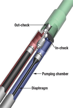 |
Fig. 3. Dual hose-like diaphragm, electric powered downhole hydraulic ESP.
|
|
And espExpert* is a real-time data analysis tool used exclusively by Centrilift engineers. It merges well data with AutographPC* proprietary ESP system sizing/ simulation software, to help understand downhole conditions and compare those to original system sizing, allowing experts to change well parameters or ESP performance to match well data via a user-friendly graphical interface.
Low Flow Hydraulic Diaphragm ESP. SmithLift, LLC, Provo, Utah, a division of Smith International, Inc., has developed and field proven the Hydraulic Diaphragm Electric Submersible Pump (HDESP). The pump is powered by a three phase, triple insulated electric motor and uses two hose-like “diaphragms” to positively displace formation fluid into the production tubing, Fig. 3. The pump was designed for low-production-rate (<200 bfpd) oil, gas and coal bed methane applications with depths less than 2,500 ft. This pump has undergone a thorough development and testing program since its introduction in World Oil May 2004, “What’s new in artificial lift,” Part 2. The pump offers operators numerous advantages over rod pumps, PCPs and centrifugal pumps.
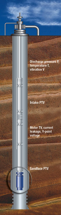 |
Fig. 4. Artificial lift downhole monitoring system for ESP.
|
|
Operators have reported production gains due to higher drawdown while avoiding problems associated with cavitation and gas locking. As the pumping mechanism is completely isolated from the well fluid, the pump can handle relatively more solids than conventional beam pumps and centrifugal ESPs that use small vane openings for low liquid volumes. Operators also report other advantages, such as: ease of installation due to the pump’s compact size (3¾-in. OD, 8-ft long, weighing less than 120 lb); a single integrated pump and high-efficiency electric motor; reduced electric power costs; pump-off tolerance; and decreased overall operating costs.
Artificial lift downhole monitoring. The Phoenix Select* monitoring tool from Schlumberger is the newest addition to Phoenix* artificial lift downhole monitoring systems. This cost-effective system features the latest generation of downhole sensors for in-depth diagnostics and analysis in wells and fields on artificial lift. By accurately identifying operating problems or anomalies in real time, it facilitates effective intervention strategies, protects lift systems, improves well integrity, and helps optimize production and maximize ultimate recovery.
The downhole systems can be used to monitor ESPs, beam (rod) pumps, PCPs, and gas lift systems. When monitoring an ESP, the sensor is connected to the pump motor; and the system transmits data to surface via the pump cable, Fig. 4. Monitoring options are: 1) Lite: Basic ESP monitoring and protection; 2) Standard: Adds discharge pressure, temperature and vibration for improved pump protection and performance analysis; 3) Advanced: Complete monitoring of both pump discharge and intake conditions; and 4) Reservoir: Extends pressure, temperature and vibration measurements to the sand face. This flexibility allows operators to select the appropriate level of monitoring for any artificial lift system.
Traditional monitoring applications require data sampled at higher rates; the new system adapts sampling rate for key downhole parameters so that sufficient data is available. Trip and alarm relays for all monitored parameters are field-programmable to match individual reservoir, well and operating conditions, thereby reducing false alarms. This reduces compatibility issues by using a single data acquisition/ communications platform for all monitored wells. The combination of advanced transducer technology, state-of-the-art microelectronic components and digital telemetry ensures reliable and accurate information.
Phoenix* monitoring systems are fully compatible with other monitoring/ control technology, enabling an integrated system comprising: a sensor unit, an integrated surface panel or universal site controller, a surface choke assembly, software for manual data retrieval, and an optional portable data collector. They are SCADA-ready, with a Modbus remote terminal-protocol port and RS232 and RS485 ports for continuous data output. Downhole and field components can be further integrated with the espWatcher* surveillance and control system for: real-time, remote data acquisition; alarms and alerts via satellite; remote pump startup and speed control; and remote resolution of a variety of pump problems.
MISCELLANEOUS
Ten items under this category include: a subsea jet pump, a paraffin protection tool, gas well software analysis, deliquifying foamer, a downhole SCSSV tube bypass, wireless automation, an electronic flow meter, a capillary tube bottom running tool, what’s new with ALRDC, and a report from a consulting engineer on tubing flow control progress.
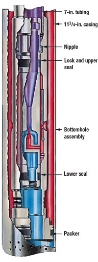 |
Fig. 5. Basic design of wireline-installed subsea jet pump for 7-in. tubing.
|
|
Planned subsea jet pump. Weatherford, Houston, has designed and manufactured a special wireline-installed 7-in. subsea jet pump, currently planned to be installed for offshore operator, Lundin, in late December 2006, or early January 2007. The operator is drilling the well about 100 mi off the coast of Tunisia in 820-ft water. The subsea completion will include 11¾-in. casing and 7-in. tubing. The well is expected to produce in the range of 20,000 bpd.
Lundin recognized up front that cost for intervention after the well is put on production would be prohibitive. Therefore, it commissioned a study by another company to determine the best method of artificial lift. That study determined jet pumping to be the best choice. Weatherford was then contacted by Lundin and, in response, proposed a 7-in. wireline jet pump. While a 5-in. pump would handle expected production, the larger size was selected to minimize fluid velocities inside the pump for the longest run time. The special jet pump, as illustrated in Fig. 5, was designed and manufactured for installation as noted.
The initial power-fluid rate of the wireline-installed pump in the 7-in. tubing will be about 13,500 to 15,000 bpd, depending on reservoir response. Lundin plans to use water, but that is open to change. Initial injection pressure will be about 3,500 psi and will be limited to 4,800 psi as watercut increases; initial watercut is expected to be 1.0%. This is believed to be the first subsea jet pump installation. And a 7-in. jet pump is rare. The only other one known to exist was in Oman long ago, reportedly producing 50,000 bpd. The expected 20,000 bpd will likely decline over time, with increasing watercut and the injection pressure limit of 4,800 psi. The gas oil ratio is only 25:1, so gas is not an issue. If it were, the throat would be sized to accommodate any free gas at the pump.
Downhole paraffin protection tool. Para Service Inc., Calgary, Alberta, manufacturers Enercat*, a downhole tool used for prevention and removal of scale, paraffin and asphaltine deposition in oil/ gas production. When installed in a producing oil or gas well, current treatment methods such as wireline scraping, chemical and hot oil circulation, can be eliminated. The tool, which has been used successfully since 1993, comprises a 4-ft tubing pup joint, with a jacket containing a solid-state quartz compound. The crystals are encased in molten aluminum and formed into a mold that can be attached to a tubing pup joint. The quartz crystals and semi-precious metals, create a vibrational energy to stabilize the original micelle structure to prevent paraffin from turning into solid form, thus allowing the solution to move smoothly and cleanly through the pipe.
When crude oil flows into a wellbore, its pressure and temperature decrease. Paraffin and water then would be released from the water-in-oil emulsion, with the paraffin solidifying at the reduced temperature condition. Enercat provides a subtle vibrational energy, which stabilizes the water-in-oil emulsion structure and prevents paraffin release from the micelle structure to form solid states.
Simple to install on the tubing, tools can be installed either below the pump intake or above the pump discharge, or as a tail joint at the end of the tubing. Installed in the oil well before oil reaches the pump, the tool’s subtle energy will structure the molecule-bonded water to become more stable, enabling it to resist temperature drops to below the normal solidification point; it also resists pressure changes. In turn, the tool will deliver oil to surface in close to formation condition.
The tool requires no external power source, maintenance or servicing, and has no internal restrictions. It works in virtually any well that experiences deposition, including dual completions, directional, horizontal, SAGD, water source and water injection wells. It works with any pumping system, with the exception of ESPs. Each application is designed for the specific well, depending on tubing size and fluid volume.
Software for flowing gas well acoustic pressure survey. Until now, most acoustic fluid level surveys in gas wells have been done successfully in static wells, with the objective of determining static reservoir pressure. Recent hardware/ software developments in digital Acoustic Fluid Level Technology by Echometer Co., Wichita Falls, Texas, have resulted in being able to undertake not only static bottomhole pressure calculations from fluid level measurements, but extend this technology to flowing pressure gradient surveys in gas wells. The new procedure involves monitoring fluid level and pressure in the tubing during a short-term test sequence. The procedure is inexpensive and non-intrusive.
These tests are designed to determine which flowing gradient conditions exist in a well by performing a series of fluid-level and surface-pressure measurements while flow at surface is stopped for a time sufficient to identify behavior and distribution of fluids in the flow string. Test duration is typically on the order of 20 to 30 min. Advantages over wireline flowing pressure surveys include lower costs and risks (safety and potential remedial operations) since it is not necessary to introduce measurement tools in a flowing well.
Fig. 6. shows typical results from one such survey. On the left is a schematic of the wellbore showing distribution of flowing gas and liquid, and measured/ calculated pressures, gas flowrate and liquid fractions. On the right is the corresponding flowing tubing pressure traverse in relation to static reservoir pressure. Knowledge of flowing gradient and fluid distribution in the well is important in determining whether inflow from the formation is being restricted by excessive liquid in the flow string, thus requiring application of some deliquifying technique such as installation of plungers, pumps, or redesign of the flow string to increase gas velocity.
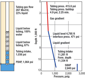 |
Fig. 6. Analysis of acoustic fluid level survey in flowing gas well.
|
|
Chemicals for deliquifying gas wells. There are several methods to increase gas production through artificial lift to remove liquids from a gas well, including mechanical and chemical applications. Multi-Chem Production Chemicals, San Angelo, Texas, says , to effectively create a foam to artificially lift the produced liquids from the wellbore, it is necessary to have three components: water, foaming agent and agitation. The company has formulated new products that include over 70 foaming agents and combination foaming agents, generally under the Multi-Chem* trademark. Creation of foaming agents that are compatible with: paraffin dispersants, H2S scavengers, corrosion inhibitors, scale inhibitors and salt dispersants, and that perform in different levels of chlorides, are the types of improvements.
The first step in achieving a successful foaming-agent-assisted lift program is proper selection of candidate wells. The most common observed signs of liquid loading include: erratic production of gas and liquids, premature production decline, lost-time production, and/or wells requiring operator intervention. Once downhole scale and/or salt deposition possibilities have been eliminated, data gathering for a foaming agent lift program must be completed. But not every well is a candidate for liquid foaming. If a well has inadequate BHP to produce fluid volumes that foaming is designed to achieve, then mechanical artificial lift or gas lift is required. Next, the right foaming agent quality and additive selection should help remove liquids that enter the gas well on a daily basis. This is done by primarily using foam to reduce liquid density.
The third step in achieving a successful foaming agent assisted lift program is proper application. The most common methods of application are: 1) annular injection; 2) use of a capillary string; 3) use of coil tubing injection; 4) tubing pump injection; and 5) annular or tubing batch injection. Of course, it is well known that solid chemicals are introduced using soap sticks in many wells in the industry.
Another key to a successful foam-assisted-lift program is effective monitoring of the foaming applications. Accurate performance history must be kept, and communications between operations and suppliers maintained at all times. Multi-Chem company indicates successful use of a liquid foamer to deliquify a gas well, will return an average $9.00 for every $1.00 spent on chemicals. In summary, use of foamers can be considered a chemical method of artificial lift which lowers the liquid density and interfacial tension between gas and liquid, allowing the well’s energy to more efficiently lift liquids so gas can flow.
Subsurface safety valve with capillary bypass. Safety and protection of the environment are prime directives in the offshore oil industry. As reservoirs in the Gulf of Mexico become “brown fields,” new technologies must be developed for operators to maintain production rates. And, if that technology increases production, extends well life, increases recoverable reserves, and keeps people safe and the environment clean, all at a bargain price – a paradigm shift in artificial lift begins. Introduced here is such an emerging technology that combines two well known yet dissimilar technologies: capillary tube completions and surface controlled subsurface safety valves (SCSSVs). The technology is the result of joint development by two companies: Dyna-Coil of Kilgore, Texas and Tejas Research and Engineering of The Woodlands, Texas. The InjectSafe* SCSSV and Capillary Tube Completion System, Fig. 7, employs the world’s first subsurface safety valve that enhances production by increasing total recoverable reserves (by as much as 10 to 15%) while not compromising well safety.
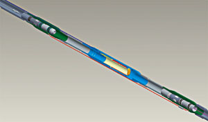 |
Fig. 7. Cutaway of the subsurface safety valve solution and capillary tube connectivity (Patents pending).
|
|
A majority of offshore wells employ SCSSVs – certainly all GoM wells regulated by the MMS. Also included are sour-gas land wells near populated/ environmentally sensitive areas. SCSSVs, while critically necessary, pose mechanical and regulatory obstacles during well remediation. InjectSafe is a simple system of economically injecting specialty chemicals in a well. This is accomplished by deploying a capillary string inside the production tubing, providing a bypass through or around the SCSSV, and providing a path to a location deep in the well. Injecting chemicals increases production by: 1) use of surfactants or foamers for deliquification in gas wells; 2) inhibiting precipitate accumulation in tubing and SCSSV, e.g.: salts, asphaltenes, paraffin, hydrates, scale and diamonoids; 3) inhibiting tubular corrosion; 4) injecting de-emulsifiers at the perforations; and 5) sweetening sour fluids.
InjectSafe offers well treatment choices previously not available. Installation of the capillary chemical injection system is predicted to enable production increases by applying a variety of treatments, as noted. Reliability of the SCSSV also benefits from continual injection of chemicals, where corrosives and precipitates in the form of scale, salts, paraffin and asphaltines, can accumulate in the valve’s operating mechanism. Such accumulations impede proper closure, which can lead to non-failsafe conditions and potential failure. Using the new system, a cocktail of fluids can be injected to solve a variety of wellbore production challenges.
Wireless automation technology. Ferguson Beauregard, Tyler, Texas, offers the latest in wireless automation technology with its DigXtend* family of I/O products, which replaces the point-to-point wire and conduit systems generally utilized in control system installations. Production can be centrally managed by using the Wireless I/O Adapter (WIO/A) for collecting and transmitting process information located up to 1 mi (line-of-site) from the centralized Wireless I/O Data Concentrator (WIO/DC).
The system utilizes non-licensed 900-MHz or 2.4-GHz frequency hopping spread spectrum radios and is configurable for various applications. An enhanced version of the product will soon be available. It supports up to 12 slaves (WIO/A) reporting to a single data concentrator (WIO/DC) with 1-sec. refresh. Each WIO/A supports up to five analog inputs (one dedicated for battery), four digital inputs, two pulse accumulator inputs, and eight digital outputs. The WIO/DC is routinely polled for data by the RTU5000 (or other third-party devices) via a serial connection using Modicon Modbus RTU (slave). DigXtend applications include wireless tank-level measurement, compressor monitoring, flow meters, status alarming, and more.
Gas flow meter. The EFM3000* is Ferguson Beauregard’s low-powered, economical and dependable electronic gas flow meter, Fig. 8. The foundation of its design incorporates the highly-accurate Emerson-Rosemont dual-variable 205 pressure sensor, with options for static pressure to 3,626 psia and differential pressure to 1,000 in. water, each with 10:1 range down with accuracy of ±0.075% of span. The rigorous standards of API Chapter 21 and AGA 3 & 8 have been applied to meet the most demanding applications for measurement, including 35 days of production logs, 275 events and 300 alarms.
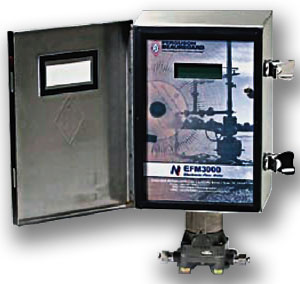 |
Fig. 8. Electronic gas flow meter.
|
|
The EFM 3000 is configurable as Modbus ASCII or Modbus RTU protocol. Two onboard communication ports are standard – RS232 and RS232/RS485. Communications options include spread spectrum and licensed radio systems and satellite modems. A built-in communications sleep mode helps extend the autonomy of EFM3000. The EFMaintainer* configuration utility is a user-friendly Microsoft Windows application for maintenance and reporting of the EFM3000.
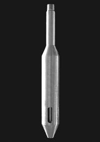 |
Fig. 9. Bottom tool with pump-out plug for running capillary tubing strings.
|
|
Running tool for capillary tubing CT. VortexFlow, LLC, Denver, Colorado, has developed the new Bullnose Tool* for use in CT applications. It seals the end of a CT string so that it can be run safely in a live well, Fig. 9. When the CT is landed, the plug from the tool is pumped out and the string is live with the tool in place. The tools have been run successfully in nearly 100 shallow wells in Canada.
VortexFlow also produces downhole equipment that establishes a helical flow pattern in production tubing. This flow regime has been shown to reduce the energy required to transport multi-phase fluids to surface and delay need for deliquification techniques that require external energy input. Depending on the application, the tools can be: installed on the end of conventional tubing (DX); threaded on the tubing (DXI); or set in a seating nipple or collar stop (DXR).
Artificial lift council. The Artificial Lift R&D Council (ALRDC) is a non-profit, 501(c)6 organization created to share information, promote best practices, and facilitate research and development in artificial lift. ALRDC provides:
- Assistance to API and ISO technical committees working to develop AL standards and recommended practices
- An AL Q&A section where people can submit questions about AL matters and receive answers from a panel of experts
- Sections for sharing best practices, case histories and forums
- Industry catalogs and AL computer programs that can be accessed, some for free and some for a trial basis
- A job matching service
- Special seminars focused on specific AL topics (a recent seminar was on sucker rod pumping)
- Coordination of special AL continuing education courses – one on progressing cavity pumping was planned for April 2006 in Houston, and
- Coordination for AL R&D projects is available, where the project scope is larger than any one company wishes to carry.
A major ALRDC activity is to assist in coordinating artificial lift workshops. Currently, annual workshops are held on gas-lift (with ASME, API and ISO); and gas well deliquification and sucker rod pumping (with the Southwestern Petroleum Short Course). Bi-annual workshops are held on ESP and PCP (both sponsored by SPE). Membership in ALRDC is free and can be accessed from www.alrdc.com. Members can join a “news group” and receive information on current artificial lift activities.
Gas well tubing-flow controller. As reported by David A. Simpson, MuleShoe Engineering, Flora Vista, New Mexico, a combination of equipment and flow-control logic tubing flow controllers allow a well to flow tubing above some critical rate while producing “extra” gas from the tubing-casing annulus. These schemes have been used by several companies to deliquify gas wells for several years with varying success and poorly-reproducible results.
Most implementations have used differential measurement, i.e., either square-edged orifice or V-Cone measurement, to determine flow rate in the tubing, and pneumatic-controlled valves to control how much casing gas to produce. It seems that the delays inherent in a change in imposed backpressure vs. the position of a valve on the casing line causes positive-feedback within the wellbore system that makes the system inherently unstable. Added to that is the fact that it is very common for pneumatic valves to “hunt” for a precise position due to the compressible nature of the control gas.
A recent version by some in industry seems to have improved repeatability and predictability of this scheme. They have substituted “pitot tube” flow measurement for the tubing flow and an electric-driven control valve on the tubing. In this configuration, there is no measurable pressure drop across the measurement device and (more important) changes in flow rate are not accompanied by an excessive change in the well’s backpressure. The electric-driven control valve has a very linear response to the input signal and a precise positioning mechanism that does not tend to “hunt.”
The control logic in this version allows the casing control valve to flow as long as tubing flow is at least equal to some pre-determined critical rate. Since many wells have significantly lower gas-gathering pressure than their water-gathering pressure, the logic also allows the system to maintain a minimum casing pressure – which allows the casing pressure to be used to drive a “blow case” on the separator to force water into the water system without need to maintain an artificially high backpressure on the separator. 
|
THE AUTHORS
|
 |
James F. Lea is the Kerr McGee professor, Mewbourne School of Petroleum and Geological Engineering at Oklahoma University. He holds BS/MS degrees in ME from the University of Arkansas, and a PhD in ME from Southern Methodist University. Lea worked for Sun Oil Co. as a research engineer from 1970 – 1975, taught at the University of Arkansas from 1975 – 1978, was team leader of production optimization and artificial lift at Amoco EPTG from 1979 – 1999; was chairman of the PE Department of Texas Tech from 1999 – 2006, and recently assumed his present position at the University of Oklahoma. Lea is a registered professional engineer, and has authored several patents and many publications related to production and artificial lift. He received the SPE Production Award, has been SPE Distinguished Lecturer twice and received the Slonneger Award from the SWPSC.
|
|
 |
Herald W. Winkler is former chairman, now professor emeritus and research associate, in the Department of Petroleum Engineering at Texas Tech University in Lubbock, Texas. He is presently working as a consultant in artificial lift, specializing in gas lift.
|
|
 |
Robert E. Snyder, consultant, recently retired from Gulf Publishing Co. (GPC). He earned a BS degree in mechanical engineering from the University of Wyoming in 1957. Snyder served two years in the U.S. Air Force, worked 10 years for Marathon Oil Co., GPC for 29 years, and Completion Technology Co. for seven years. Within GPC, he served as engineering editor, editor of Ocean Industry and World Oil. He has co-authored several patents, authored many technical articles and made numerous technical presentations.
|
|
|

