Offshore Report
Magnolia field’s trapped annulus pressure solved
Multiple solutions overcame a serious problem in the GOM deepwater development.
L. F. Eaton and W. R. Reinhardt, ConocoPhillips, Houston; J. S. Bennett, Devon Energy Corp., Houston
ConocoPhillips is developing the Magnolia field at Garden Banks block 783 in the Gulf of Mexico with a Tension Leg Platform (TLP) in 4,674 ft of water. The field features six oil wells with rates as high as 25,000 bpd and two gas condensate wells with peak rates of 75MMcfd and 15,000 bpd. The wells are completed with dry trees.
Magnolia’s wells were pre-drilled in 2002 and 2003.1,2 After installing the TLP in August 2004, a 2,000 hp platform rig, MODS 201, was installed to complete eight wells. The last and eighth well required drilling the production interval to total depth (TD).
Following installation of the platform rig, two 11.75 in. OD production risers were installed. The first two wells were then completed to begin production. The remaining six production risers were run in a batch program, followed by completing the remaining pre-drilled wells. First production occurred December 12, 2004.
Completion designs for the wells were developed during a two-year planning period from 2002 to 2004 with final detailed planning completed July 2004. During final completion planning in early 2004, the team identified two intermediate drilling liners without cement across the liner lap. The two wells had annuli that could potentially collapse under production conditions.
COMPLETION DESIGN
A 36 x 20 x 13.625 x 10.75-in. casing program was used to drill the development wells. The 10.75 in. casing string was run as a liner to minimize the equivalent circulating density while drilling to TD. After the 8.062 in. production liner was run across the producing reservoirs, the 10.75 in. liner was tied back to the subsea wellhead prior to temporary abandoning the well.
The typical casing program results in 9.5 in. ID drift from surface to the top of the production liner, and 6.5-in. ID drift through the producing interval. The two exceptions are the A8 well, with 10.75-in. OD casing and 9.5-in. ID drift, and the A9 well with 10.375-in. OD casing and 8.5-in. ID drift across the productive interval. The casing program at Magnolia addresses reservoir compaction loads and potential annular pressure buildup. Thick-wall tubulars were used for the 10.75-in. intermediate string, the 10.75-in. tie-back string, and the 8.062-in. production liners set across the reservoir.
The Magnolia field contains Pleistocene. Pliocene and Miocene Age stacked turbidite reservoirs. The primary pay horizon is the B-25, a coarse Pleistocene siltstone. It has highly laminated sequences and large gross thicknesses. Perforation intervals range from 110 ft to 571 ft.
The completion design needed to provide effective sand control to prevent erosion damage to the surface facilities, while producing enough oil and gas to meet project economics. The long perforation intervals and laminated sands necessitated high-rate frac-packs and gravel pack screens with alternate path technology for sand control. Six completions use single, fractured and gravel packed (frac-pack) completions; one uses a single, selective frac-pack and one has stacked, commingled frac-packs.
The tapered tubing string consists of 3.5-in. OD tubing inside the 6.5-in ID drift casing and 4.5-in. OD tubing inside the 9.5-in. ID drift casing. The production packer was set above any potential through-tubing completions above the gravel pack packer. A Downhole Pressure and Temperature Gauge (DHPTG) was placed above the production packer for reservoir monitoring.
A Mud Line Pack-Off Tubing Hanger (MLPOTH) was set 300 ft to 350 ft below the mud line to isolate the casing annulus from the 11.75-in., single barrier, production riser. A second DHPTG was placed below the MLPOTH to monitor annular pressure buildup during production.
A Gas Lift Mandrel (GLM) was run 300 ft to 350 ft below the MLPOTH, then the riser x tubing annulus was displaced with nitrogen. Nitrogen is placed in the riser annulus above the mudline as low-conductive insulation for flow assurance.
Once the riser tubing annulus was displaced with nitrogen, a gas lift dummy was installed into the mandrel and the nitrogen pressure bled to 50 psi. This design reduces the hydrostatic pressure at the 10.75-in. tieback, since the GLM depth is positioned at about 5,500 ft. Hydrostatic pressure reduction increases the collapse load on the production casing string.
The completion brine left in the tubing x casing annulus expands as the well heats during production. The 300-ft to 350-ft nitrogen cushion below the MLPOTH allows for this expansion. The flowing mud line temperatures range from 50°F to 145°F.
POTENTIAL PROBLEM WELLS
The upper portion of the production casing was the same on all wells, a 10.75-in drilling liner tied-back to the mud line. The physical constraints of fitting a Polished Bore Receptacle (PBR) and liner tieback stem inside 12.25-in. ID while still allowing a 9.5-in. drift required a thin PBR wall section. This results in a PBR with much weaker collapse than burst ratings. Using high yield strength material increased the PBR’s burst rating, but the collapse rating could not be similarly increased.
Displacing the completion brine with low-pressure nitrogen reduced the internal pressure by about 3,400 psi and caused a potential collapse load on all the wells.
The last appraisal well, GB 783 A3 ST1, was also to be used as a development well. On this well, the 10.75-in. liner top packer set prematurely prior to the primary cement job, preventing cement placement into the liner lap. This was not thought to be a problem at the time. Prior to tying-back the well, an isolation packer was run to increase the burst rating of the liner top packer. However, the new liner top packer did not have a higher collapse rating than the PBR. The other potential problem well was GB 783 A8, the first development well drilled.
On the other six wells, cement was placed behind the PBR during the primary cement job or as the result of a liner top squeeze. This provided more reliable long-term annular isolation and increased the burst and collapse resistance of the liner lap. The bond of the cement to the casing helps prevent PBR collapse.4 Cement presence was determined by reversing out after the primary cement job. During the pre-drill wells, if lost circulation occurred while cementing the liner prior to cement rising above the previous shoe, the liner lap was cement-squeezed. If no lost circulation occurred during the primary job the well was reverse circulated after setting the liner top packer, which verified cement returns.
During the pre-drill program, the bottom of the tieback stem was positioned while running the tieback string midway in the PBR. This was to balance two conflicting concerns. It was necessary for the seals on the tie-back stem to enter the PBR to isolate the 13.625-in. surface casing from production burst loads. However, if the tieback stem bottomed in the PBR, there was concern that the 10.75-in. tie-back string would not buckle enough to allow the subsea casing hanger to be landed in the wellhead. There was also concern about wear and burst load, if the string was in compression. The tieback was spaced out to have 8 ft to 10 ft of PBR below the bottom of the tieback stem. The tie-back stem was cemented to cover 1,000 ft of the annulus to prevent movement during production. The tie-back cement also acts as an annulus seal. The combination of the tie-back cement and the liner top packer could create a trapped annulus across the PBR.
The temperature gradient is low in the deepwater setting of Magnolia field. The predicted production rates would bring bottom hole static temperatures to the liner hanger tie-back. This could cause a 20°F temperature increase in the trapped liner lap.
MULTI-STRING ANNULUS MODELING
To determine whether there was a potential collapse problem, the drilling, completion, and the projected production history was modeled for the two potential problem wells. The specific data for each well was entered into the proprietary WellCat program.
The program output included the loads and temperature profile of the well for both the “as-cemented” and production case for each casing string. The thermal results were then used to predict the annular pressure build-up within trapped annuli as the well was put on production.
The predicted temperatures and pressures were used in the program’s tubular stress model to determine stresses for each of the casing strings in both wells. Analyses revealed that the two tie-back receptacles in the A3 STI well and the single tie-back receptacle in the A8 well were subjected to excess collapse loads, Fig. 1.
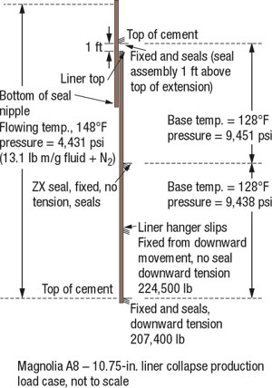 |
Fig. 1. This simplified well geometry and basic information was used for the FEA load case.
|
|
FINITE ELEMENT ANALYSIS
Up to this point, the analysis of the collapse potential of the liner hanger and tieback receptacle was based on API formulas. However, API formulas are most accurate for long, unsupported tubulars, not short members that are supported on each end, as with the liner tie-back string stung into the PBR. A FEA was used to better understand the system’s collapse properties. An outside consulting firm performed this analysis using multiple iterations.
The exact geometry of the liner casing, liner hanger, liner hanger packer, PBR, tieback stem, and tieback casing was obtained along with the measured material properties. This information was used to develop a FEA model based on as-installed properties versus nominal properties. This more accurately predicted the location of the collapse and its severity in the assembly, Fig. 2.
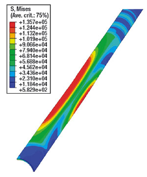 |
Fig. 2. Analysis showed that the liner hanger PBR would collapse from pressure differentials.
|
|
The initial FEA revealed that there were multiple weak points and that the collapse initiation pressure was higher than predicted by API formulas, Table 1. The PBR extension had the lowest FEA predicted collapse pressure at 4,900 psi. The next lowest predicted collapse was 5,900 psi in the packer body around the thread region. The packer body below the liner lap, which extends for approximately 40 ft, had a predicted collapse pressure of 6,720 psi.
| TABLE 1. The initial FEA results. |
 |
|
Analysis of tie-back string casing tallies suggested that the unsupported length of the PBR from tie-back stem to liner hanger body was 9.75 ft. Two additional models were run that examined this length plus and minus two feet (7.75 ft and 11.75 ft). The results showed no substantial collapse difference between the 9.75-ft and 11.75-foot lengths. The 7.75-ft model predicted a collapse pressure about 200 psi less than the 9.75-ft model.
The amount of fluid expansion in the trapped annulus was limited based upon the trapped volume and the predicted temperature change. Prior to the analysis, one uncertainty was the deformation at the collapse pressure. The question was whether the annulus pressure would drop below the collapse extension pressure prior to a collapsing member contacting the tubing string. The reduction in trapped annulus pressure as the PBR collapsed was modeled. Analysis revealed that the PBR would not stop collapsing until after it contacted the tubing string, a worst case, Fig. 3.
 |
Fig. 3. Finite element analysis revealed that the PBR would not stop collapsing until after it contacted the tubing string.
|
|
POTENTIAL SOLUTIONS
Several sessions were held with Magnolia’s completion engineering personnel to identify potential solutions. All of the solutions had some negative facet. Five solutions were identified:
Run a scab liner across the tieback. This would result in cement and an additional casing string across the PBR and would produce the highest collapse rating. The A8 completion was to be placed in 9.5-in. ID. Running the scab liner prior to performing the completion would prevent setting the sump and production packers. An uphole recompletion in the 10.75-in. casing was planned for later in the well’s life. The scab liner would prevent setting sump or production packers in the casing for the recompletion. If the scab liner covered the entire 10.75-in. casing interval, two strings of casing would have to be perforated.
The scab liner was thought to be acceptable if the sump packer was installed, the well perforated, the sand control screens run and the well frac-packed prior to running the scab liner. The downside to the solution was that, if the well experienced a sand control failure, the gravel pack packer could not be pulled through the scab liner. This would prevent a workover, which was an unacceptable risk.
Install a short expandable sleeve with two different wall thicknesses. One of the prominent expandable casing suppliers proposed this solution. The thick section would cover the 11-in. ID PBR, the section would bond to the tie-back stem and liner hanger and still leave a 9.5-in. drift. While potentially meeting the requirements, the expandable patch was a new design that had never been prototype or field tested and would require precision placement. The possibility of setting the patch in an improper location or not setting it correctly was thought to be high. This solution was abandoned.
Perforate the PBR to equalize pressures. This simple solution would rely on the liner top packer to provide an annulus seal between the 13.625-in. x 10.75-in. casing annulus. If the liner top packer leaked, the uncemented sands below the 13.625-in. shoe would be able to pressurize the production tubing x production casing annulus with gas. The only way to solve a leaking liner top packer would be to pull the completion. This solution was rejected.
Follow perforation with a cement squeeze. A variation of perforating the PBR was to follow the PBR perforation with a cement squeeze into the void area. While this solution would work if the liner top packer leaked, the packer was expected to hold, since it had been successfully pressure tested during drilling of the well.
Place heavy brine in the annulus. The selected solution was to place 17.8 lbm/gal ZnBr2 brine in the annulus from the mud line down to the production packer. This would increase the internal pressure, thus reducing the net collapse load to a value below the collapse rating of the PBR. The maximum expected differential collapse load once ZnBr2 was placed in the well would be approximately 3,800 psi versus the 4,900 psi FEA-determined PBR collapse rating. This solution required that the production packer and tubing components be compatible with ZnBr2 brine.
Potential tubing corrosion and a hole in the tubing would allow the brine to u-tube into the tubing and lower the brine level until the PBR collapse rating was exceeded. The brine would also need to be circulated out of the well prior to a workover. While the heavy brine solution had drawbacks, it was less risky than the other solutions and was chosen for the A8 well.
EQUIPMENT MODIFICATIONS
The heavy weight brines considered as packer fluids were ZnBr2 and potassium cesium formate. ZnBr2 was deemed the most economical solution, but elastomer compatibility, corrosion, and safety issues had to be addressed.
To qualify ZnBr2, multiple issues were investigated and some required design modification. ZnBr2 was not compatible with the nitrile elements of the production packer or the nitrile elastomers in the annulus circulating valve (ACV). A redesign of the production packer element and subsequent ISO 14310, VO requirement testing, were conducted and completed within three months. The nitrile elastomers of the ACV were replaced with viton. The MLPOTH also used nitrile elements. However, the risk of compatibility problems were mitigated by setting the MLPOTH prior to introducing ZnBr2 into the well and by stopping the displacement at a depth well below the MLPOTH.
Previous corrosion testing suggested that with the combination of the low bottom hole static temperature (138°F) and the application of appropriate inhibitors, corrosion would not be an issue with the production liner or the 13CR110 Hyp-1 tubing. Proper rig personnel training and brine exposure minimization addressed ZnBr2 handling issues.
A8 RESULTS
To ensure the modeling was correct prior to completing the well and because of increasing cost and well control risk, the PBR was exposed to the anticipated production collapse loads with a negative liner test. A hook wall packer was set above the liner PBR and the workstring displaced with base oil. This created a differential collapse pressure at the liner PBR of 3,812 psi, a value equivalent to the maximum collapse load expected during production. This test provided the confidence needed to proceed with the completion. The well was displaced to 13.0 lbm/gal CaBr2 completion fluid, perforated, and frac-packed.
Two uphole sands, the A-80 and B-10 sands, were targeted for future through tubing re-completions. An isolation assembly was installed to provide a sump, and a production wireline reentry guide was positioned 50 ft above the A-80 to allow casing access for the future perforating and sand control operations. This complicated the ZnBr2 displacement by introducing a large quantity of 13.0 lbm/gal CaBr2 completion fluid with the potential for intermixing with the ZnBr2 during the displacement. A minimum equivalent density of 16.7 lbm/gal was desired at the liner PBR to maintain a higher hydrostatic than had been tested in the negative test. A 17.8 lbm/gal ZnBr2 was selected based on mass balance, considering the volume of 13.0 lbm/gal fluid below the end of tubing and complete intermixing of the fluids during the displacement.
The production tubing, packer, ancillary equipment, and MLPOTH were run into the well and the tubing hanger landed. The MLPOTH was set and tested. A test plug was installed in the wireline lubricator and the lubricator tested to allow immediate deployment of the test plug, once the packer fluid was in place. The tubing casing annulus was displaced to 5,400 ft by pumping 540 bbl of 17.8 lbm/gal ZnBr2 followed by 189 bbl of 13.0 lbm/gal CaBr2 down the tubing taking returns through the ACV, through the riser, from the casing head and to the rig choke manifold. The final displacement pressure was 1,600 psi, which suggests an equivalent density of 17.0 lbm/gal in the annulus. The test plug was deployed with slickline, then the production packer was set and tested.
The tubing riser annulus was displaced by retrieving the dummy valve in the GLM at 5,523 ft, opening the ACV and pumping 78 bbl of 9.1 lbm/gal MEG-NaCl completion fluid, followed by nitrogen. Once the nitrogen was in place, the dummy valve was reinstalled and pressure tested. The nitrogen was bled back to 50 psi and the ACV closed, Fig. 4.
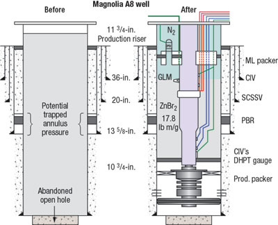 |
Fig. 4. A 17.8 lbm/gal ZnBr2 was selected to cover the potential trapped annulus pressure zone in the A8 well, left. A minimum equivalent density of 16.7 lbm/gal was desired at the liner PBR to maintain a higher hydrostatic than had been tested in the negative test, right.
|
|
The SCSSV was opened and the formation isolation valve was hydraulically cycled to allow the well to flow. The 9.1 lbm/gal MLG-NaCl brine provided an 800-psi underbalance to the bottom hole pressure. Care was taken during the flowback to capture the ZnBr2 interface at the gas lift mandrel and the end of tubing. The fluid was captured and returned to the supplier for reclamation with no spills or safety incidents.
The A8 well was slowly ramped to a peak rate of 75 MMcfd and 15,000 bpd of condensate. The maximum observed temperature to date at the gauge below the mud line is 127°F. The production rate has declined as anticipated; accordingly, the temperature below the mud line is also declining. The tie-back has withstood worst-case loads and has no well integrity issues.
A3 ST2 PLAN
The A3 and A3 ST1 wells were both drilled during the appraisal phase prior to project sanctioning. Since the project was not sanctioned, production casing was not run during appraisal drilling to minimize Capex. This dictated redrilling the producing interval with a second sidetrack and running 8.062-in. production liner. This opened the option to lap the weak liner top with additional production liner and squeeze the liner top for complete wellbore isolation from the weak 10.75-in. liner hanger and PBR.
Considerable reserves were booked to the A3 ST2 well and the well life will extend for several years. With the high-density annular fluid option, a tubing leak later in the well life from corrosion could cause a collapse of the PBR and the loss of the A3 ST2. Extending the production liner to cover the 10.75-in. liner top would avert the well loss possibility from a tubing leak.
The plan followed for the A3 ST2 well, was to run the tapered liner string to increase the collapse resistance across the liner hanger PBR. An 8.062 in. liner was run in open hole to provide greater compaction resistance than standard 7.625-in. casing. A tapered 8.062 x 7.625-in. liner string was run with 7.625-in. easing above the 10.75-in. shoe to above the liner hanger tieback. Extending the production liner top above the 10.75-in. PBR requires a longer interval of 3.5-in. tubing below the 4.5-in. tubing interval, Fig. 5. Analysis has shown this will have a negligible affect on the expected production rates or well recovery. The A3 ST2 well has been completed and has seen maximum production without a problem.
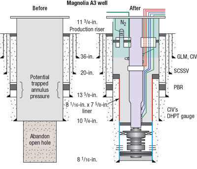 |
Fig. 5. To avoid a tubing leak later in the A3 ST2 well’s life, a tapered 8.062 x 7.625-in. liner (red) was extended to cover the 10.75-in. liner top, right.
|
|
The major downside to the chosen option is that future sidetracks from the A3 ST2 well will likely be kicked-off from a whipstock in the 7.625 x 10.75-in. casing or a whipstock set above the 7.625-in. liner top. Sidetrack points below the 7.625-in. liner top will require milling through two casing strings. Although this will require more time and expense, it is a technically acceptable plan for the well, providing the two strings are cemented.
CONCLUSIONS
Collapse of an uncemented liner hanger PBR is a potential problem on wells during production. The potential collapse issue at Magnolia field has been successfully handled through heavy brine and liner lap across the PBR.
This experience leads to the following recommendations. Trapped annulus analysis should be performed on liner hanger components prior to their installation in production wells. Personnel should ensure that cement is placed across the liner hanger through the primary cement job or liner top squeeze, if necessary.
FEA gives a better estimate of collapse pressures than API formulas for “short” members, so detailed FEA should be used to determine whether potential cases are acceptable.
In addition, completion designers should investigate the use of an expandable patch to maintain drift diameter and solve potential collapse issues. Liner tie-backs stems should land as close to the bottom of the PBR as possible to minimize or eliminate PBR collapse issues. The amount of allowable buckling in tieback string should be determine to ensure that the subsea casing hanger will land in the wellhead, if the tie-back stem bottoms out on the PBR. Finally, engineers should verify the ability of at-risk components to withstand collapse load by conducting an underbalance test prior to completion to avoid collapse issues with a live well. 
ACKNOWLEDGMENTS
The authors thank ConocoPhillips and Devon Energy Corp. for permission to publish this paper and Olli Coker for analyzing this problem. We also thank Stress Engineering Services Inc. and Baker Oil Tools for some of the figures.
LITERATURE CITED
1 Eaton. L. F., S.C. Actis, R.N. Williamson, C.G., Vernier, J., Long, “Deepwater batchset operations through the Magnolia shallow water flow sand,” SPE/ IADC 92289, presented at the 2005 SPE/ IADC Drilling Conference, Amsterdam, The Netherlands, February 23 – 25, 2005.
2 Reinhardt, W. R., R. N., Williamson, L. F., Eaton. S. C., Actis, “Magnolia Deepwater Development - Striving for best in class drilling performance,” SPE/ IADC 42439 presented at the 2005 SPE/ IADC Drilling Conference, Amsterdam, The Netherlands, February 23 – 25, 2005.
3 Vargo Jr., R. F., M., Payne. R., Paul, J., LeBlanc, J, Griffith, “Practical and successful prevention of annular pressure buildup on the Marlin project,” SPE 77473 presented at the SPE Annual Technical Conference, San Antonio, Texas, September 29 – October 2. 2002.
4 Rodriguez, W. J., W. W., Fleckenstein, A. W. Eustes, “Simulation of collapse loads on cemented casing using finite element analysis,” SPE 84566, presented at the SPE Annual Technical Conference, Denver, Colorado, October 5 – 8, 2003.
5 Inciarte, L., L., Nicio. “Analysis of collapse failures on production tubing during steam injection process assisted by computer simulations,” SPE 81155 presented at the SPE Latin America and Caribbean Petroleum Engineering Conference, Port-of-Spain, Trinidad and Tobago, April, 27 – 30, 2003.
|
THE AUTHORS
|
| |
Luke Eaton is the Deepwater Gulf of Mexico engineering coordinator for ConocoPhillips. Eaton has worked over five years for ConocoPhillips, on drilling and completion programs for the Magnolia TLP development. Prior to ConocoPhillips he worked 18 years for Shell in Houston, New Orleans, and Anchorage. He earned a BS in Mechanical Engineering from Texas A&M University.
|
|
| |
Randall Reinhardt is senior staff drilling/ completion engineer for ConocoPhillips working on the Magnolia TLP Development project. Prior to joining ConocoPhillips, he worked two years for Dowell Schlumberger and four years for Sedco Forex. Reinhardt earned a BS in Petroleum Engineering from Texas A&M University in 1984.
|
|
| |
Scott Bennett is a completions engineer for Devon Energy. He has worked five years for Devon, with the last two years on the completion program for the Magnolia TLP development. Bennett earned a BS in Petroleum Engineering from Louisiana State University.
|
|
|

