Environmental Technology
Useful criteria for selecting a watercut monitor
Operators need to know what factors affect monitor performance before choosing the right watercut monitor for the job.
Kevin Lavelle, AMETEK Drexelbrook, Horsham, Pennsylvania
Measuring the percentage of water in oil (watercut) is necessary in oil production. Several technologies are used to measure watercut across a full range of applications. Among the criteria for selecting which technology to use includes accuracy, sensing range, process characteristics, mechanical configuration, maintenance requirements and price. Each technology addresses the identified criteria through various design approaches. However, to achieve the greatest value and performance, device users should be conscious of their application parameters before selecting the right technology. This article provides a basis for comparing the capabilities, advantages and disadvantages of watercut technologies.
This paper is limited to the discussion of in-line, dual-phase measurement devices that are used for process control and custody transfer. It does not attempt to discuss technologies that measure in the PPM ranges (fluorescence, aluminum-oxide, etc.), or the various sampling techniques that are used in field operations and the laboratory.
THE TECHNOLOGIES
Four basic in-line analytical instrument technologies are used to measure the percentage of water in oil: capacitance, microwave, spectroscopy and density. All of the four technologies rely on electrical and/or mechanical fluid characteristics in determining the measurement. Because of the differences in each of these sensing methods, device users should have at least a basic understanding of the strengths and weaknesses of each technology to select the right instrument for their application.
Capacitance. The oil industry has successfully used capacitance technology to measure watercut for over 40 years. That success is due to the significant difference in dielectric constants between oil (kH2.3) and water (kH80). Figure 1 shows the sensing element (of radius a) and the pipe-wall (of radius b) that form the two plates of the cylindrical capacitor. Capacitance, C, is measured as:
 |
Fig. 1. Basic parameters of a standard cylindrical capacitor.
|
|
The system’s electronics transmit a radio frequency voltage to the sensing element that measures changes in capacitance. As the watercut in the fluid stream increases, the net dielectric of the fluid increases, causing the capacitance to increase. The instrument’s onboard electronics then computes the relationship between capacitance change and watercut.
Key advantages of capacitive instruments are stable (and proven) measurement technology, simple design, insensitivity to water conductivity and an ability to handle a majority of oil patch applications. It is a common misconception that capacitive instruments are limited to the linear segment of the capacitance vs. watercut response curve. The capacitance instruments are able to extend into the nonlinear range through the use of “strapping” tables. Typical capacitance instruments are able to put in multiple calibration points that can be fitted to the nonlinear region of the curve. Figure 2 shows data points from a typical strapping table that tracks the changing watercut through a nonlinear capacitance response.
 |
Fig. 2. Correlation of capacitance to water content.
|
|
In addition, capacitive instruments are typically among the lowest cost options relative to other measurement technologies.
Disadvantages of capacitive instruments are their difficulty in handling changing process factors (see below) and their limitations in measurement range. Capacitive instruments are limited to watercut ranges that are below the inversion point of oil and water. As the fluid becomes water continuous, conductivity dramatically increases, creating an electrical short to ground. The short to ground drives the capacitance to infinity and obscures the dielectric information. This phenomenon typically occurs at about 50% watercut in light oil and at 80% in heavy oil.
Microwave. The technology relies on the different electrical properties of the oil/ water mixture to determine the watercut measurement. Measurement of the water cut is performed by measuring the complex permittivity properties of the flow stream using a multiple high-frequency method. An oscillator transmits a microwave signal at a precise frequency, typically above 1 MH3, via an insertion probe that travels through the fluid. As the percentage of water in oil rises, the attenuation of the microwave signal will change in direct proportion to the water content. That change in signal is measured electronically, and the relationship between microwave signal change and watercut is determined, Fig. 3. This method will compensate for the effects of modestly changing hydrocarbon composition, as well as water salinity.
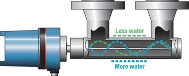 |
Fig. 3. Microwave technology: Attenuation and frequency shift of the signal determines the watercut.
|
|
Advantages from advancements in microwave technology have benefited this method. Two of these are accuracy in the lower cut ranges and the capability to measure the full range of watercut (0 – 100%). The microwave-based systems are also more robust in handling process factors that can negatively affect other watercut measurement technologies.
Disadvantages of microwave technology include its high initial cost relative to other technologies and its sensitivity to salinity changes in the higher cut ranges. Further explanation of the effects of salinity on watercut is outlined below.
Spectroscopy. The basic principle behind spectroscopic measurement of watercut is the response of an oil/ water mixture to light. A spectroscopic device emits an infrared beam that ignores the water phase of the mixture, reacting solely to the oil phase. Signal receptors on the device measure the absorption, reflection and scatter of the infrared beam and make a direct correlation to watercut, Fig. 4.
 |
Fig. 4. Signal receptors for spectroscopic watercut device.
|
|
There are several advantages for spectroscopic watercut measurement. First is its ability to measure across the full range of watercut. The percentage error actually decreases as the watercut increases. The technology’s accuracy at the high end of the watercut range separates it from other competitive technologies. Another advantage is that the technology is unaffected by changes in density, salinity or entrained gas.
A major disadvantage of spectroscopy-based watercut products is that they lack the necessary accuracy at the lower cut ranges, which limits the number of suitable applications. For example, spectroscopy-based measurements are not a good choice for Lease and Automatic Custody Transfer (L.A.C.T.) sites that have cut ranges of 0 – 3% water in oil per API Specification 11N. Users of infrared devices must also recognize that these instruments have a narrow defined sampling region. The sampling region emits an infrared beam that is reflected, absorbed and scattered over a potentially small representative region of a very large sample. Thus, it is possible that this narrow beam might not provide a true measurement of the entire process flow.
Density. Density is the only measurement method that uses a mechanical solution to measure watercut, and it is usually done with a coriolis flowmeter. To measure density, fluid enters two flow tubes that are mechanically driven to vibrate at a certain frequency. As the fluid flows, its inertia causes a slightly different bend in the inlet and outlet of the tubes, which causes the driven frequency to change, Fig. 5. If there are any density changes, the inertial mass changes and, thus, the frequency at which the tubes oscillate changes. The watercut can be determined from those changes. By knowing the initial densities of the water and oil, the output of the coriolis meter reflects the densities of the combined fluids. The coriolis meter electronically takes that output density and solves for the assumed single variable – watercut.
 |
Fig. 5. Typical arrangement for a coriolis flowmeter. Driven frequency changes with flowrate and density.
|
|
The advantages of this technology are its cost-effectiveness and its ability to provide additional information, such as flowrate, temperature and density that can be used as input for process optimization.
A drawback to using a density measurement for watercut occurs when process variables start to change. Flowrate must be known, since it can affect the oscillation rate of the device. Introduction of gas and salinity into the process immediately effects the watercut measurement and can significantly impact the accuracy of the device. The use of density to measure watercut is typically confined to light oils due to the limited difference in density between water and heavy oil. Density-based watercut measurements encounter additional uncertainties when applied to waterflood enhanced oil recovery processes. Since the density of the oil and water must be known beforehand to measure watercut, the reservoir mixing of native and injected water creates uncertainty in the density of the produced water and, thus, uncertainty in watercut.
PROCESS CHARACTERISTICS
As outlined above, each measurement technology has its own strengths and weaknesses, depending upon process conditions. It is very important for users to identify process characteristics before deciding on a particular technology. Below are key factors that have the greatest effect on deciding which technology to use in making the watercut measurement.
Density. Any variation in density (degree API) significantly affects the capacitive, microwave and coriolis/ density measurement. As explained above, capacitive and microwave measurements are based on the electrical properties of the mixture. Therefore, any change to the electrical property – in this case the dielectric of the oil being shifted by density – severely impacts the measurement technique.
The introduction of entrained gas also affects the fluid’s electrical properties of the fluid. Entrained gas will cause additional shifts in the net dielectric of a fluid that now has a mixture of entrained gas (k=1), oil (k=2) and water (k=80). Entrained gas causes a downward shift of the watercut measurements. The coriolis/ density measurement is also affected by changes in API gravity of the fluid. Any change in API density requires recalibration of the initial values entered into the sensor.
The oil industry has recognized the effects of varying densities and has made significant efforts to address these concerns in measuring watercut. Coriolis meters, to measure density only, are used in conjunction with microwave and capacitance probes to arrive at a corrected output. Separation techniques can also be used to reduce the amount of entrained gas within the process that can have a positive impact on the watercut measurement. In addition, several manufacturers have published specifications regarding sensitivity to density changes. Users should understand how density varies in their processes and choose the right technology to handle those variations.
Salinity. Obviously, any instrument that depends on conductivity for watercut will be sensitive to changes in conductivity of the water. An increase in salinity will cause such an increase in conductivity. Any device that emits a transmission signal is dependent on the properties of the fluid to carry the signal as well. Changes in salinity will cause changes in the electrical signal propagation through the fluid.
Salinity effects have the greatest impact at the higher cut ranges, where the process becomes water continuous. In the oil-continuous (non-conductive) phase, the fluid is insulating and the floating salts have limited effect on the net conductivity. Once the fluid enters the water-continuous phase, it becomes highly conductive, and the salt content amplifies the electrical path to ground.
The four principal technologies for measuring watercut have varied responses to conductivity changes. Density measurement is affected by the introduction of additional solids in the measurement. Errors are associated with salinity in microwave-based devices only in the water-continuous phase, where the fluid is conductive. Microwave devices are calibrated for a specific conductivity, and change in this property will result in a calibration error.
Manufacturers of capacitive technologies design their coaxial-sensing element to reach full signal saturation and ignore changes in conductivity. The advantage of a saturated probe is that the signal detects changes in watercut only as long as the probe remains saturated. The disadvantage is that, if the conductivity change is significant enough for the probe to lose saturation, then the electronics will not display the correct value. The majority of oilpatch applications do not see enough salinity variation between well formations to lose probe saturation. However, with applications that may see oil from multiple sources (such as the receiving point at a refinery), there is increased probability of losing probe saturation.
Temperature. Density and, therefore, the dielectric constant of the fluid, are affected by changes in the temperature of the process. As temperature increases, the density decreases (reducing the dielectric), causing an error in the watercut measurement. Temperature variations do not cause as dramatic a response as do changes in salinity or API gravity. However, the ability to correct for temperature fluctuations increases the accuracy and repeatability of the watercut measurement. That ability is particularly important in custody transfer applications, where a 0.5% change in watercut can have significant implications. Most manufacturers do some form of temperature compensation to correct for this effect.
Homogeneous sample. The sensing element must be exposed to a representative fluid sample to make an accurate measurement. A common problem seen in process conditions is independent slugs of oil, gas or water reaching the sensing element. These slugs are usually caused by some form of separation that occurs before it passes through the sensing area of the instrument. The separation is often more critical at watercuts above 50%, where the fluid property differences (such as density and viscosity) will cause a portion of the oil/ water emulsion to separate into a free-water phase. As this occurs, the measurement instrument is subjected to multiple parallel, and very different, fluids.
Figure 6 reveals the dynamic emulsion states that occur within flowing process conditions. Watercut devices are based on the assumption of a single-phase measurement and now must attempt to understand a multiphase process comprising a free water and oil emulsion. Elimination of free water via additional process separators and the addition of inline mixers are some of the more common solutions to provide a true representative sample to the sensing element.
 |
Fig. 6. Watercut devices assume a single phase measurement. A multiphase process comprising a free water and oil emulsion should be avoided.
|
|
INDIVIDUAL PRODUCT CAPABILITIES
If choosing the right cut monitor technology weren’t difficult enough, there are more than 15 manufacturers of watercut instruments. All use the four basic technologies listed above. With that in mind, identifying additional instrument characteristics should be of value to users.
Accuracy range. Some technologies are limited to certain cut ranges. Spectroscopy-based instruments are able to measure the whole range and increase in accuracy at the higher cut ranges. That technology, however, is not useful for accurate, low-range cut measurements. On the other side of the spectrum, capacitance devices offer excellent accuracy and repeatability at the low-cut ranges, but are limited by the water/ oil inversion point. Microwave measurements offer accuracy throughout the entire range, and their premium price reflects that capability.
With the technology limitations on accuracy at different watercut levels, it is clear why certain technologies are better suited for certain applications. The spectroscopy measurements are ideal for monitoring well testing at high watercuts and for discharged sump water. Conversely, applications at lower cut ranges are better suited for capacitance and microwave devices. Examples of applications that require lower cut range devices include custody transfer and pipeline monitoring. The user must decide the technology that best fits the measurement requirement, as well as the instrument that best implements that technology.
Communication output. While all instruments provide the standard 4-20 mA output, some manufacturers have equipped their devices with additional capabilities. Utilizing digital protocols, embedded relays, multiple 4-20 mA signals and wireless communications are just some of the output options being provided.
By incorporating these additional communication techniques, the instrument’s electronics can transmit density, temperature and net oil calculations. The additional outputs also reduce the need for extra sensors, thereby minimizing capital expenditures and maintenance expenses.
Embedded relays are of particular importance in applications where the cut monitors are used to divert oil with high-water content. The use of digital protocols is gaining in popularity because it allows users to remotely query the device for diagnostics or to make needed calibration changes.
Sensor design. Various mounting options are available. Among the most common is the dual-flanged spool piece, Fig. 7. A different approach taken by some producers are threaded NPT and slipstream designs that permits a more customizable solution than a spool piece.
 |
Fig. 7. Typical arrangement for spool-piece type cut monitors.
|
|
Maintenance should be considered in choosing the correct sensor design. Users should ask:
- Is the probe susceptible to paraffin buildup? How easy is the device to clean and/or replace?
- Does the sensing device measure a representative fluid sample?
- Are there any seals, coatings or fittings that require regular replacement?
- How well do the external electronics stand up to harsh ambient conditions?
These questions all need to be addressed in choosing a particular design.
An insertion probe that can be installed directly in the process stream offers additional advantages when evaluating different sensor designs. For example, the insertion probe used by some capacitance devices allows the sensor to acquire samples over the entire length of the probe, providing a larger representative mixture sample. The longer probe creates a capacitive-averaging effect along the probe that allows the electronics to calculate a more accurate measurement.
Net oil calculation. Net oil calculations are gaining in popularity with the integration of computing devices, PLCs, flow meters and watercut instrumentation. A packaged net oil calculation offers end users a dedicated system that has been installed, calibrated and optimized by a single supplier. It eliminates the need for users to piece together individual components to compute net oil.
Startup and commissioning. A certain depth of knowledge and experience is required during installation of a new cut monitor to get the best performance from a unit. The level of service and local support that an OEM provides is of great importance in choosing a device. Due to the increasing complexity of the various technologies, the use of factory representatives for installation and startup services has become a popular option with the purchase of these devices.
Price varies significantly among cut monitor products. Users could spend from $2,500 to $30,000 for a device. Price is dependent on the range and capabilities of a device. Such extras as digital communications and net oil calculations may add significantly to the base price.
CONCLUSION
To get the best performance and value from a cut monitor system, it is necessary for the user to have comprehensive data on the process parameters and product characteristics that influence performance. New cut monitor systems should be evaluated on the basis of accuracy, sensing range, process characteristics, mechanical configuration, maintenance requirements and price before making a purchasing decision. Armed with sufficient knowledge of the process and technology, such as the advantages and disadvantages outlined in this article, users will be better able to decide which instrument best implements the technology. 
REFERENCES
Yang, Y. S. and B. N. Scott, B. B. Cregger, “The design, development and field testing of a water-cut meter based on a microwave technique,” Society of Petroleum Engineers, Paper SPE 20697-MS Annual Technical Conference and Exhibition, September 23 – 26, New Orleans, Louisiana, 1990.
Noelck, B., “Watercut Best Practices 101,” Spartan Controls, Alberta Canada. Also presented at Canadian School of Hydrocarbon Measurement (CSHM), Calgary, Alberta, Canada, March 22 – 23, 2005.
“Specification for Lease Automatic Custody Transfer (LACT) equipment,” API Specification 11N, Fourth Edition, November 1, 1994, eProduction Solutions, a Weatherford Co., www.ep-solutions.com, June 1, 2005.
|
THE AUTHOR
|
 |
Kevin Lavelle, is product manager for Analytical Technologies. Before joining AMETEK, he was employed by the United States Navy as technical expert for Sensors and Instrumentation. Mr. Lavelle earned a BS degree in mechanical engineering and an MBA from Drexel University. Email: Kevin.Lavelle@Ametek.com
|
|
|


