What's new in artificial lift
Part 1 - Twenty new systems for pumping, plunger lift and gas lift.
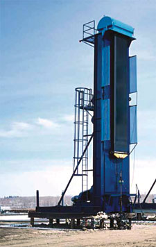
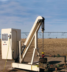
Artificial LiftWhat’s new in artificial liftPart 1 – Twenty new systems are described for sucker rod and progressing-cavity pumping, plunger lift and gas lift.James F. Lea, Mewbourne School of Petroleum and Geological Engineering, Oklahoma University; Herald W. Winkler, Texas Tech University; and Robert E. Snyder, Consultant Described here are 20 recent developments from 10 companies in four categories of artificial lift technology: sucker rod pumping (seven items); progressing-cavity pumping (PCP) (five); plunger lift (five) and gas lift (3) Part 2, coming in May, will present electrical submersible pumping (ESP), and other, miscellaneous artificial lift innovations. Sucker rod pumping, now evolved from classic beam pumps to include tower type units, is the most widely used artificial lift, using the vertical rod motions, now also with cable, to operate a downhole reciprocating pump. PCP systems are based on a surface drive rotating a rod string, which drives a downhole pump rotor operating within an elastomeric stator. In plunger lift, a freely moving plunger falls through fluids in the tubing and is lifted back to surface with its slug of mostly liquids by higher-pressure, formation gas (or injected gas) from the tubing-casing annulus. Gas lift in valves injecting annulus gas under liquid columns or plungers in the tubing to drive to surface. SUCKER ROD PUMPING The seven new systems are recently applied by five companies, or are in the final test phase. They include: a larger tower type, longer stroke pumping unit; a hang-off tool to temporarily unseat and raise rods and pump; a gas-engine-driven power system to replace electric motors; two low-profile/ low-cost rod pump units; a full-time, computerized downhole pump card; and a new tower type unit employing reciprocating downhole cable instead of sucker rods. Larger Rotaflex* system available. The Rotaflex* is Weatherford’s long-stroke pumping system for sucker rod pumps, Fig. 1. This system uses proven technology and design innovations to provide greater efficiency and cost-effectiveness for deep, troublesome and high-volume wells. With the unit, rod pumps can be used for applications where electric submersible or hydraulic subsurface pumps were once required. The larger unit has up to a 366-in. (30.5-ft) pump stroke.
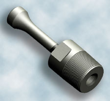
The unit has virtually no minimum speed. Slower speeds and longer strokes result in more complete pump fillage and lower dynamic loading. Key benefits include efficient handling of high volumes, high loads and deviated wells; and reduced rod/ tubing wear with fewer cycles and reversals. The mechanical reversing mechanism is field-proven in over 800 units. The system’s long-life, heavy-duty-load belt links power train and rods and acts as a shock absorber, reducing entire system stress. The short-radius torque arm reduces torque demand, allowing use of a smaller prime mover and gear reducer. To service a unit, after bridle and carrier bar are disconnected, the unit rolls away. When workover is completed, the unit is rolled back into place, and the carrier bar is reconnected. Hang off tool. Harbison-Fischer, Ft. Worth, Texas, has finished testing and is offering a unique sucker rod hang off tool, Fig. 2. When a rod-produced well needs to have the rod pump unseated and hung in the tubing, the pump is lifted and the Hang Off Tool (HOT) is screwed onto the top rod at the surface, then lowered and screwed into the flow tee above the tubing string. The steel tool has a built-in sub for lifting the rod string and lowering it onto the flow tee. Some operators attach a hammer union, so the rod string does not need to be rotated when lowered.
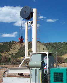
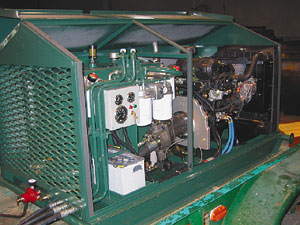
This installation seals the wellbore and hangs off the rod string, providing safer installation than homemade hang-off tools. HOT conforms to NACE specifications for unhardened steel material service. It is available in several commonly used sizes. Gas engine-driven power unit. DynaPump, Inc., Northridge, California, has announced the newest addition to its line of pumping systems, the Natural Gas DynaPump power unit, Fig. 3. It pumps liquids efficiently. Many oil and gas wells can be operated cost-effectively by using natural gas instead of electric power, freeing electricity for other needs. The unit provides one possible solution for producing maximum flow at the lowest lifting cost. Gas consumption is reportedly about 20% of conventional beam-pump power consumption, and the unit maintains all built-in controls, communications and feedback that the electrical unit may have.
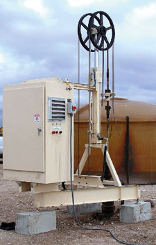
The power unit control center can convert input power to hydraulic power, and control pump stroke as needed. The system allows for independent speed control, in both up and down directions, and for independent adjustments of top and bottom strokes. It also can adjust speed automatically to provide pump-off control. Major operators are using the new power unit in more than 50 wells, resulting in increased cash flow with many environmental benefits. Low-cost rod pumping system. DynaPump has recently launched its new DynaSave a low-cost rod pumping system, stated to require low maintenance, Fig. 4. This very compact unit – one can be moved on a pickup truck – has flowrates up to 640 of barrels fluid per day (bfpd) from less than 750 ft, and can pump 40 bfpd from 5,000 ft; maximum rod load capacity is 7,000 lb.
Its 72-in. adjustable stroke, allows for slow speeds at higher flows than conventional units. It is recommended for use with 5/8-in. rods. Following past DynaPump operation techniques, this unit has a variable speed up and down, and an automatic pump-off controller. The cylinder seals are field serviceable. It is powered by a 480V, three-phase motor; or 220V/480V single phase as an option. The unit complies with API 500 code. Low-profile pump unit. Another contribution from DynaPump is the DynaLow, a low profile unit with the same capacity and specifications as the DynaSave unit. It has a fixed height of less than 10 ft and a maximum stroke of 40 in., Fig. 5. This unit has been designed to work under farmland irrigation systems. Total weight is less than 1,400 lb. It is stated to have design features making it a safely operated unit.
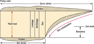
Pump intake pressure from downhole card. Pump-off controllers have evolved to become full-time dynamometers. Today, wellsite computers accurately measure load and position, along with pressures, temperatures, production rates, etc. This sophistication requires accurate measurement of surface load as a function of position. The SAM Well Manager from Lufkin Automation, Houston, not only calculates an accurate downhole pump card for every stroke of the pumping unit, but it also calculates pump intake pressure. This is important in managing flow regimes and pressure support initiatives. Getting this information daily, as opposed to whenever manual fluid levels can be recorded and analyzed, allows continual improvement. Pump intake pressure can be calculated using the downhole pump card, Fig. 6. Input data from the card includes fluid load, gross stroke, net stroke and tubing movement, if applicable. Fluid load, the most important item, is the difference between upper and lower load lines, selected and drawn on the card. This load should not include friction and fluid inertia effects. Ideally, the lower load line should fall below zero load by the same amount as buoyancy; accuracy of the buoyancy calculation depends on good load measurements, rod design information and a known tubing fluid gradient. With all input data, a pump intake pressure can be computed. During this process, other items of interest are indicated, as in the example card.
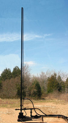
Replacing sucker rods with cable. A new oil well pumping system using cable instead of rods is being developed and tested by Vann Pumping Systems, Inc., Tyler, Texas. This system employs steel cable instead of sucker rods, and a surface Tower Lift unit that replaces the pump jack, Fig. 7. The pumping lift system connected to the cable is computer controlled. New patented tools have been developed and tested to reduce gas locking and pump off. The patented Vent Tools are run at the bottom of the pump barrel to allow fluid dumping from the tubing when desired. A couple of functions of these newly developed tools are for ease of unseating from hold-down and chemical spotting.
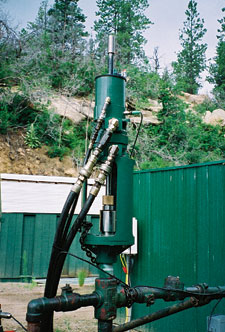
Testing results have shown many advantages, i.e., fewer and longer strokes per minute, producing more oil and eliminating clocks by producing 24 hr/day. This is performed by the computerized system keeping an optimum fluid level in the annulus. This control is possible using lifting pressure instead of tension to measure in realtime and to instruct the computer as to the strokes per minute. An economic value is recognized when maintenance is required. A special cable unit is brought out to reel up and repair the downhole pumping assembly and return it to bottom; no workover unit is needed. This pumping method is in an advanced testing phase and will be available in the near future. PROGRESSING CAVITY PUMPING Five PCP advances from two companies include: a three-component gas well deliquifying pump; a hydraulic power skid with power source, hydraulic motor and controller; a liquid level monitor that alters PCP speed; a new loop to simulate downhole pumping system conditions; and a new-version PCP software program. PCP drive system dewaters gas wells. Hydraulic Energy Products, Inc., (Applied Energy Products, AEP, spinoff), Denver, Colorado, has developed a three-component drive system to automatically de-water gas wells, especially coalbed methane wells. The complete system is self-monitoring and regulating, with signal capability to alert the operator if drive speed goes above or below pre-determined set points. Variable speed with manual control is achieved by applying the Top Head Drive and the Hydraulic Power Skid only. The direct Top Head Drive hydraulic, motor-driven unit from HEP is offered in four torque ranges and utilizes the conventional friction lock block to connect to the 1-1/4-in.-diameter polished rod, Fig. 8. The largest drive motor is capable of supporting string and water column weights to 5,000-ft depth, while delivering 2,000 bwpd; or 4,000 bwpd from 2,500 ft. The maintenance-free drive operates through a rotary union, replacing the conventional stuffing box.
Complete control of “back-spin” is achieved in conjunction with the HEP hydraulic power skid, and in the two larger sizes, a fail-safe brake provides release or dissipation of stored energy. The drive can be mounted on a threaded adaptor, to the flow tee, or secured on the standard API 8-bolt flange. The drive is Hydraulic Power Skid, presently offered in two sizes: 12 in.3 and 26 in.3/rev. At present, there are 10 drive heads running, with initial units exceeding two years without service or maintenance. The HEP Fig. 9, is offered with natural gas-powered 2.5- or 4.0-l engines or 460V electric motors up to 100 HP. The HEP design incorporates complete secondary containment of all liquids and a full enclosure to prevent water buildup. The variable volume hydraulic pump is electro-proportionally controlled, with a feedback loop to assure accuracy and volumetric/ operating pressure efficiency. The onboard computer optimizes fuel mix and governs operating speed. It also monitors engine oil pressure, radiator temperature, hydraulic reservoir liquid level and temperature. The skid can reverse rotation of the Top Head Drive, with limited torque and speed, to dissipate stored energy, flush the PCP, or rapidly equalize fluid levels. The constant-speed electric motor drive system provides variable Top Head Drive speeds hydraulically and eliminates the need for a Variable Frequency Drive (VFD).
Liquid level monitor and controller. The proprietary controller from Applied Energy Products monitors, calibrates and alters drive speed of the downhole PCP – maintaining the desired liquid level, with calculations based on physical data and formation flowrate, for the specific well. Recalculation frequency can be altered to meet fluctuating well conditions. The Liquid Level Controller (LLC) has two separate computers. The first gathers information or observes formation water flow increase or decrease into the well casing, while the second analyzes and generates the appropriate signal, causing the hydraulic pump to increase or decrease flow to the drive motor, changing the speed of the downhole PCP. The LLC maintains the liquid level between lowest perforation, or any user defined level, and the PCP inlet – thereby maximizing gas production. The controller offers a manual mode for setting a desired speed, and an automatic mode to remove guesswork. A signal is generated that may be transmitted by a SCADA system – if the operating range (high or low) is exceeded – with a detailed recording of system performance. The LLC, being the last component introduced, has been installed on operating wells and the concept proven; however, it has not yet been released to the general market. Experimental simulation loop. C-FER Technologies of Edmonton, Canada, recently commissioned an experimental loop to simulate downhole conditions for pumping systems operating in steam-assisted gravity drainage (SAGD) applications, Fig. 10. Pumping equipment of up to 80 ft (24.4 m) in length can be tested at maximum discharge pressures, intake temperatures and flowrates of 1,100 psig (7,580 kPag), 200°C (400°F) and 5,050 bpd (800 m3/d), respectively.
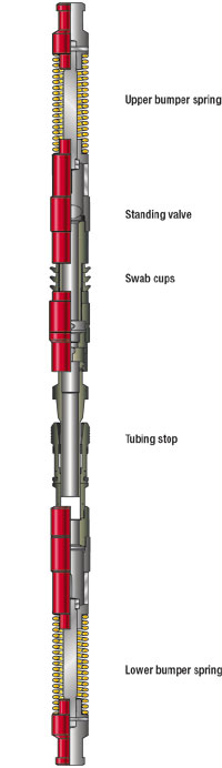
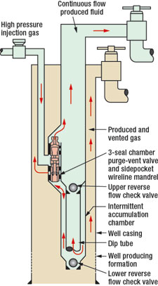
The flow loop has multiphase capabilities (oil, water, air) and is fully instrumented to allow real-time measurements of all key variables (pressures, temperatures, flowrates, pump speed, torque, etc.). This makes the loop an ideal tool to ascertain performance of new artificial lift systems under controlled conditions before actual field tests are undertaken. Testing of four pumping systems has already been completed under a JIP. Services offered by C-FER include design, execution and data analysis of pump testing programs, for both operating companies and equipment manufacturers. PCP software program. A new version of PC-Pump (2.67), a well-known proprietary software program for interactive design and evaluation of PCPs, has been recently released by C-FER Technologies. Upgrades incorporated in this latest version include: updated equipment databases from vendors (pumps, rods, drive heads, etc.); improved wellbore temperature gradient and inflow performance calculations; and an improved batch-run comparison mode to facilitate assessments over a range of operating conditions. PLUNGER LIFT Five new plunger lift-related technologies from two companies include full-featured PC-based control/ data acquisition, a self-adjusting algorithm-driven controller, increased by-pass plungers, multiple plungers in the same well, and the latest addition to a series of PL controllers. Plunger control/ data acquisition. The Auto-Cycle* plus ACP SCADA Client* is a full-featured PC-based control/ data acquisition system of Ferguson Beauregard (FB), Tyler, Texas, with an intuitive Microsoft Windows graphical user interface. Operators can manage wellhead production anytime via a PC connection to the company’s LAN/ WAN. The multi-user system enables pumpers to group wells and liquid tanks by route. The “Go-Mobile” feature downloads route data to the mobile computer. As the pumper travels, additional information is recorded manually for non-automated processes using the Walk-up SCADA feature. In the office, adjustments and manual data are synchronized and stored in a SQL data base. Analysis features include trending and schematic trace. The latter enables polling the well repeatedly for real-time visualization of its performance and also stores data. All production data is available for query and reporting via third-party applications, including Crystal Reports. The ACP SCADA Client is integrated with the RTU5000* controller. It is pre-programmed with FB’s patented Auto-Cycle plunger-lift control algorithm. Auto-Cycle makes adjustments to after-flow and shut-in time based on plunger travel velocity. Various control strategies include plunger-lift control for up to four-valve operation, gas injection and Plunger Enhanced Chamber Lift (PECL). Product features include low power for remote installations; CSA certification for Class 1, Division 2; programmable flash for local/ remote upgrades; and dual protocol support for telemetry (native FB/ Net2 and industry-standard Modbus). Telemetry options include landline modem, cellular, radio and satellite. Valve production method. The most attractive feature of this Ferguson Beauregard controller, in addition to increased production, is the simplicity of the method and that it is used in conjunction with plunger lift for the same costs. This controller utilizes an algorithm that allows production from both tubing and casing, as opposed to the tubing only. The algorithm has the ability to self-adjust control parameters dependent on present well conditions and control production from the tubing, the casing, and both tubing and casing. The larger cross-sectional diameter of the casing provides a larger flow area for increased production. In the 3-Valve Production Method, production is from the tubing, both the tubing and casing, and casing only during a plunger cycle. Wells in the Texas Panhandle, Kansas and Oklahoma regions have shown about two-fold increases in production. Bypass plungers. Plungers are finding their way in newer applications and more diversified conditions as a result of continued improvements in design and applications. The Bypass Plungers by FB are a direct outcome of this. They can be broken into two categories, “continuous flow” and “short shut-in flow” plungers. Continuous flow plungers are used in wells where it is imperative that the plunger returns to bottom quickly. This is made possible by having a larger bypass area. These wells may be flowing around their critical flowrate, and do not need to be shut-in to build up pressure; and they may be producing moderate to considerable liquids. The bypass is open when the plunger is falling, and closes upon hitting the bumper spring. Upon reaching surface, the bypass mechanism opens a passage for fluid to flow through, and the plunger falls back when flowrate drops. Short shut-in flow plungers are used in wells flowing at rates lower than critical and for wells that have to be shut-in for a short time for pressure buildup. These plungers fall against lower flowrates, but essentially the well has to be shut-in to build up pressure. Since the time required to build up pressure is small and the well may be deep (say 12,000 ft), it is important that the plunger falls and reaches bottom within that short shut-in. This would not be possible with good-sealing, conventional plungers, which require additional shut-in to reach bottom, while short shut-in plungers would reach bottom within that time. Super Flow by FB is such a plunger. The shut-in time has been observed to be less than 15 minutes for depths up to 12,000 ft in many installations. Success of these bypass plungers has increased acceptability of plunger-assisted artificial lift for deep wells. Progressing* plunger system*. Weatherford’s Progressing* plunger system* (PPS) uses multiple plungers in the same well to optimize use of lift gas. The PPS makes use of gas available between multiple stages to lift fluids; it also uses gas from below the lowest stage, which usually comes from the formation or from backside pressure. This optimization of lift gas effectively reduces gas liquid ratio (GLR) by as much as 1 – 3 Mcf/bbl, as it also reduces formation or casing pressure needed to achieve the lift. The PPS is installed for these staged plunger-lift applications; i.e., wells: 1) with low GLRs, usually borderline conventional candidates; 2) with inadequate lift gas to ensure optimal plunger arrivals with acceptable liquid production; 3) that must be shut in on plunger arrival because of fluid inflow during the cycle; 4) that have matured to minimal reservoir pressure and can no longer operate conventionally; 5) that have become uneconomical with compressor rental for gas lift; and 6) for which rod pumping is technically feasible but economically impractical. The PPS can be added to an existing plunger system if an intermediate landing assembly and a second plunger are added. Use of existing equipment reduces costs. The PPS is installed as follows: Remove existing plunger. Run wireline. Pull bottomhole bumper spring. Run a gauge ring to tag TD, and establish fill. Run original bumper spring, and drop lower plunger. Run and set Type A tubing stop, crossover and lower bumper spring assembly at setting depth (about 65% of TD), Fig. 11. Run upper bumper spring with standing valve, swab cup mandrel, and collet latch, and set assembly on tubing stop. Return wellhead plunger lubricator, load upper chamber, and drop upper plunger. Optimize well based on reduced travel time relative to reduced travel for upper plunger.
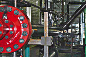
Plunger lift controller. Weatherford provides a complete line of electronic controllers for plunger lift and gas lift applications, to operate wells under various conditions. These contain real-time software with menu-driven formats to ensure smooth operation. Several models are available in the CEO* series. Each has a standard set of features and options to address specific applications. The latest model, the CEO IV Plunger Lift Controller is designed to meet remote requirements by using ultralow-power electronic technology. The design incorporates all the proven SCADA and RTU functions of other wellsite intelligence products, making it a complete and advanced plunger lift controller. This state-of-the-art system is designed with a programmed on-cycle initiation calculation accounting for casing, tubing and line pressures, as well as annulus volume, fluid load and tubing frictions. It can also be used to monitor tank levels, and it offers a broad range of control mechanisms, including time-based, using system pressure inputs; pressure-based; single-, dual- and triple-valve; flowrate and differential pressure. GAS LIFT Three new systems are introduced by two companies to improve the efficiency of using annulus gas to lift liquid columns in the tubing. Side pocket mandrel. Weatherford’s SBRO-DVX side-pocket gas-lift mandrel, Fig. 12, features unique dual-pocket communication channels that, when equipped with external backflow check assemblies, prevents well fluids from entering the casing annulus through gas lift valves or empty pockets. The mandrel can encompass multiple barriers to protect the annulus from corrosive fluids and pressure during operation and during valve change out. The mandrel will accept existing standard gas-lift valves and latches for maximum flexibility. It is available in 2-3/8- to 7-in. sizes, in a variety of materials for high-pressure and corrosive environments.
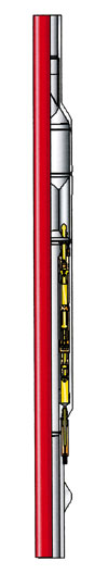
Applications include any well completion incorporating standard side-pocket gas-lift mandrels, including deepwater, high-pressure and/or highly corrosive well environments. Dual external valves prevent tubing fluids from entering the casing annulus. The dual-valve design also eliminates need for a positive check valve within the gas-lift valve, reducing required pressure drop at gas-lift valve depth. Thus, use of higher injection pressure lowers operating depth and improves system efficiency. Industry standard pocket configuration accepts 1.0- and 1.5-in.-OD gas-lift valves and latches from other manufacturers. No additional gas-lift equipment has to be purchased for upgrading to the new mandrels. Continuous gas pump. BST Lift Systems of Ventura, California, is seeking field test partners for two new innovative gas-lift products now in patent application. The first is a new production system which uses a downhole injection, gas-powered booster pump assembly to eliminate flow gradient back pressure on continuous-flow wells. The new system allows gas lift to compete with rod pump and ESP to produce a well from initial flow to final tertiary recovery. The new device can produce gaseous fluids, high-viscosity liquids, and those with entrained solids better than either rod pump or ESP. It can be installed on coil tubing, jointed pipe or a combination of both, with wireline retrievable capability, Fig. 13.
5,000-psi high pressure valve. The second innovative development from BST Lift Systems is a 0 to 5,000-psi+ operating pressure gas-lift valve with an improved bellows design which prevents overpressure and over-travel in existing 1-1/2- or 1 in.-OD standard configured valves. This unique bellows design provides for long-life operation utilizing standard high-pressure mandrels and proven wireline tools.
Perforated-zone gas lift system. The PerfLift perforated-zone gas lift system from Schlumberger is a cost-effective artificial lift system for low-rate, gas-lifted oil, liquid-loaded gas, and coal-bed methane wells. The system uses Camco gas lift technology in a simple completion architecture that enables gas lift across long, perforated intervals below a production packer. The system uses a series of Camco gas lift products both above and below a ported or dual-bore production packer. Conventional or side-pocket gas lift mandrels are installed in the upper tubing string. Internal gas lift mandrels and valves are sized and installed on the lower tubing string across the perforated zone. The lower tubing string is capped with a bull plug. The system can be used with a 4-1/2-in., 5-1/2-in or 7-in. ported or parallel flow packers. The tubing below the packer ranges in size from 1-1/4 in. to 3-1/2 in., depending on the packer and casing size. During system operation, gas is injected down the upper casing-tubing annulus and into the lower tubing string, through the packer, lifting the fluid column across the perforated zone. Liquid then travels to the surface through the upper production string.
|
||||||||||||||||||||||||||||||||||||||||||||||||||||||||||||||||||||
- What's new in production (February 2024)
- U.S. operators reduce activity as crude prices plunge (February 2024)
- U.S. producing gas wells increase despite low prices (February 2024)
- U.S. oil and natural gas production hits record highs (February 2024)
- Dallas Fed: E&P activity essentially unchanged; optimism wanes as uncertainty jumps (January 2024)
- Enhancing preparedness: The critical role of well control system surveys (December 2023)
- Applying ultra-deep LWD resistivity technology successfully in a SAGD operation (May 2019)
- Adoption of wireless intelligent completions advances (May 2019)
- Majors double down as takeaway crunch eases (April 2019)
- What’s new in well logging and formation evaluation (April 2019)
- Qualification of a 20,000-psi subsea BOP: A collaborative approach (February 2019)
- ConocoPhillips’ Greg Leveille sees rapid trajectory of technical advancement continuing (February 2019)

