Drilling Report
Real-time geosteering captures heavy oil sands value
Canadian Natural Resources Ltd. and Halliburton control horizontal wellbore placement with real-time geosteering.
Carmen Lee, Canadian Natural Resources Ltd., and Darcy Cuthill, Halliburton
The drilling team at Canadian Natural Resources Limited (CNRL) had a problem. They were attempting to place horizontal wells close to the base of the reservoir to capture maximum reserves in the Primrose field of northern Alberta, Canada. Unfortunately, the only way to find the shale bottom was by drilling into it, either on purpose or by accident. They then had to free the drill bit whenever it was stuck in the shale, and either settle for poor wellbore placement and lost reserves, or pull back and re-drill the section. There had to be a better way.
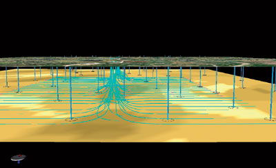 |
Fig. 1. The 3D shared earth model shows CNRL’s horizontal drilling program and the government-mandated stratigraphic test well program. Wells are drilled horizontally from a tightly spaced pad with eight wells in each direction.
|
|
Working in partnership, CNRL and Halliburton used real-time geosteering at latter’s Real Time Operations Centre (RTOC) in Calgary to place 55 horizontal wells precisely within one meter above the reservoir bottom. This was the first commercial-scale use of real-time geosteering in Western Canada.
In this project, geosteering reduced drilling time 40%, cut drilling costs 13%, eliminated sidetracks and decreased wellbore length in shale by 13.5%. It is expected to increase recoverable reserves by up to 10% once the wells come into production. This operation was done without a geologist at the wellsite.
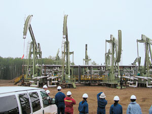 |
Fig. 2. CNRL and Halliburton have reduced drilling costs by 13% and reduced drilling time by up to 40% using a real-time approach.
|
|
PRIMROSE FIELD
CNRL has been drilling for heavy oil in the oil sands of Northern Alberta for many years. The Primrose field wells are drilled from pads, which have 16 horizontal wellbores each – eight horizontal wells going in one direction and eight in the opposite direction. Each wellbore reaches outward some 1,200 m into the lateral section.
These wells penetrate the Clearwater formation, which is interpreted as a compound-incised valley system filled with estuarine deposits. At a depth of 450 m, producing sands lie over shale. In some places, a thin layer of nonproducing or muddy sand is sandwiched between the sand and shale.
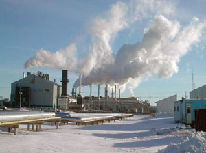 |
Fig. 3. CNRL’s Primrose field heavy oil operation uses the cyclic steam method, requiring wells to be placed deep into the reservoir.
|
|
Production from Primrose field is typical of many other heavy oil operations in Alberta: the thick oil is squeezed from the sands using cyclic steam generation. In this process, steam is injected into the reservoir for several months through horizontal wellbores placed low in the reservoir. This wellbore position creates a pressurized steam chamber that forces the heavy bitumen to flow downward into the wellbore. The bitumen is then produced and processed to a higher crude grade.
For this approach to succeed, the wells must be placed as close to the bottom of the producing sands as possible, because reserves below the wellbore cannot be produced. CNRL targets its horizontal wells to skim the base of the reservoir with a maximum one-meter clearance.
In the past, finding and staying within that sweet-spot was difficult. The situation was complicated by the need to stay not only above the shale, but also above a complex combination of non-reservoir sand, nonproducing muddy sand and shale. Attempts to use conventional gamma ray data to detect the reservoir’s bottom were unsuccessful. The drilling team resorted to a solution it called “tagging the shale,” which was a bit like finding the way through a room, blindfolded, by bumping into the walls. In this method, the drill bit cut into the shale either unintentionally or at predetermined points along the well path. These data points, combined with data from offsetting or nearby stratigraphic wells, allowed geologists to create a theoretical model of the reservoir to aid drilling efforts.
The tagging method was far from efficient, especially in the 15- to 20-m thick Clearwater reservoir, where placing a wellbore even five meters above the bottom could leave 25 – 30% of the reserves behind. With a drilling survey error of up to +/ – 7 m, a well could be way off the mark from optimal placement.
Driving the bit too deep was also a problem. If it entered the shale, the team lost time backing it out. Alternately, they could turn the bit out of the shale at a sharp angle, which increased wellbore tortuosity and wasted part of the well’s production length in nonproducing rock. On each Primrose pad, six to 10 of the 16 wells per pad were sidetracked at least once.
A NEW APPROACH
CNRL’s drilling team saw real-time geosteering as an opportunity to reduce tagging and improve wellbore positioning. It was an achievable way to reduce costs, improve recovery and increase the field’s value. The question was, how?
CNRL had tried real-time geosteering, using a wellsite geologist with gamma tools, once before without much success. CNRL’s team members did the math, saw that the potential reward far outweighed the cost, and decided to give the real-time method a try. The geosteering technique is used routinely in the North Sea and the Middle East with good results.
The plan was to create an integrated earth model, visualize it in 3D, design optimal well paths, create petrophysical models to guide the geosteering process, dynamically interpret data and steer each well in real time, and use the data collected while drilling to continually update the earth model.
The heart of the operation is the Calgary RTOC, which opened in 2004 for the Western Canadian basin. In the RTOC’s immersive environment, geoscientists and engineers collaboratively visualize, analyze and interpret reservoir and drilling data in real time, while directing operations remotely 24 hr/d. By working this way, CNRL hoped to reduce the number of people on location, log fewer driving hours, and have their staff work more safely.
Initially, some CNRL team members “lived” in the RTOC until they became comfortable with the operation. Now, they make use of the network’s flexibility. Members can remotely view the same real-time data being used at the RTOC and the wellsite from home, the office, or any other location. They log in to the data portal through a secure Web interface using a laptop computer with a satellite, cell phone or Internet connection. The team can communicate at will using Web-based instant messaging.
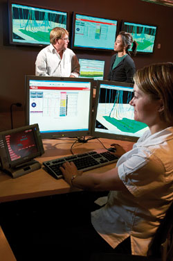 |
Fig. 4. Carmen Lee, CNRL geologist, Dan McKain, CNRL Drilling superintendent and Tammy Moores, geosteering expert collaborate in Halliburton’s Real Time Operations Centre.
|
|
Halliburton developed a unique methodology for geosteering in Primrose field. First, control data gathered from offset wells, along with interpreted subsurface geological features, was assembled in a 3D shared earth model. Drilling engineers, geologists and directional well planners then designed well and pad plans for optimal reservoir drainage. Building from the earth model, the team developed a petrophysical model to predict log response along each well path. This model acts as the driller’s real-time roadmap.
During the drilling operation, electromagnetic telemetry transmits downhole data from logging-while-drilling (LWD) tools back to the surface and then by satellite to the RTOC. There, a data portal displays the resistivity and gamma ray logs, as well as drilling and operational data. Experts continually compare the LWD data against the predicted log response in the geosteering model to estimate the wellbore’s proximity to the target horizon. The team then updates the model, plans the new drill-ahead targets and communicates them to the directional driller at the well.
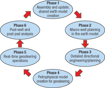 |
Fig. 5. A six-phase process continually updates the earth model.
|
|
REAL TIME
CNRL and Halliburton developed the team and the workflow over several months before launching operations. The team approached the first two wells as a learning experience, since CNRL planned to drill dozens of field wells over the next 10 to 15 years. One of the drilling challenges is speed. Unlike drilling hard rock at a comfortable pace, the drill bit cuts through the Clearwater sand at 200 – 400 m/hr. The bit can shoot out of control and dive several meters into the rock before anyone realizes what has happened. Changes in inclination must be swift, but subtle. At this speed, correct real-time decisions need dynamic modeling tools, real-time interpretation and an experienced geosteering team.
Quickly interpreting geology at the drill bit was a breakthrough. Clear communication was complicated by the six disciplines involved in “on the fly” decisions during drilling. CNRL and Halliburton developed new ways of working and thinking to communicate effectively to the right people with the right information at the right time in the right way. It was helpful to establish clear communication and operational protocols to ensure everyone understood their role.
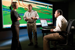 |
Fig. 6. Carmen Lee, CNRL geologist, Dan McKain, CNRL drilling superintendent, Herschel Foster, Halliburton geosteering expert work to update the 3D earth model in the visualization center.
|
|
Another major adjustment was learning to trust the data and the tools. The resistivity logging tool was originally designed to detect oil and water while drilling vertically through carbonate deposits. Applied horizontally, it can investigate two meters vertically in either direction. While CNRL’s geologists expected the tool to detect shale, they were surprised to discover that it also distinguished between producing sands, nonproducing sands and muddy sands.
As the geologists saw the expected reservoir characteristics, they gained confidence in the tool. Although a geologist was stationed at the wellsite while the first two wells were drilled, the tool data made this unnecessary. As engineers saw that the wellbore was being placed on target, they doubled the penetration rate from 150 m/hr to more than 300 m/hr. One factor helped everyone: CNRL launched geosteering where it already had a high drilling density and reservoir knowledge.
On the first well, the team failed to achieve the geological control they had wanted. The improved data quality showed that the reservoir was not formed as the earlier models predicted. The geosteering engineers re-cast the earth model and the directional profile with the new information, then recalibrated the tools.
| |
Real-time drilling of a Primrose well |
|
| |
The 4A52 well, Fig. 7, is a typical well drilled in CNRL’s Primrose field. CNRL’s asset team worked with well planners to develop a theoretical well plan from predictive geology. This original plan served as the baseline for a petrophysical model. The three-dimensional petrophysical model, created with StrataSteer 3D software, predicted the LWD responses expected while the well was being drilled. With this knowledge, the geosteering engineers could better understand and interpret downhole events to make decisions during drilling.
In Well 4A52, the original, theoretical plan was quite different from the well that was actually drilled. In a sense, that was the goal: to place the wellbore at the optimum position based on real geology – not on a fixed plan.
The drillers landed the well to the intermediate casing point at 89.6° from LWD readings that indicated the bit was 1.5 m above a non-reservoir zone. As the data was received in the RTOC, it was correlated with the model, which was then adjusted to reflect the real geology. Based on this updated model, engineers adjusted the planned drilling targets slightly to approach the muddy sand, and then communicated these new targets to the directional drillers at the wellsite. These targets are the red dots along the well path in Fig. 7. Each represents three measurements: a true vertical depth (TVD), a north coordinate and an east coordinate. The goal of each target is to bring the well to within approximately one meter of the base of the producible part of the reservoir.
It was the directional driller’s task to determine how to reach the new target. After determining that the target was mathematically and operationally achievable, the driller took into account the dogleg severity, the torque or drag ramifications and the output capabilities of his equipment to drill to the new target. The total elapsed time, from setting a target to drilling action, was about three minutes, and did not slow the process.
 |
Fig. 7. This interactive geological/ petrophysical 3D model shows model resistivity (top), actual resistivity (second from top), gamma ray (second from bottom), the path of Well 4A52 overlaid on the formations, including shale (green), non-reservoir (brown) and reservoir (yellow).
|
|
The driller proceeded horizontally toward the target to 730 m, where a separation on the resistivity readings showed that the tool was approaching the muddy sand. The model indicated that the formation was beginning to rise, so the targets were again adjusted to climb in TVD. At 950 m, the LWD measurements dropped, signaling that the sensor was approaching the base of the reservoir. The geosteering engineers communicated a new target to the driller, who steered upward again to avoid drilling into non-reservoir sands.
The resistivity measurement suddenly spiked and the well path deflected sharply downward when the bit hit a calcite stringer at 1,145 m and again at 1,210 m. The driller quickly regained control. While drilling through sand at 200 – 250 m/hr, bits can travel some distance before drillers can turn them. For this reason, the Canadian drillers have learned to incline the bit more subtly than for other environments. The operation continued until the well neared the total depth. Targets were adjusted one final time to accommodate an unexpected downward dip in the formation.
From start to finish, the horizontal portion of the well, from 633 – 1,876 m, was drilled in about 11 hours.
Once the well was drilled, the team ran a 168 mm production liner assembly, to ensure maximum reservoir drainage. The well will be produced with an insert beam pump placed in a pre-designed 30-m tangent section at 85° in the intermediate build section.
|
|
|
RESULTS
The 55 geosteered wells were drilled with zero sidetracks, straighter wellbores and wellbore placement within 0.5 – 1 m from the reservoir base. The new wells require several months of steam injection to melt the bitumen into the horizontal well, so they are not yet in production. Production is expected to rise and recovery to improve. By consistently placing wells less than one meter above the bottom, CNRL has increased its producible reservoir by 5 – 10%.
CNRL achieved an average drilling cost reduction of 13% per well, which more than paid for the cost of real-time geosteering. The lower costs are partly due to faster drilling speeds. Another contributor is the time saved by avoiding the shale. In addition, the smoother well trajectory reduces drilling costs, while maximizing steam contact with the reservoir. The straighter wellbore requires fewer wiper trips, creates easier liner and casing runs, and smoothes other drilling operations. As a result, the number of days in horizontal section fell from 4.25 to 3.6 and drilling time declined 40% in some wells. In addition, the cost of a wellsite geologist was eliminated.
While much time was spent preparing for the project before drilling the first well, the more efficient workflow shortens CNRL’s planning time. Engineers once took 4 – 6 weeks to complete a well plan; that plan now takes days using the shared earth model.
One other hoped-for result of geosteering remains: the possible reduction in the number of stratigraphic test wells required by the Alberta Energy and Utilities Board. CNRL must drill four vertical wells per section to gather technical data on reservoir properties. With the increase in reservoir information captured through the RTOC horizontal drilling program, the company could request the board to reduce that requirement.
CNRL’s senior management is pleased with the results of the real-time geosteering project and is willing to take it to the next level. The company plans to use the RTOC approach on similar properties east of Primrose field. 
ACKNOWLEDGEMENT
The authors thank several individuals for their contributions to this article and to the Primrose geosteering project: Dan McKain, CNRL drilling superintendent; Scott Gair, CNRL production engineer; Herschel Foster, Halliburton formation evaluation technical advisor; Tammy Moores, Halliburton geosteering geologist; Bob Wytsma, Landmark senior technical consultant; Matt Crane, Halliburton directional driller; Keith Sanford, Halliburton technical professional; and Mo Shehada, Halliburton M/LWD senior technical advisor. In addition, the authors wish to thank all members of the CNRL/Halliburton team who contributed to the Primrose project both in the Calgary RTOC and at the wellsite.
THE AUTHORS
|
| |
Carmen Lee is a geologist in CNRL’s thermal operations group.
|
|
| |
Darcy Cuthill is manager of Halliburton’s Real Time Operations Centre in Calgary, Canada.
|
| |
|
|

