|
|
|

By Petroleum Technology Transfer Council |
Airlift pumping reduces costs, boosts revenue in Illinois stripper wells
Frequent failures, lost output and high costs have been cut significantly by replacing conventional rod pumping with an airlift pumping system in Illinois basin wells.
Dennis R. Swager, Team Energy, LLC, and Dan Roberts, Airlift Services International
Significant corrosion and scaling problems in two shallow Illinois basin oil wells operated by Team Energy, LLC (Team), led to frequent failures, lost production and high operating costs with conventional rod pumping systems. In January 2004, Team replaced the rod pumps with Airlift Services International’s (ASI’s) airlift pumping systems. The airlift system uses compressed air or gas to lift fluids through a series of alternately filled and emptied stages of plastic tubing and stainless steel.
Team now has some 20 months of operating experience with the airlift systems. In the operator’s Mieure 13, operational results have improved, and cash flow has increased by about $1,960/month. Thanks to significantly less downtime, average monthly production has increased by about 30 bbls of oil. Fluid volume and pumping fluid level in the second well, Hardacre 5, exceeded initial design capacity, which led to several design enhancements.
The enhanced system has operated reliably since January 2004. When the Hardacre 5 was pulled in July 2005, about 15 months after correcting a corrosion issue, little corrosion or wear was evident in the system. Airlift pumping lowered overall operating costs and increased output as compared to conventional pumping systems in these two Illinois basin wells.
THE PROBLEM
The test sites were Team Energy’s two most problematic wells in Lawrence County, Illinois. Excessive failures were due to severe corrosion and scaling tendencies. High, suspended solid volumes were also a problem in one well. Using traditional rod pumps, these wells were not profitable. Operator personnel field-tested the airlift system, because it minimizes negative effects of scaling, corrosion and wear, in hopes of increasing runtime and reducing pulling expenses.
AIRLIFT PUMPING SYSTEM
The Airlift Fluid Pumping System is a series of fluid chambers that are connected by line assemblies, Fig. 1. Fluid is raised in the line assemblies that contain two gas or air lines connected to alternate chambers, Fig. 1, step 1. Compressed gas or air can be used as the working media; the test wells used air.
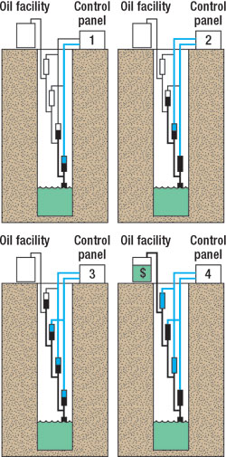 |
Fig. 1. Airlift operation schematic.
|
|
The closed design assures that no air is released in the wellbore. The control panel first applies air at a pre-set pressure (150 psi) to the top of odd-numbered chambers through the internal control lines. It simultaneously vents the pressure from the even-numbered chambers through the other internal control lines, Fig. 1, Step 2. The pressurized gas or air in the odd chambers displaces the fluid, causing it to flow to the even chambers directly above them, with check valves preventing any downward flow.
The control panel then directs pressurized air to the top of even-numbered chambers, and simultaneously vents the pressure on odd-numbered chambers, causing fluid to rise from the even chambers to the odd chambers above them, Fig. 1, step 3. When the lowest fluid chamber is empty and vented, fluid will flow back into this chamber by gravity, as well as reservoir pressure from the well, preparatory to repeating the process. The fluid inlet and bottom fluid chamber must remain below the well’s fluid level. Fluid reaching the surface flows into the production facility, Fig. 1, step 4.
Cycle times and pumping capacities vary and are dependent on the well depth, reservoir deliverability (recharge time), static and pumping fluid levels, specific gravity of the fluid, oil cut, suspended solids, temperature and other factors. Airlift systems have operated as deep as 2,300 ft., and have demonstrated rates as high as 200 bopd at depths of less than 1,000 ft. Materials used are designed for bottomhole temperatures up to 170°F. A typical installation in a 1,000-ft well will require compressed air or gas flow rates of about 30 to 50 cfm.
FIELD RESULTS/ EXPERIENCE
As alluded to earlier, two of the operator’s most troublesome wells were selected for test installations. Both wells have seen noticeable improvement.
Mieure 13. Equipped with a rod pumping system at the time of the airlift test installation, Mieure 13 had a history of monthly rod, tubing and pump failures. This well was Team’s most costly to operate, confirmed in an annual review by Nalco Energy Services. It was also the most problematic well. Since the installation in January 2004, the well has not been pulled. See Table 1 above for operational improvement detail.
Hardacre 5. An airlift pumping system was installed in this well during January 2004. It was shut-in after being pulled six times in 2003 and five times during 2002. It was Team’s second most costly well to operate. Airlift and Team worked closely on this well, and it served as a test site for system development. Since installation, the well has been pulled five times to make design enhancements and test alternative configurations.
ECONOMIC CONSIDERATIONS
Total costs for the airlift systems, including the compressors, were $17,000 (Mieure 13) and $18,000 (Hardacre 5). This compares to about $14,000, each, if the wells had included new rod pumping equipment. Therefore, payout for the Mieure 13 would be three months or less. Payout for Hardacre 5 is not as straightforward, because several pulling jobs were associated with enhancing the airlift design, but it would be about four months. Team continues to monitor the systems’ operation and will consider using additional installations in future wells.
Team President Dennis Swager said, “The ASI systems worked successfully in these two experimental applications by increasing cash flow from expense savings and increased production.”
OTHER INSTALLATIONS
The first airlift system was developed and installed by John Marvel in northern Indiana during 1995. The system was commercialized in 2003. ASI has installed 16 systems in five states (Indiana, 7; Texas, 4; Illinois, 2; Kentucky, 2; West Virginia, 1).
These systems range in depth from 1,000 ft. to over 2,300 ft. Total fluid rates range from 1 bpd to 109 bpd. One of the system applications was in a natural gas producing well. Output from this well powered the gas compressor. Only the engine fuel was taken from the production stream. Another application being installed is in the Ohio River flood plain. These pumping systems will be operating underwater during periods of flooding. The pumping system is designed for, and will operate underground, significantly reducing environmental impact. 
THE AUTHORS
|
| |
Dennis R. Swager is president of Team Energy, LLC, an independent E&P company in Bridgeport, Illinois, that operates about 250 oil wells in Illinois and Indiana. Mr. Swager is also president of Swager & Associates, Ltd., an energy consulting business supplying geologic, engineering and operational management services. He holds BS and MS degrees in geology from the University of Kentucky. swager@teamenergyllc.com.
|
|
| |
Dan Roberts, president and CEO of Airlift Services International, started his career as an engineer at Delphi, Inc., and worked his way to an executive position. He has started up several companies, has extensive technology and product experience, and has worked internationally. He also runs a research company, R&R Consultants. Mr. Roberts holds a BS in electrical engineering and an MBA in International Finance. info@airliftservices.com.
|
| |
|
|