|
|
|

By Petroleum Technology Transfer Council |
MPD well taps light oil in deep Monterey Shale
A 10,000-ft horizontal well drilled in 2004 in southern California with DOE support using Managed Pressure Drilling demonstrated the practicality of developing the Monterey Shale with horizontal boreholes.
Bob Knoll, Maurer Technology Inc., Subsidiary of Noble Corp.
Below 10,000 ft, a horizontal well was drilled onshore southern California using novel Managed Pressure Drilling (MPD) technology to horizontally access over 2,200 ft of fractured, light-oil Monterey Shale with a concentric-string, air-injection system and a simple water-based, drill-in fluid. The MPD method and drill-in fluid design provided good Evaluation-While-Drilling (EWD) capability, faster penetration and minimal formation damage concerns.
Altered casing design and water-based fluids proved successful in mitigating problematic unstable shale sections in the intermediate and upper curved section of the well. PDC bit application provided superior performance potential vs. rock bits in both intermediate and productive intervals. Drilling time and cost exceeded pre-well estimates; however, with more intense procedural planning and application of the typical site-specific learning curve in field operations in the future, costs for similarly designed wells in this setting could be significantly reduced.
BACKGROUND
The well, drilled by Temblor Petroleum Co. LLC, was supported by the US Department of Energy, National Energy Technology Lab, under the “Demonstration Well” program. The objective was to demonstrate that a deep fractured Monterey reservoir in California’s Santa Maria basin can be developed using cutting-edge horizontal and MPD drilling methods. Two prior conventional vertical/ sub-vertical wells drilled with heavy mud were non-commercial after fracture stimulation, even though both had strong drilling shows, and free oil and gas were recovered during and after completion.
Seismic and well data indicate a structural trap of some 1,500 acres, providing a potential accumulation of 30 to 50 MMbbl of 31° API oil, and 30 to 50 Bcf gas. The new well, Castillo, Ross and Howe 2-19, drilled in the fall of 2004, is located in S19-T8N-R32W in Santa Barbara County. The target high-resistivity section of the Monterey is at a depth exceeding 10,000 ft TVD. All commercial onshore production from this formation is at much shallower depths, i.e., +/ – 5,000 ft TVD.
The original discovery well, drilled in 1986, penetrated and logged approximately 700 ft of a light-oil column at 10,500 ft TVD. Temblor directionally drilled a second delineation well (30° angle) in 1999 from a new surface location 0.5 mi southeast of the discovery well’s surface location, with a bottomhole location terminated within 400 ft laterally displaced from the discovery well in the target interval.
The “high resistivity” member of the Monterey is a gradation between chert, argillaceous chert and siliceous shale, and thought to be the highly fractured zone. The bounding upper and lower Monterey units are less siliceous. The second well logged the same oil column with no evidence of bottom water or top gas, and flowed for a short period (10 bopd for 1.5 hr). The well would not sustain commercial flowrates after an acid stimulation, and was suspended.
High mud weights were required to hold back the massive (+/ – 4,000-ft thick) problematic “Sisquoc” shale above the Monterey. Stability problems led to cost overruns in both previous wells, and were seen as a well construction challenge in the demonstration well. There were also concerns about damage if high-mud-weight systems were used. Successful exploitation of this structure by horizontally accessing vertical fractures in a non-damaging mode was expected to yield about 600 bopd.
DESIGN ASPECTS/ RESULTS
The new well employed many novel design attributes and MPD procedures to: avoid a damaging process; mitigate unstable shale problems; provide faster penetration rates; and allow simple EWD observation of oil-filled fracture access.
One novel attribute of the well is related to the 10.75-in. surface casing and 7-in. concentric slave string design. The term “slave” refers to an extra concentric casing string suspended from the wellhead. This string was stabbed into a 7-in. liner that had been run and cemented at the heel of the well at 10,000 ft TVD and 60° angle. The liner hanger was set at 3,300-ft TVD just inside the surface casing shoe, Fig. 1.
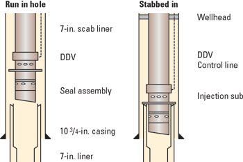 |
Fig. 1. Slave string and downhole deployment drive (DDV) design/ placement.
|
|
The slave assembly included a ported sub directly above the liner stab-in assembly. This design provided a temporary annular flow path for air-lift injection, and an area for secure placement and control of a downhole deployment valve (DDV) set directly above the ported sub. The DDV, when function closed, would allow conventional tripping above the valve while maintaining the horizontal interval in a balanced/ underbalanced bottomhole-pressure (BHP) condition. Once the productive interval was being drilled in a controlled MPD mode, the slave/ DDV assembly was retrieved and the 7-in. liner was conventionally tied back to the surface wellhead.
This approach provided capability for concentric string air-injection MPD without the requirement of special motors/ MWD equipment or practices necessary when conducting conventional underbalanced drilling with aerated fluids. Air provided significant cost savings vs. nitrogen. This worked well in drilling the horizontal section once optimum air-injection rates were established. The reservoir pressure was expected to be near 5,000 psi. The targeted BHP range of around 4,600 psi was generated and maintained during drilling. Improved penetration rates occurred with reduced BHP, as clearly seen in Fig. 2, where instantaneous drilling rate, air-injection rate and corresponding reduced BHP observations (from an MWD annular pressure sensor) are illustrated.
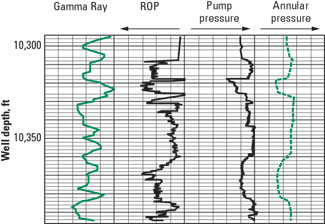 |
Fig. 2. Rate of penetration response to reduced bottomhole pressure.
|
|
FLUID SELECTION
A costly oil-based mud (OBM) was initially considered necessary in the intermediate vertical and upper curve-to-heel section, to mitigate shale stability problems. The larger-than-normal intermediate hole size – 9.825-in. vs. the more standard 8.5-in. hole for 7-in. liner – allowed by the larger surface casing, provided an enlarged annular clearance for the 7-in. liner. This, in turn, allowed use of a simple pre-weighted, water-based fluid in the intermediate hole section. This approach proved viable as the Sisquoc shale was exposed for more than 17 days prior to liner installation, and the 7 in. was run to bottom with little trouble. The use of water-based fluid in both the curve and horizontal section also proved very valuable in terms of EWD hydrocarbon observation.
A seismic abnormality suggests a fault or fractured zone may exist at the top of the Monterey target. Penetration rate and mineralogy variations and strong hydrocarbon shows all pointed to an oil-filled fractured zone at this point. The upper curve was terminated and lined with 7-in. liner. The 6.125-in. horizontal section was placed and completed openhole, employing a short tangent section in an attempt to get deeper into the high-resistivity interval of the shale, and a lower curve built to 90° angle, and a horizontal section drilled to beyond the discovery well’s bottomhole location.
A basic challenge was stabilizing the Shale to protect the integrity of the hole and to allow cuttings to come to the surface in good condition to allow EWD, which involves visual inspection of the drilled cuttings for micro-fracturing and oil within the fractures, and is calibrated with mud-gas logging observations, penetration rate changes, etc.
Typically, this is accomplished by adding 4% KCl to the drilling fluid. This causes corrosion, which is accelerated with air injection. This much KCl also leads to special drilling waste disposal requirements. The problem was successfully resolved by using a KCl substitute, TEA (tri-ethylene methyl-chloride). With TEA, extensive use of corrosion inhibitors is avoided, providing considerable cost savings. There was no apparent corrosion of the drill pipe. Hole conditions were good in the productive/ horizontal interval; and the cuttings, while very small, did not appear to be significantly hydrated or altered.
With a water-based fluid, drilled oil and mud-gas spikes were readily evident as fractures were crossed. A gamma-ray sensor employed in the horizontal section was less effective in detecting fracture crossings. The midsection of the lateral appeared void of fracture crossings, while the far end accessed multiple fractures as it passed the original well-bottom location.
FIELD PERFORMANCE/ CONCLUSIONS
The plan was for 39 days with a cost of $2.4 million. The well actually required 66 days, and cost $3.4 million. Fig. 3 illustrates how the actual well path was lower in the reservoir than planned. Once completed, the well failed to inflow and only minor amounts (a few barrels) of light oil were recovered. The lack of production may suggest that actual sustainable reservoir pressure is far less than anticipated. It may also be that the well path fell below the high-resistivity member where the fractures are concentrated. The operator is currently investigating the viability of re-entering to log and stimulate the well. The productivity potential of the well is not yet fully defined.
 |
Fig. 3. Planned and actual well paths.
|
|
Time sheets indicate that the total “problem time” on the well accounted for only 3.8% of field operations. From the author’s perspective, there was a larger proportion of time lost due to avoidable errors made onsite. This illustrates that very stringent focus is required to ensure key staff continuity between planning and field operations phases. Properly briefed and adequately relieved field supervision providing 24-hr coverage and detailed procedures is a necessity when conducting novel well operations. 
ACKNOWLEDGMENTS
This work was conducted with the support of the US Department of Energy under Award No. DE-FC26l-03NT15426. However, any opinions, findings, conclusions or recommendations expressed herein are those of the author and do not necessarily reflect the views of the DOE. The author would also like to thank the operator, and the Petroleum Technology Transfer Council (PTTC), particularly Lance Cole, for their support in allowing this field experience to be presented.
THE AUTHOR
|
 |
Bob Knoll, a graduate geologist from Nova Scotia, has worked in a variety of positions on the well construction and production side of the offshore industry. He is senior consultant and technical training manager for Maurer Technology Inc., and has over 30 years of drilling, R&D, and technical training experience. The last 14 years have been focused on project management, technical training, and product and services marketing of horizontal/ complex, multi-branch and MPD drilling/ completion technology. He delivers numerous training programs for Petroskills, SPE, CIM, AAPG, etc., and conducts internal asset team workshops for operators, service providers, regulatory bodies and other stakeholders globally.
|
| |
|
|

