Completion Methods
Advanced hydraulic fracture diagnostics optimize development in the Bossier sands
A series of studies for Anadarko Petroleum on the Bossier formation optimized frac treatment designs and improved well economics. Two-stage frac jobs resulted in better output than single-stage efforts.
Stephen Wolhart, Pinnacle Technologies, Houston
Anadarko Petroleum Corp. has conducted a series of studies to improve field development and stimulation practices in the Bossier formation of East Texas. Advanced hydraulic fracture diagnostics were used to better understand fracture geometry and well performance. The objective of the diagnostics was to measure hydraulic fracture geometry, improve estimates of propped fracture length and optimize fracture designs.
Diagnostics included microseismic and surface tiltmeter fracture mapping, radioactive tracer logging, production logging, fracture modeling, pressure buildup testing and production data analysis. As a result, changes have been made to completion and stimulation design, resulting in improved well performance.
BOSSIER OVERVIEW
The Bossier play is on the western flank of the East Texas basin, Fig. 1. Bossier wells generally produce dry gas from overpressured sands contained within the Bossier shale.1 Productive sands are found at depths from 12,000 to 15,000 ft and generally occur in the upper 500 to 600 ft of the Bossier shale.
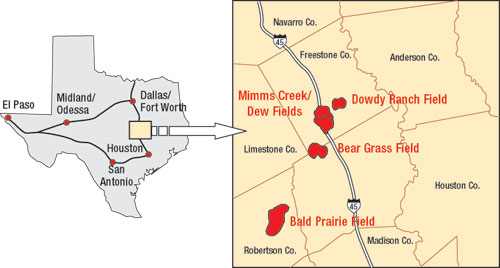 |
Fig. 1. Location of the Bossier play in East Texas.
|
|
Five separate sand units (Taylor, Shelly, Moore, Bonner and York) have been identified. They are found as lenses, segregated pods and channel trends. Reservoir heterogeneity is high (Fig. 2), which shows logs from three wells in Dowdy Ranch field. The APC Anderson 2 and APC Anderson 3 wells are only 495 ft apart, but the thickness of the Bonner and York sands changes significantly between these wells.
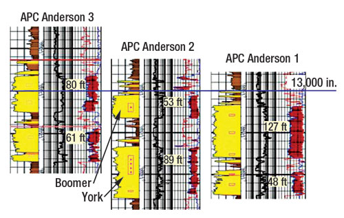 |
Fig. 2. Logs from three Bossier wells in Dowdy Ranch field.
|
|
Porosity in these sands varies from 6% to 20%. Permeability ranges from 0.001 md to 1 md but is usually below 0.1 md. The upper three sands, Taylor, Shelly and Moore, are typically of lower reservoir quality than the Bonner and York. Gas has been produced from the Bossier since the 1970s, but current activity began in 1996 and ramped up in 1998. Anadarko is the most active operator in the Bossier, but other operators work this area, as well. All producing wells drilled in the Bossier are hydraulically fractured. Stimulation is key to the play’s economics.
Water fracs and hybrid fracs are common stimulation methods in many low-permeability reservoirs. These treatments involve creating fractures, using slickwater rather than cross-linked gels. The proppant is carried into the fracture, either with a gelled fluid (hybrid frac) or slickwater (water frac). The theory is that low-viscosity pad fluids result in longer, more confined fractures. However, low fluid viscosity can result in poor proppant placement, and narrower fractures can cause proppant bridging. Both water fracs and hybrid fracs have been used in the Bossier.
There have been five stages in the evolution of frac design in the Bossier:
- Early wells were stimulated with conventional cross-lined gel and sand treatments. These wells produced about 12,000 cfgd per net foot of pay during the first six months online. Job cost ranged from $200,000 to $350,000. Other treatments were evaluated, due to marginal well economics.
- The next set of wells was treated with water fracs without proppant. Output rate for these wells was initially higher, but rates dropped quickly as the fracture began to close. Overall, well economics did improve with these inexpensive ($50,000-to-$100,000) treatments.
- Wells were then treated using water fracs and 20/40-mesh sand as proppant. Output rates increased, and treatment costs ranged between $100,000 and $150,000.
- The next evolution was to pump water fracs with 40/70-mesh sand as proppant. Proppant and slickwater were pumped in alternating stages. Total proppant volume was typically 200,000 lbs. Well economics improved again, with long-term production averaging 16,000 cfgd per foot of net pay. Costs were similar to previous water frac treatments with 20/40-mesh sand.
- The final treatment type has been the hybrid frac. Slickwater is pumped first to generate length, followed by a cross-linked gel pad and then by the proppant stage with 20/40-mesh sand with cross-linked gel. Cost for these jobs typically ranges from $175,000 to $225,000. These wells have long-term output rates of about 18,000 cfgd per foot of net pay.
HYDRAULIC FRACTURE MAPPING
Pinnacle Technologies performed microseismic imaging to measure overall fracture geometry on four wells during 2001 and 2002. Two of the mapping wells were stimulated with water fracs, and two were stimulated with hybrid fracs. Microseisms are micro-earthquakes induced by changes in stress and pressure associated with hydraulic fracturing.2 These earthquakes are slippages that occur along pre-existing planes of weakness (e.g., natural fractures) and emit seismic energy that can be detected at nearby seismic receivers.
With an array of tri-axial receivers situated at depth, near the hydraulic fracture, compressional (primary or P) and shear (secondary or S) waves can be detected. The location of any individual microseism is deduced from arrival times of the P and S waves (provides distance and elevation) and from particle motion of the P-wave (provides azimuth from the receiver array to the event).
To use the particle motion information, it is also necessary to orient the receivers. The orientation is typically performed by monitoring perforations, string shots or other seismic sources in the treatment well or some other nearby well. Accurate location of microseisms, and thus the fracture image, is strongly dependent on accurate information about the velocity structure.
Since microseisms are extremely small, a sensitive, high-rate telemetry system is required to obtain accurate results. To meet these requirements, a 12-level, three-component, retrievable geophone array is deployed using a fiber optic wireline unit. Once at depth, the receivers are clamped against the wellbore with mechanical arms. The tool string is designed with an aperture to adequately cover the target zones. Treatments are continuously monitored, to determine how the fractures grew with time. This is critical for understanding complex fracture growth. To improve project results, cross-well velocity data were directly measured using a perforation-timing procedure.3
Results from one well, Anderson 2, are reviewed in detail in this article. This job utilized a single microseismic imaging well (Anderson 1) to monitor treatments in the York and Bonner sands. Anderson 2 has 89 ft of pay in the York, which calls for a large-sized treatment. The design volume of 300,000 lbs of 20/40 proppant was successfully placed using a 35# borate, pumped at an injection rate of 35 bpm.
Rates for hybrid jobs in this area are usually 45 bpm, but in this case, the lower rate was used to keep the fracture better confined to the pay interval and to reduce horsepower charges. The job showed a significant net pressure gain of about 1,000 psi, suggesting confined fracture growth and increasing fracture complexity as the job progresses.
Microseismic mapping results for the York stimulation are shown in Fig. 3 (plan view) and Fig. 4 (side view). The fracture azimuth is N91°E, with asymmetrical length growth 550 ft to the west and 275 ft to the east. Events were observed in the Bonner, indicating the treatment grew out of zone. Reviewing fracture growth with time, it was apparent that communication between the York and Bonner was, at a single point, about 300 ft out along the fracture’s west wing.
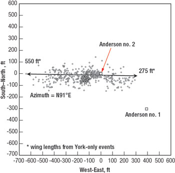 |
Fig. 3. Plan view of microseismic events from the APC Anderson 2, York frac.
|
|
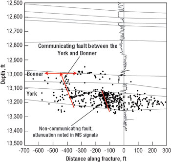 |
Fig. 4. Side view showing microseismic events from APC Anderson 2, York frac.
|
|
From there, the fracture grew up and extended, back to the wellbore and farther to the west in the Bonner. Communication based on this information appears to be through a fault. Main portion of the fracture treatment, except the portion attributed to the fault, was contained within the York sand.
The Anderson 2 has 53 ft of net pay in the Bonner, and a smaller job design, 175,000 lbs of 20/40 proppant, was used. Once again, a 35# borate gel was used in the crosslinked stages. Net pressure gain was more than 1,000 psi. In comparison to the York treatment, most of the net pressure rise comes almost immediately after proppant arrives on formation, indicating a possible near-wellbore width restriction in the fracture.
The relatively steep pressure increase, and the instantaneous reaction to proppant, indicate that this is not a tip screen-out. Given the risk of a screen-out with bottomhole gauges in the hole, it was decided to call flush early, placing only 135,000 lbs of the designed 175,000 lbs into the created fracture.
Like the York treatment, the Bonner fracture grew east/ west with an azimuth of N87°E. Fracture length growth was again asymmetrical, with an east wing extending 475 ft and a west wing of 175 ft. The Bonner treatment was observed to have communicated upward, with growth into the Moore and Bossier Marker sands through a fault. For the Bonner stimulation, a significant amount of the treatment appears to have gone out of zone.
Both fractures grew in the east/ west direction. Two separate faults were identified, as seen in Fig. 5. For the York, the closest fault to the wellbore appears to be non-communicating. However, it still appears to have generated a significant amount of microseisms (flaws associated with the fault) near the fault, along with attenuated microseismic signals that cross the fault from the far wing. The second fault is open during the stimulation and communicates upwards to the Bonner. The hydraulic fracture in the York sand continues to grow westward beyond the second fault intersection.
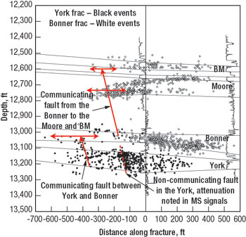 |
Fig. 5. Side view showing combined microseismic results for APC Anderson 2.
|
|
For the Bonner stimulation, the fault closest to the wellbore was open during the stimulation and is responsible for upward communication to the Moore and Bossier Marker sands. Note that this is the same fault that was observed to be non-communicating at the York level on the first stimulation. Westward growth of the fracture in the Bonner appears to have been arrested, where it intersected the fault. The Bonner fracture does not extend to the second fault observed during the York stimulation.
Table 1 summarizes mapping results for all four wells. Fractures grew in a general east/ west direction, with fracture half-lengths varying from 170 ft to 750 ft. Surface tiltmeter mapping was performed previously in the Bossier, also showing an east/ west fracture trend.4 Fracture asymmetry was observed and might be due to structural features in the reservoir, depletion in offset wells or the lenticular nature of Bossier sands.
| |
TABLE 1. Summary of Microseismic Mapping |
|
| |
Well |
Interval |
Fracture
azimuth |
Fracture height
growth |
Zone
coverage |
Fracture
length, ft |
|
| |
|
|
| |
Well A |
York |
N 90° E |
Contained |
100% |
480 to W |
|
| |
|
|
|
|
|
320 to E |
|
| |
|
|
| |
Well B |
Bossier |
|
|
|
|
|
| |
|
Marker |
|
Upward growth into the |
|
615 to W |
|
| |
|
Moore |
N 81° E |
Cotton Valley |
100% |
750 to E |
|
| |
|
|
|
| |
|
York |
N 81° E |
Contained |
86% |
325 to W
25 to E |
|
| |
|
|
| |
Well C |
York |
N 82° W |
Upward growth into the Bonner and Cotton Valley (fault-related) |
60% |
420 to W
170 to E |
|
| |
|
|
| |
Anderson 2 |
Bonner |
N 87° E |
Upward growth into the Moore and Bossier Marker (fault-related) |
100% |
475 to E
175 to W |
|
| |
|
|
|
| |
|
York |
N 91° E |
Upward growth into the Bonner (fault-related) |
100% |
550 to W
275 to E |
|
|
Fracture height growth in the Bossier was fairly complex. Out-of-zone growth was observed in two wells but was not the result of conventional fracture height growth. Microseismic mapping results in Anderson 2 and Well C showed fracture growth along faults, resulting in communication between sands. Fracs were usually contained in the Bossier sands, except when faults were encountered. However, Well B did indicate fracture height growth up through the bounding shales, clearly generating microseisms in the shale layers.
PRODUCTION RESPONSE AND WELL TESTING
Anadarko put considerable effort into studying production results of wells in the Bossier. The production response for 18 wells completed in the Bossier was evaluated using a combination of decline curve analysis and pressure buildup testing.5 Results are shown in Fig. 6. The hybrid frac treatments have generated longer, effective fracture half-lengths than either the small or large water fracs. Average effective fracture half-length was 70 ft for small water fracs, 100 ft for large water fracs and 235 ft for hybrid fracs. Similar improvements in fracture conductivity were seen with hybrid fracs.
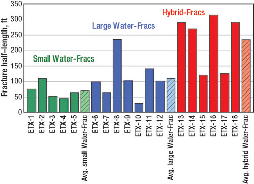 |
Fig. 6. Effective fracture half-lengths for 18 Bossier wells, based on production data analysis and pressure buildup testing.
|
|
Production data analysis on the Anderson wells showed similar results.6 After stimulation, the Anderson wells were put onstream. When production of frac-water from the fracture stimulation declined, a production log was run in Anderson 2. Production log results showed that 34% of the output was from the Bonner and 65% from the York, with a small amount from a shale interval that was stress-tested.
These percentages matched up very closely to percentages of net pay each zone had for the total stimulated interval, indicating effective stimulation of both sands. Cumulative production of Anderson 2 has been 30% greater than that from Anderson 1, which had 19% more net pay. This shows that stimulating the Bonner and York in two stages probably had a large impact on the effectiveness of treatments, and thus, the well’s productivity.
A two-week pressure buildup test was run in Anderson 2, once output had dropped to about 1.5 MMcfgd. Pressure transient analysis was performed to estimate propped fracture half-length for comparison with those from microseismic imaging. The calculated effective fracture half-length was about 220 ft. This is similar to results from other hybrid fracs in the Bossier, and is a great improvement over what was achieved with previous types of fracs (water fracs or gel fracs). The effective propped half-length of 220 ft is shorter than the created frac half-length of 400 to 500 ft measured by microseismic imaging.
CONCLUSIONS
Anadarko has used a series of studies on the Bossier formation to optimize fracture treatment designs and improve well economics. Among the findings from this effort are:
- Two-stage fracture jobs resulted in better output rates than single-stage jobs, because both sands are more effectively stimulated.
- Effective fracture half-lengths for hybrid fracs are longer than the effective fracture half-lengths obtained from either cross-link gel or water frac treatments. Propped frac half-lengths were derived from pressure buildup analysis and history-matching production data.
- Microseismic hydraulic fracture mapping was successfully used to measure fracture geometry and growth with time in the Bossier.
- Hydraulic fractures typically grow east/ west in this area.
- Microseismic data indicate created fracture half-lengths of 400 to 500 ft. Propped or effective fracture half-lengths derived from pressure buildup and production data were significantly shorter than created frac half-lengths.
- Faults can have significant impact on fracture growth. Out-of-zone fracture height growth in this area is primarily the result of faults.
- Fracture mapping shows that hydraulic fractures can grow through faults (faults are not necessarily barriers to hydraulic fracture growth). Anderson 2 microseismic mapping shows an example of both a barrier fault and a fault that acts as a leak.

ACKNOWLEDGMENT
The support of Anadarko Petroleum Corp. is gratefully acknowledged. Special thanks to Richard Sullivan with Anadarko for his leadership during this project. Some funding was provided by the Department of Energy – National Energy Technology Laboratory (Contract #DE-FC26-01NT41326).
LITERATURE CITED
1 Montgomery, S.L. and R. Korlewicz, “Bossier play has room to grow,” Oil & Gas Journal, pp. 36 – 43, Jan. 29, 2001.
2 Warpinski, N. R., S. L. Wolhart and C. A. Wright, “Analysis and prediction of microseismicity induced by hydraulic fracturing,” SPE paper 71649, SPE Annual Technical Conference & Exhibition, New Orleans, Louisiana, Sept. 30 – Oct. 3, 2001.
3 Warpinski, N.R, R. B. Sullivan, J. E. Uhl, C. K. Waltman and S. R. Machovoe, “Improved microseismic fracture mapping using perforation timing measurements for velocity calibration,” SPE paper 84488, SPE Annual Technical Conference & Exhibition, Denver, Colorado, Oct. 5 – 8, 2003.
4 Griffin, L.G., R. B. Sullivan, S. Wolhart, C. Waltman, C. A. Wright, L. Weijers and N. R. Warpinski, “Hydraulic fracture mapping of the high-temperature, high-pressure Bossier sands in East Texas,” SPE paper 84489, SPE Annual Technical Conference & Exhibition, Denver, Colorado, Oct. 5 – 8, 2003.
5 Rushing, J.A. and R. B. Sullivan, “Evaluation of hybrid water-frac stimulation technology in the Bossier tight gas sand play,” SPE paper 84394, presented at the SPE Annual Technical Conference & Exhibition, Denver, Oct. 5 – 8, 2003.
6 Sharma, M.M., P. B. Gadde, R. B. Sullivan, R. Fielder, D. Copeland, L. G. Griffin and L. Weijers, “Slick water and hybrid fracs in the Bossier: Some lessons learned,” SPE paper 89876, presented at the SPE Annual Technical Conference 7 Exhibition, Houston, Texas, Sept. 26 – 29, 2004.
THE AUTHOR
|
 |
Stephen Wolhart is senior staff engineer at Pinnacle Technologies in Houston, where he directs projects combining hydraulic fracture diagnostics, fracture engineering and modeling, and reservoir engineering. He earned a BS degree in mechanical engineering from Texas A&M University in 1980 and received an MBA degree from Southern Methodist University in 1988. Mr. Wolhart has about 20 years of petroleum industry experience. Prior to joining Pinnacle, he worked for the Gas Research Institute and Exxon. He is a member of SPE and the Petroleum Society of Canada, and is a licensed professional engineer in Texas. He has authored or co-authored over 20 technical articles on hydraulic fracturing, advanced hydraulic fracture diagnostics, restimulation, coiled tubing testing and cementing. He was a SPE Distinguished Lecturer for 2001-02 on restimulation through hydraulic fracturing.
|
| |
|
|

