Well Control and Intervention
Well intervention stack safety and equipment selection for offshore/ onshore operations
Use of longer, higher pressure stacks for well interventions prompted design and successful application of a stress modeling and field operation monitoring system.
Ken Newman and Ed Smalley, CTES, L.P., a Varco International affiliate
The following article introduces the Zeta Safety System developed by CTES with support from BP. The new system, comprising two primary components, the Zeta Model and the Zeta Gauge, allows the operator to design safer well intervention stacks and monitor stresses on the stack during intervention operations. Following an introduction and background, the article describes: 1) failure modes; 2) the Zeta Model and Zeta Gauge; 3) a user’s perspective; 4) field results of several applications; and 5) project status and future plans.
INTRODUCTION
Well interventions with coiled tubing, snubbing, slickline or wireline are becoming more challenging due to increased well complexity, more sophisticated applications, higher wellhead pressures, deeper wells, and floating structures with independently moving wellheads. These challenges often require taller, higher pressure intervention stacks with less stability than classic stacks. These conditions can impart significantly increased stress levels on the well intervention stack.
Based on observations of wave-induced equipment movement during well operations on floating platforms, the staff at BP recognized the need for a tool that would allow intervention stack stress to be modeled and/or measured in real time. BP brought this need to CTES, and after several brainstorming sessions, the Zeta Safety System project emerged.
Anecdotal evidence indicates that four or five catastrophic stack failures occur each year. Many more “near miss” events occur, in which some component of the intervention stack is bent but does not fail. Stack failures result in additional costs due to unproductive time. Failures also provide a situation that could involve human injury and unplanned well pressure release.
Historically, there has been a lack of tools to accurately model and monitor these intervention stacks. Swaying of the stack can often be observed as a result of wellhead, or floating platform movement. Stack movement is routinely observed on risers supported by a crane, due to the limited lateral support provided by the crane and guy wires. Knowing how much sway is within safe operating limits, when more supports are needed, when to halt operations due to safety concerns as a result of changing job conditions, and selection of the proper intervention equipment has depended on experience of personnel responsible for the field operation.
The Zeta Safety System utilizes data and modeling to eliminate guesswork commonly associated with well intervention stack design and operations. The system contains two primary components: 1) Zeta Model – a purpose written dynamic finite-element model which calculates deflections and stresses along the entire stack; and 2) Zeta Gauge – a short instrumented lubricator section which uses state-of-the-art fiber-optic technology to accurately measure axial-force, bending moment and internal pressure at a specific location in the stack.
The Zeta Model is used in the job design phase to model the intervention stack and determine the proper equipment and support structure required to safely perform the field operation. For example, the model can determine if a gimble table or some other type of displacement compensation system is required. It also determines buckling load and point of maximum stress in the stack.
The Zeta Gauge is ideally placed near the maximum stress point. During the intervention, it monitors actual bending moments, axial forces and pressures, and calculates resulting stresses. If these stresses exceed safe working limits, the system warns the operator.
FAILURE MODES
There are basically two ways an intervention stack can fail: buckling and bending.
Buckling. This occurs due to structural instability. A long slender column will fail when a compressive “buckling load” is applied. The classical method of calculating this buckling load is known as the Euler buckling calculation. There are models in the industry that use Euler buckling to try to determine if an intervention stack is safe. However, there are several problems with this technique:
A “K” factor is required for the Euler calculation, which is dependent on column end conditions. Real-world intervention stacks often have more complicated end conditions than those provided for with theoretical Euler buckling. Often, the K factor is misapplied. Fortunately, the error is usually on the side of caution.
The Euler models apply to a straight, constant diameter, weightless column. An intervention stack has large BOPs, small lubricators, larger valves, all of which are far from weightless! As a result, predicted critical buckling loads from the Euler model are higher than actual buckling loads. This can lead to a catastrophic buckling failure during field operations.
These Euler models cannot address complex loading conditions and supports found in a typical intervention stack. Side loads such as coiled tubing reel back tension, bending moments applied by off-center loads, guy wire or chain supports attached at various locations along the stack, and the bending and dynamics of moving wellheads and platforms (SPARs and TLPs) cannot be considered in these models.
With all of these shortcomings of the Euler approach, why do we not hear of more catastrophic buckling failures? CTES has analyzed many different intervention stacks as part of this effort, and found that, even though accurate modeling has not been previously performed, most stacks had buckling loads greater than the expected working loads. For example, tall stacks (100 ft or more) which utilize 4-1/16-in. or 5-1/8-in. lubricators would be prone to buckle if they were not supported along their length. These stacks are usually found on offshore platforms and pass through several decks at which lateral supports are provided. While we have focused on catastrophic buckling events to this point, there are other failure modes that can cost significant time and money.
Bending. This effect on a stack component is considered a “failure” in engineering terms, but often does not result in a catastrophic event, such as stack collapse or release of well pressure. Thus, bending failures are often not counted as failures. This type of failure mode may damage equipment and result in operational flat time, but is more likely to be counted as a “near miss,” if it is counted at all. Yet a bending failure is much more common than a buckling failure, and increases cost associated with the well intervention.
Until this Zeta Model was completed, there were no commercially available models (to the authors’ knowledge) which determined stresses in an intervention stack due to pressure, bending, axial load and dynamic forces. A tall intervention stack may have relatively low combined stresses when it is static, but when it begins to sway dynamically due to reel-back tension surge, wellhead movement and/or platform movement, stress levels in the stack can increase dramatically.
One method of avoiding stack bending failures is to use a more compliant component at some point in the stack such as a titanium lubricator section. However, without a good modeling tool, it is difficult to determine when and where in the stack such a component is needed.
Our modeling results have also provided some additional insights that may not be immediately obvious. For example, bending due to wellhead movement may be worse with lower compressive loads than with higher loads. This is counter to the concept of a buckling load, which is worse as the load gets higher. Often a lifting frame or compensated support structure is used to apply tension to the stack, in an attempt to prevent buckling, when no buckling was eminent! Instead, these additional supports may increase the risk of bending failure. Additional cost and complexity is being added, and the job risk is being increased.
THE ZETA MODEL
The Zeta Model, Fig. 1, is based on a non-linear finite-element analysis (FEA) approach, purpose-written for analyzing intervention structures. The FEA analysis is run repeatedly at very small time increments to perform a dynamic analysis. A finite-difference, forward-difference scheme is used to determine acceleration of each stack component, and associated dynamic forces. The model accurately calculates instability stack buckling. It also calculates Von Mises stress throughout the structure, and compares guy wire loads to user defined limits. Thus, it examines the structure for both failure modes; i.e., failure due to buckling instability and to yielding of a component in the structure.
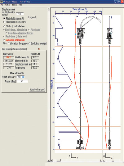 |
Fig. 1. Screen capture of Zeta Model.
|
|
For validation, Zeta Model results for natural vibration frequencies, buckling loads and bending stresses have been extensively validated with analytical calculation methods. Table 1 compares model results and an Euler buckling calculation for a straight vertical steel pipe, 50-ft long, 4-in. OD and 3-in. ID. Note that buckling loads (Pcr) from the model are almost identical to Euler results for a weightless pipe. However, when pipe weight is included, estimated buckling load limit provided by the Euler calculation is overstated by as much as 19%.
| |
TABLE 1. Critical buckling load modeling comparisons |
|
| |
End condition |
Euler
K factor |
Euler
Pcr,
lb |
Zeta Pcr
|
Difference
w/o gravity
% |
|
| |
w/gravity,
lb |
w/o gravity,
lb |
|
| |
|
|
| |
Fixed-Free |
2.0 |
1,766 |
1,469 |
1,748 |
1.0 |
|
| |
Fixed-Fixed |
0.5 |
28,261 |
27,795 |
28,261 |
0.0 |
|
| |
Fixed-Hinge |
0.7 |
14,455 |
14,130 |
14,453 |
0.0 |
|
| |
Hinge-Hinge |
1.0 |
7,065 |
6,566 |
7,063 |
0.0 |
|
|
Zeta Model validation efforts also encompassed dynamic modeling results. The dynamic calculations were validated by comparing first-mode natural frequency of the same vertical pipe discussed above, calculated using analytical equations, and the model; results are shown in Table 2. The analytical equations consider the mass of the pipe for dynamic purposes, but not the influence of gravity on the pipe. The model agrees very well with the analytical results without gravity, which is a basic Euler calculation assumption.
| |
TABLE 2. Critical frequency modeling comparisons |
|
| |
End condition |
Analytical
frequency,
sec–1 |
Zeta frequency
|
Difference
w/o gravity
% |
|
w/gravity,
sec–1 |
w/o gravity,
sec–1 |
| |
|
|
| |
Fixed-Free |
0.394 |
0.361 |
0.399 |
–1.4 |
|
| |
Fixed-Fixed |
2.516 |
2.469 |
2.500 |
0.6 |
|
| |
Fixed-Hinge |
1.722 |
1.695 |
1.724 |
–0.1 |
|
| |
Hinge-Hinge |
1.096 |
1.064 |
1.099 |
–0.2 |
|
|
The Zeta FEA Model allows modeling of a complex structure with unlimited supports, guy wires (or chains), and applied loads and applied moments to be defined by the user. Loading in the guy wires varies as the wires are stretched, and the load disappears if the guy wire goes slack. The user can force the stack to have specific displacements in cases where misalignment occurs. Wellhead and platform movements defined using sinusoidal, periodic motion can provide a simple “figure 8” movement pattern or a more complex pattern. The wellhead and platform can move independently of each other.
THE ZETA GAUGE
For enabling technology, attempts have been made in the past to build a gauge to measure axial force and bending of a lubricator section. However, due to the thick lubricator walls, conventional strain gauge technology was not accurate enough to provide the strain measurements needed. Fiber-optic extrinsic Fabry-Perot cavity interferometer type strain gauges were found, which would provide the needed accuracy for strain measurements. The fiber-optic measurement is based on light returned from the gauge. These gauges, shown in Figs. 2 and 3, have resolutions in the +/- 1µÎ range. Typical strain gauges without costly and specialized instrumentation normally have resolutions in the +/- 100 µÎ range.
 |
Fig. 2. Schematic of fiber-optic strain gauge operation.
|
|
 |
Fig. 3. Detailed view of fiber-optic strain gauge measurement.
|
|
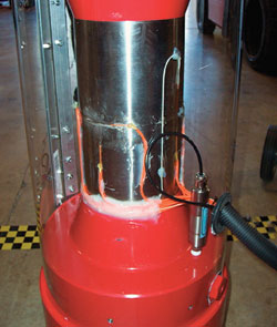
The Zeta Gauge is a section of lubricator or riser instrumented with a series of fiber-optic strain, pressure and temperature gauges around its perimeter. Fig. 4 illustrates a 4-1/16-in. gauge, outfitted with a clear outer covering for demonstration purposes. The gauge consists of a 2-ft long, 10,000-psi lubricator section with studded API flanges. Other gauge sizes can be constructed as needed.
 |
|
|
The gauge contains: three axial strain gauges at a 90° spacing around the lubricator, one temperature gauge, and one internal pressure gauge. The cable attached to the gauge in the well intervention stack contains six fibers that transmit only light. There is no electricity at the gauge. Back in the control cabin (or other safe area), several micro-processors are used to convert the light signal delivered by the Zeta Gauge cable to the required strain, temperature and pressure readings. Another micro-processor converts strain, temperature and pressure readings to axial force, bending moment, and bending direction outputs.
FIELD RESULTS
The Zeta Safety System has been exercised in real-time mode on several well intervention operations to ensure the system is robust and further validate its measurements, Fig. 5. Results from these field applications were extremely encouraging. The system provided accurate data with no operational difficulties during multiple days of operation. It was also confirmed that gauge calibration is stable. Results from this early work indicate that the required gauge calibration frequency may be on the order of once every 6 to 12 months.
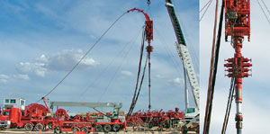 |
Fig. 5. Zeta System on a field operation.
|
|
The fiber optic strain gauges utilized in the system were expected to provide detailed measurements of stress-level changes in the well-intervention stack; and a quick review of actual field job measurements confirm this. Fig. 6 contains a plot of the measured axial force (in this case coiled tubing weight) and bending moment recorded by the system. The “Z” bending moment is the loading applied in the left/ right directions, as if you were in the coiled tubing unit control cabin and looking directly at the wellhead. The “Y” bending moment is the loading applied in the plane connecting the coiled tubing unit and wellhead (perpendicular to the Z bending moment direction).
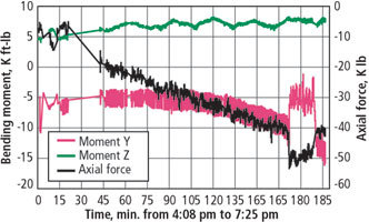 |
Fig. 6. Zeta Gauge measurements during a field operation.
|
|
Note the sinusoidal nature of the Z bending moment, with a frequency of about 20 min. This bending moment in the Z axis is actually the fleet angle of the coiled tubing as it is spooled off the reel, from one side to the other and back again. This small change in the direction of a force being applied to the intervention stack was measured by the system.
The Y bending moment that was recorded provides further evidence of the system’s ability to measure small changes in stack stress. During the run-in-hole period for the operation (from about 45 min. until 175 min. on the time scale), the Y bending moment measurement has 3 K ft-lb oscillation imparted on it – illustrated by the sharp, vertical spikes on this line. This is a result of the normal surging action on the coiled tubing reel motor, as most hydraulic motors exhibit some amount of surge and do not maintain an absolute constant rpm. This imparted a small, but constantly changing load on the top of the intervention stack.
The fact that the system was able to detect and measure both of these small changes in stack loads provides insight regarding its capabilities. Stack stress levels can be impacted by changing surface, downhole and floating offshore platform/ wellhead movement. One can easily envision how these real-time Zeta measurements could be used to determine when operations should be suspended if maximum stack stresses are approaching unsafe limits. Alternatively, real-time measurements from the Zeta Gauge could be used to direct the adjustment of a gimble table device, and confirm that stack stress levels are within acceptable limits following table adjustment.
A USER’S PERSPECTIVE
There are several potential applications of the system that BP views will be of value for well servicing operations. Wellhead movement on floating platforms can be measured for a variety of operating conditions to help understand possible load extent when intervention risers are used. The Zeta Model is an ideal tool for pre-job planning using estimated loads, to determine safety margin and sensitivity of various load parameters. However, as with all calculated estimates, it is important to determine how they represent actual conditions.
This tool should also provide insight to the way operational parameters can affect the system. Riser configuration and support from crane or motion compensator devices can be evaluated for a variety of conditions including wellhead movement, system pressure and tension/ compression from crane or compensator. The ability to incorporate real-time data for comparison to pre-job planning and design is a vital part of operational success to understand the nature of a problem. Once a true understanding has been achieved, there is always a way to manage its impact on value to operations.
SUMMARY AND FUTURE PLANS
The new Zeta Safety System is being successfully used in the field and is delivering economic benefits. Several conclusions can be drawn from the Zeta modeling and field work:
Pre-job modeling can enable cost-effective and safe equipment selection, tailored to the specific well intervention operation being planned.
Conventional approaches to intervention stack design (Euler calculations) have significant shortcomings and may overestimate buckling loads.
Dynamic modeling results are critical when designing well intervention stacks with moving wellheads and/or floating structures.
The worst case bending scenario may occur under zero load conditions.
Addition of stack supports can increase stack bending failure risk.
Real-time measurements from the system can be used to monitor stack stress, enabling fact-based operational decisions.
Zeta is helping the industry move away from the potentially risky practice of using the same well intervention stack equipment that was routinely used in the past, toward a comprehensive stack design process tailored to specific challenges of the planned intervention.
As intervention stack operations continue to migrate into more difficult operating arenas, we no longer have to guess if a titanium lubricator section is required for safe operations, or if a particular stack design has an adequate safety margin for the planned operation. This system can provide answers to these questions, and actual stack stresses can be monitored in real time when necessary.
While the current Zeta system is a dramatic leap forward in stack design and monitoring, it was not originally designed to model subsea interventions. As a result of recent industry interest, the model is being enhanced to include subsea riser modeling capabilities. This enhancement will include the ability to model pipe or wireline stress and displacement during a riserless subsea intervention. Loadings from varying ocean currents and movements of the floating structure are being incorporated into the available modeling scenarios. In addition, the concept of utilizing the Zeta Gauge for subsea riser stress monitoring applications is also under review. 
ACKNOWLEDGMENT
The authors wish to thank BP for its strong support and funding of this work. They are also grateful for the guidance and insight provided by Rodney Stephens, Charlie Michel and Walter Crow at BP, as the project has benefited significantly as a result of their contributions.
THE AUTHORS
|
 |
Ken Newman is founder and president of CTES, L.P., an engineering services company affiliated with Varco International. He holds a masters degree in mechanical engineering from MIT. He is a registered professional engineer in Texas and has been an SPE member since 1990. As a recognized authority on coiled tubing, Mr. Newman has authored several technical papers, magazine articles and patents. CTES provides modeling software, data acquisition systems, cable installation systems and specialized sensors to the coiled tubing industries, plus modeling products to wireline/ drilling industries.
|
 |
Ed Smalley, presently VP marketing & business development for CTES, L.P., an engineering services company affiliate of Varco International, holds a BS degree in engineering from Kansas State University. He is responsible for commercialization of new hardware and software products for coiled tubing, wireline and jointed pipe intervention. His more than 24 years’ of oilfield experience, starting with Schlumberger, includes new product development, field operations, sales/ management. After Schlumberger, he was Director, E&P business development with the Gas Technology Institute, where he managed launch of more than 60 new E&P products over eleven years. Mr. Smalley is a member of SPE, ICoTA and SPWLA.
|
| |
|
|

