Surface BOP with mudline shut-off device: A deepwater well construction alternative
Deepwater Drilling TechnologySurface BOP with mudline shut-off device: A deepwater well construction alternativeDesign and application of industry’s first mudline shut-off system to make surface BOP drilling environmentally safer with the accompanying high-pressure riser.Described here is the background of deepwater drilling using a BOP stack on the surface, rather than the previous conventional application of the BOP at the mudline, and the design and first application of a shut-off device located at the bottom of the riser to make the surface BOP system environmentally safe in the event of riser failure. The application is based on Total’s experience in its Donggala deepwater block in Indonesia in 2003. The shut-off device called the Environmental Safe Guard (ESG) was developed by Total and Cameron, with contribution of a riser design study by 2H Offshore Engineering. The deepwater rig used for the described case history ESG application was supplied and upgraded by Transocean. This successful application was the first time, worldwide, that a combination surface BOP with a mudline shut-off device was successfully run in 2,000-m water. INTRODUCTION In recent years, operators have been drilling wells in ever increasing water depths. These deepwater wells are drilled under specific conditions, namely a combination of extreme thermodynamic conditions (low temperature and high external pressure at mudline level) and a narrow margin between pore pressure and fracturing pressure. These conditions lead to a number of drilling difficulties, especially in terms of well control. Traditionally, these challenging wells are drilled using a subsea BOP stack connected at the mudline with a low-pressure riser to surface. From a well-control point of view, this configuration presents several limitations: BOP closing time may be long enough to allow part of the influx to migrate inside the riser; long kill and choke lines add significant friction losses which sometimes jeopardize kick control; and BOP components are subject to extreme thermodynamic conditions and, therefore, are prone to frequent failures which drastically increase rig non productive time (NPT). To overcome the drawbacks of using a subsea BOP stack and reduce costs associated with an expensive rig package, industry developed a technique using the BOP stack on surface in a “jack-up type” configuration and a high-pressure drilling riser. Primarily used in the Far East, this technique presents certain limitations, the main one being absence of a secondary barrier at, or just below, the mudline in case of riser failure. Total considered using this technique in 2,000-m (6,560-ft) water on its Donggala deepwater block, in Indonesia, offshore Mahakam Strait, Kalimantan Timur. A quantitative risk assessment (QRA) on surface BOP stack drilling was performed. This highlighted the necessity to have a shut-off device at mudline level to reduce the environmental impact in the event of riser failure. Total, in association with Cameron, designed and developed this subsea shut-off device (hereafter referred to as ESG for Environmental Safe Guard) and, with Transocean, upgraded a rig to allow safe and efficient drilling on Donggala. This article outlines development of the ESG in parallel with the required riser design and well architecture, as an alternative to deepwater well construction. An operational feedback on the successful running of the ESG is provided. SURFACE BOP BACKGROUND Over the past several years, industry has developed a technique allowing deepwater wells to be drilled with a semisubmersible rig with the BOP located at surface. Drilling with a surface BOP stack presents several advantages compared with traditional subsea drilling, such as:
Having acquired the deepwater Donggala block in 2001, Total’s objective for using the surface BOP stack technique in 2,000-m water was not only to drill its prospect in Indonesia in a cost-effective manner, but also to assess possible use of the technique in other subsidiaries worldwide. A quantitative risk assessment (QRA) on Donggala was conducted to evaluate potential risks of using surface BOP techniques in this specific case, and propose workable solutions to drill safely with this method. QRA ON SURFACE BOP STACK OPERATIONS A previous risk assessment study had been performed for a Total West African development using a surface stack, which concluded in an unacceptable risk level. This study was taken one step farther, incorporating the local East Kalimantan conditions and the specific project parameters. For the Donggala block, it was considered that a combination of the following events was sufficient for a blowout to occur: 1) drilling in an over-pressured reservoir, and 2) riser failure due to fatigue of induced by mooring failure, and/or 3) errant ship collision with the rig. A frequency of occurrence was attributed to each event, and the probability of a blowout to occur was calculated for the following conditions: 1) drilling with subsea BOP (SSBOP) stack; 2) drilling with surface BOP (SBOP) stack; and 3) drilling with SBOP with a subsea shut-off device at the mudline, i.e., an ESG. Blowout probabilities for SSBOPs and SBOPs were determined as being of the same order of magnitude. However, when considering the consequences of a blowout in terms of release to the environment, the SBOP was always greater than the subsea case. This is due to the fact that the major cause for blowout in SBOP configuration compared with SSBOP is considered as the riser failure. Once the riser has failed, access to the well is compromised and, therefore, no well killing operation is likely other than a relief well. A relief well being the only option, the uncontrolled flow of effluent from the well will last longer. One other key consideration was the mobilization time for a rig to be able to drill a relief well in the SSBOP case. The QRA clearly highlighted two specific points necessary to reduce environmental risk in the event of a riser failure. First, a strong foundation was required at the mudline that would facilitate riser failure above the mudline. Second, a form of subsea shut-off device was necessary at the mudline. Incidentally, its use allows a convenient re-entry – for instance, by disconnection of the failed riser, if proved necessary. Fig. 1 displays the probability matrix for higher fatigue failure and illustrates the QRA conclusions.
ESG DESIGN AND DEVELOPMENT Following the conclusions of the QRA, and in the perspective of drilling on the Donggala block using the surface BOP stack configuration, Total, in association with Cameron, designed and developed the ESG, Fig. 2, comprising, from bottom to top:
The primary decision to select the 18-3/4-in. equipment was based on:
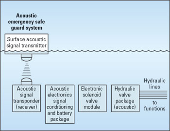
A summary of the riser design is presented later. The objective of the foundation was to strengthen the section of the well just below the mudline with the view that, in the event of a riser failure, this would occur above the mudline and facilitate a re-entry. The control system, unlike traditional subsea BOPs, was simplified to be operated in an acoustic electro/ hydraulic manner (for the main emergency functions) with an ROV control panel as a backup, Fig. 3.
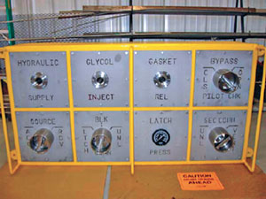
It should be stressed that, from the beginning, the ESG is not designed for traditional well-control situations and was not to be considered a BOP. It is designed to seal the well and disconnect the riser from the seafloor if required. By doing so, it allows a safe, temporary well abandonment in case of emergency, and the possibility to re-enter the well at a later stage. The acoustic control system was provided by Simrad and comprised surface and subsea portions. The surface portion comprised one rack mounted transceiver and a touch-screen panel located on the rig floor connected to a hull-mounted transducer. In addition to the fixed components, a portable topside unit connected to a dunking transducer was also provided to allow remote control of the ESG from a pre-selected location. For the subsea portion, two subsea transducers were located on opposite sides of the ESG, and a subsea control unit (SCU) was connected to Cameron’s acoustic valve package. Redundancy was provided in both surface and subsea systems up to the SCU. In parallel with the ESG manufacturing, two other key operations were required. The selected rig had to be upgraded to enable ESG running, and the ROV had to be able to operate all functions on the ROV panel, Fig. 4. Seven functions were added to the ROV manipulator to perform requested tasks. And a high-pressure pump was installed to allow local charging of the accumulator banks or manipulation of the ESG components by hot stab at the seabed.
Despite the several parties involved and several problems, mainly due to interfaces, the ESG was successfully commissioned in time for the drilling campaign. RISER DESIGN AND MONITORING To date, for surface BOP drilling, a 13-3/8-in. casing riser complete with specially designed fatigue-enhanced premium connections has been used. The impact of the ESG at the mudline, the foundation and the need for a riser buoy, to provide sufficient surface tension, had to be determined. 2H Offshore Engineering was contracted to perform a riser design study to assess global riser behavior and evaluate need for additional components to cope with increased bending loads. To perform the study and use real environmental data (waves, currents, etc.) an oceano-meteo survey was performed on the Donggala block with data retrieved every two months. Riser design calculations highlighted the magnitude of the loads and the need for stress joints. The design and manufacture of these stress joints included additional operational considerations into their final manufacture. The ability to repair and re-thread after use determined that adapter spools would be required and the following components were designed (see also Fig. 5):
Finally, with the above elements, the following load cases were considered as giving the most extreme riser load conditions:
It was found that, to satisfy the design requirements, the following conditions should be fulfilled:
To monitor, in real time, riser behavior during drilling, a dedicated riser management system was installed, comprising the following elements:
To summarize the riser design calculations and provide effective guidelines for offshore personnel, some operating envelopes have been established both for riser installation and drilling conditions with riser connected, Fig. 6.
DRILLING RIG AND WELL ARCHITECTURE For the Donggala campaign, it was decided to select a rig with surface BOP stack drilling experience. However, the selected rig had to be upgraded to be able to run the ESG features:
These modifications were carried out in parallel with ESG fabrication and commissioning. The use of 13-3/8-in. riser (against 21-in. riser for traditional subsea drilling) limits the number of available casing strings. Therefore, the risk exists not to be able to reach the geological objective should a casing string, for instance, be set higher than expected. Donggala specific objectives and geology highlighted this, and the well design included certain contingencies, including use of expandable casing. The Well OTI-1 drilled on the Donggala block was designed with two contingency expandables, as shown in Fig. 7.
CASE HISTORY: DRILLING OTI-1 WELL The well was the first ever drilled, worldwide, in surface BOP mode with a subsea shut-off device at the mudline. It was also the first exploration well on Donggala block. The well was successfully drilled and evaluated, with the following main highlights. A strong foundation was obtained below the mudline by successful jetting of the 30-in. conductor pipe. Despite unexpected drilling difficulties (shallow water flow, well kick, heavy mud losses), the well was drilled successfully. Due to one casing string set higher than expected, an expandable casing string was run and successfully expanded, returning the well to original hole size. Running of the ESG was smooth, proving that the specific procedure was operationally viable. On bottom, pressure on the lower connector had to be increased only once during all operations. The adjustment was made without difficulty using the appropriate ROV tool kit. And the riser management system was used in real time during drilling, and the rig position was modified to cope with the criteria defined by the riser analysis. As far as ESG and associated equipment are concerned, some problems occurred (mainly due to the “infancy” of the system):
All these misfunctions have been identified and solutions are addressed for a future use of the ESG. Overall, the well is considered a major technical success, leading to new perspectives in surface BOP stack drilling, both for exploration and development wells. CONCLUSIONS For the first time, worldwide, a combination of surface BOP stack coupled with a shut-off device at mudline level has been run to successfully drill a deepwater well. For a newly developed device, running and operating the ESG in 2,000-m water is considered a major technical success. Presence of the ESG at the seabed allows safe drilling of deepwater challenging wells with a surface BOP stack configuration. As it is designed, the ESG is rig interchangeable and is available for use by other operators in any part of the world. This field-proven device, in association with some emerging technologies such as expandable casing, aims at radically changing our traditional conception of deepwater well architecture and will allow such wells to be drilled in a safe and cost-effective manner.
|
|||||||||||||||||||||||||||||||||


- Advancing offshore decarbonization through electrification of FPSOs (March 2024)
- Subsea technology- Corrosion monitoring: From failure to success (February 2024)
- Driving MPD adoption with performance-enhancing technologies (January 2024)
- Digital transformation: A breakthrough year for digitalization in the offshore sector (January 2024)
- Offshore technology: Platform design: Is the next generation of offshore platforms changing offshore energy? (December 2023)
- 2024: A policy crossroads for American offshore energy (December 2023)

