Seafloor Exploration
New vessel expands deepwater geotechnical capabilities
The latest-generation geotechnical drillship can conduct detailed site investigations in water depths as great as 3,000 m. It has proven itself in a variety of locations.
W. Scott Rainey, President, Fugro McClelland Marine Geosciences, Inc., Houston
A new breed of geotechnical vessel, built and converted in Singapore in 2001, has established a track record as a viable platform for a full suite of tools. Since it was christened, the vessel has set a new geotechnical water depth record of 8,300 ft. In addition to Gulf of Mexico (GOM) projects, the vessel has completed major investigations offshore Mexico and California. Current backlog for this vessel includes a major program in Brazil and a joint industry program (JIP) associated with the investigation of gas hydrate deposits in the GOM.
SITE INVESTIGATION HISTORY
The first US offshore lease sale occurred in 1945, with the first platform installed nine miles off the Louisiana coast in 1947. Two years later, 44 exploratory wells had been drilled in the GOM. Greer and McClelland, Inc., conducted the first marine geotechnical investigation of an offshore structure in 1947 for Chevron, using a land-based drilling rig placed on a temporary platform. This approach quickly became outdated with increasing water depths.
In the 1960s, the working platform changed from a barge to a vessel equipped with a marine drilling system and four-point mooring to improve efficiency. For conventional work on the shelf, this is still the preferred mode today. The first deepwater GOM investigation was done for Shell’s Cognac platform in 1,000 ft of water in 1977. Initially, most studies were conducted using exploration drilling rigs. From 1985 to 1995, specialized North Sea geotechnical vessels were available during the winter off-season, but depths were limited to about 6,500 ft.
In 1995, the work volume and increasing water depths mandated that a deepwater vessel be positioned in the GOM. Together with Cal-Dive, Fugro outfitted the Uncle John with a suitable drilling system. As the oil and gas industry ventured into deeper and deeper water depths, there grew a pressing need to meet the challenge by developing a vessel capable of detailed site investigations for prospective developments in up to 3,000 m of water. By 2000-2001, it became clear that global market conditions would support a new generation of deepwater geotechnical ships, so Fugro invested in a new vessel. Christened in 2002, the vessel has conducted 14 deepwater investigations, in water depths as great as 8,000 ft.
VESSEL SELECTION
Deepwater geotechnical vessels are scaled-down versions of petroleum drillships without well control equipment. General traits include about 260 ft in length, dynamically positioned, motion-compensated and capable of drilling to 10,000 ft. The vessel includes all ancillary equipment and a large moonpool. Equipment of this size and capability is not readily available, and must be designed and fabricated specifically for the geotechnical market.
By early 2001, it was clear that a new-build was not commercially viable. A conversion was the only economic alternative. The company needed an acceptable hull between 240 and 260 ft long; the remaining vessel attributes were not important, considering the conversion’s magnitude. Eventually, a decision was made to go forward with the Western Magellan, purchased from Western Geophysical.
The ship was modified in Singapore in 2000 and completed field trials, but it never entered service. Concurrent with the conversion, National Oilwell in Houston was contracted to design and manufacture a drilling system specifically for this vessel. Major conversion items included relocation of the heliport to the bow; installation of a moonpool; installation of the thruster and dynamic positioning system; fabrication and installation of a 12-m (39-ft) extension plug incorporating the mud system to lengthen the vessel; installation of deepwater winches and four-point mooring system; fabrication and installation of a motion-compensated drilling system; and installation of a pipe-handling system.
Renamed the Fugro Explorer, the vessel departed Singapore in late May 2002. Deck equipment was installed in Galveston by mid-July, and it was completed in August, Fig. 1.
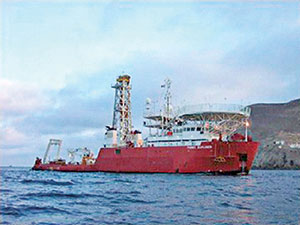 |
Fig. 1. Pictured offshore Baja California, Mexico, the Fugro Explorer has set water depth records while conducting geotechnical investigations since going into service in 2002.
|
|
VESSEL CAPABILITIES
Station keeping during a site investigation is achieved with a Kongs-berg/ Simrad DPII System. The system integrates position reference systems (DGPS, taut wire and USBL) with three, 800-hp tunnel thrusters and the main propulsion. The benefit is the ability to weathervane during operations, which increases the working weather window.
Drilling system. The drilling system comprises five major components: drilling derrick, power swivel, motion compensation system, pipe-handling equipment and mud system. The 90-ft derrick (80-ft clearance) has static and dynamic load capacities of 180 t and 150 t, respectively. An active traveling block-type compensator (15-ft stroke) is used for heave compensation.
Drilling power is from a 400-hp, hydraulically operated, top drive power swivel that can produce 23,000 ft-lb of torque and maximum rotational speed of 250 rpm. The power swivel has a 4-in. open spindle and an equally sized hydraulic valve at the top, which allows deployment of downhole tools or samplers without breaking the drillstring.
A unique feature incorporated into the top drive is a collet elevator, a system of hydraulically operated gripping jaws encased below the power swivel. The collet provides 150-t lifting capacity, allows make-up or breakout of the tool joints, and rotates 90° from the vertical to facilitate drill pipe handling. This greatly enhances drill pipe lowering and raising speed, as the collet replaces elevators, links and power thongs, and helps raise or lower pipe in a controlled mode.
Pipe handling. The pipe handling system integrates the collet, pipe feeder, pipe crane and pipe racks, Fig. 2. The crane rests on a track system that enables it to move across the vessel’s width in a controlled mode, even in severe weather. The crane has a double clamping device that grabs the pipe, picks it up and delivers each joint to the pipe feeder. Once made up, the string is lowered, and another joint is added. Drill pipe can be run at 400 ft/hr.
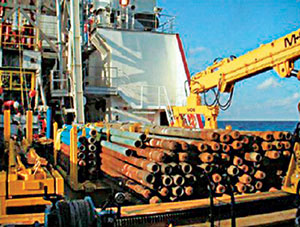 |
Fig. 2. The vessel’s pipe handling system integrates four components and can run drill pipe at a rate of 400 ft/hr.
|
|
Mud system. National Oilwell applied its Smart Mud Instrumentation and Controls (SMIC) System to be the central data acquisition and control for drilling materials and fluid systems. The SMIC is a computer system that allows all mud components to be controlled or monitored from a central (onboard or remote) location, or from the driller’s cabin.
The onboard system helps the driller control and monitor bulk powder silos, liquid mud tanks, active mixing pits, mud mixing pumps, surge tanks, hoppers, and transfer and drilling pumps, using a graphical display on a computer screen. The driller can also monitor each tank volume, observe the mixing process, and control mud usage during drilling.
Drilling fluids are critical to collecting quality undisturbed samples and making accurate soil property measurements. Geotechnical drilling is done without a riser and recirculation system, with drilling fluids expulsed at the seafloor. Drilling fluid volume used for this is about 1.5 to 2 bbl/ft. The vessel has four bulk silos (6,050 total cu ft), two liquid tanks (620 total bbl), and three active mixing pits (525 total bbl).
DEEPWATER SITE INVESTIGATIONS
Deepwater facilities can be anchored using either piles or suction caissons. Each option dictates the equipment used for the site investigation. Pile-supported foundations are typically installed to deeper depths (down to 500 ft). This mandates a deeper drilling, sampling and downhole in situ testing program. Suction caissons are for shallower embedment depths (~150 ft), and require continuous soil profiles, obtained with a combination of seabed testing equipment (which pushes various probes into the soil), and shallow drilling and sampling. Both field data collection types are available.
Offshore geotechnical site investigations use motion-compensated rotary drilling methods, mud system, seabed frame and various samplers or downhole tools for measuring foundation properties. A typical site investigation requires a combination of drilling, sampling and in situ testing.
For drilling, the power swivel advances the drill pipe to the depth required, the hole is cleaned using fluids, and tools or samplers are deployed. Samples or tests are conducted almost continuously for the top surficial sediments and at larger intervals at deeper depths. All of the downhole tools or samples are deployed and retrieved using wireline techniques.
The seabed frame, 10-t deadweight and a base of 10 sq ft, is equipped with a hydraulic clamping mechanism for specialized testing. It is deployed to the seabed using two 35-t motion-compensated traction winches. Constant tension hydraulic cylinders with a 15-ft stroke are used to compensate for any vessel motions. The seabed frame can also deploy various seabed testing sensors or probes.
Lab testing is done onboard, concurrent with drilling, in a 1,200-sq ft lab. Tests included moisture content, unit weight, and shear strength measurements to evaluate the soils’ pertinent index and engineering properties.
Dolphin Tools are designed specifically for deepwater application and include downhole mud thruster, sensors and remote memory system without the need of an umbilical. Some sensors are also interchangeable system components. Tools used for deepwater investigations include a cone penetrometer, remote vane, piezoprobe and hydraulic-fracture packer system. Each of these tests has a special application relating to foundation investigation.
During deployment, the Dolphin Tool is simply dropped through the drill pipe annulus, where it latches into the BHA. For pushing a sample or conducting the cone penetration test, the seabed frame is hydraulically clamped to the drill pipe, to immobilize the drillstring during testing. Mud pressure is increased inside the annulus, to force the tool into the soil at a uniform ROP over the test’s length.
The local memory unit collects all test-associated data. The tool is retrieved back to the vessel’s deck, and data are downloaded to a computer for later processing. Drilling is advanced, and this process is repeated until all downhole sampling and in situ testing is completed to the boring’s termination depth.
Downhole Dolphin remote vane tests are performed in soil borings at predetermined depth intervals, to measure the soils’ in situ shear strengths. The tool has a four-bladed vane that is inserted into the soil and rotated with an electric motor. The degree of rotation and torque are recorded in a remote memory unit (RMU). After test completion, data are retrieved at the surface. The soil’s undrained shear strength is then computed from maximum vane blade torque and transducer calibration factors.
Piezoprobe dissipation tests can be performed in the soil borings at predetermined depths, to measure the soils’ excess pore pressure and pore pressure dissipation. Piezoprobe tests are performed using a wireline-operated, small-diameter piezoprobe.
Wheeldrive Seacalf. The Wheeldrive Seacalf (3.4 m x 3.4 m) applies the seabed frame used for continuous cone penetration testing. The seabed unit consists of a grooved wheel-thrust device, cone rods, sensors, seabed controls, surface controls and a data acquisition system. The sensor is attached to the cone rods and positioned into the seabed frame’s center between the wheel thrust units.
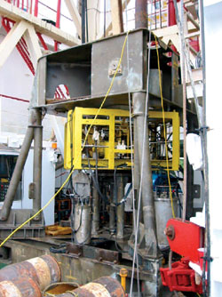 |
Fig. 3. Wheeldrive CPT system on deck, prior to deployment.
|
|
Once on bottom, the system is activated, and the four grooved wheels grip the test rods, rotate and produce the thrust required to advance the sensor into the soil. The rods are all pre-strung, and they penetrate the soil at 2 cm/sec, so tests are relatively quick.
As the cone penetrometer penetrates into the seafloor, cone resistance, sleeve friction and pore pressure are all recorded continuously. Data are transmitted to the surface using a multi-conductor umbilical, and results are displayed graphically on the computer. This tool’s big benefit is that it provides a continuous profile over the boring depth.
Halibut seabed vane. The Fugro Halibut seabed remote-vane system measures in situ shear strength of the near-seafloor, soft cohesive soils in the immediate vicinity of the soil borings. This system’s remote vane tool is supported by a square base plate (5 ft x 5 ft), called the Halibut basket. It is lowered to the seafloor over the drilling vessel’s stern, rather than through the drill pipe, using a wireline.
The company also operates a third-generation variant called the Halibut 3, which automatically acquires data at a number of depths without retrieval to the surface for resetting the test depth. Once the vane penetrates to the required depth, recording of test data begins after the torque on the vane blade, driven by an electric motor, exceeds a preprogrammed torque threshold. Data are sampled once every second and stored temporarily in the vane tool’s RMU, until they are retrieved at surface.
CASE STUDY 1
In early 2004, Kerr-McGee Corp. announced the development of its Constitution field (Green Canyon Block 680), about 190 mi southwest of New Orleans in roughly 5,000 ft of water. This field will be developed with a truss spar similar to the Nansen, Boomvang and Gunnison spars, with a processing capacity of 70,000 bopd and 200 MMcfgd. First production from the Constitution spar is expected in mid-2006.
In 2003, feasibility studies were performed using geophysical data and generalized soil conditions to evaluate the facility’s preferred foundation type. The recommended scheme included nine 84-in diameter piles driven to 213-ft penetration, grouped three to a cluster, with three clusters spaced nearly equally around the truss spar hull.
The mooring system comprises a large anchor chain connected to the anchor pile, and about 6,500 ft of 4.75-in diameter wire rope, followed by another anchor chain that attaches directly to the spar hull through fairleads.
The Fugro Explorer was mobilized in Galveston, Texas, last April, when it was configured in drilling mode. Based on the foundation geometry, the field investigation included one deep boring at the center of each anchor cluster, extending to 300 ft below mudline. Three soil borings were drilled to penetrations ranging from 270 to 300 ft BML, to explore the subsurface stratigraphy and obtain soil samples for lab testing. Soil sampling, lab and in situ tests were performed.
Downhole Dolphin remote vane tests and Piezoprobe dissipation tests were performed in the soil borings to measure the soils’ in situ properties. The downhole vane tests were concurrent with drilling and sampling. Typically, a vane test was conducted adjacent to a soil sample for comparison. The Halibut remote vane system was used to measure in situ shear strengths of the near-seafloor cohesive soils.
The final lab testing was completed onshore. A final engineering report summarized the field investigation, offshore and onshore lab testing, and associated tests. Detailed geotechnical engineering for the foundation piles was also done. At present, the team is working on an integrated study to look at combining all available site information from the investigations, and performing a slope stability assessment for the near-surface soils encountered over the site.
“The Fugro team has supported Kerr-McGee in the geotechnical investigations for all six of their existing and planned deepwater spar facilities,” said Mike Beattie, Kerr-McGee’s Constitution project manager. “Fugro has consistently provided superior technical performance and equipment, enabling Kerr-McGee to complete its foundation designs. The geotechnical staff brings solid experience and industry recognition to the table when design challenges arise. The addition of the Fugro Explorer vessel to the list of company-controlled equipment further enhances the ability of Fugro to complete the full geotechnical program.”
CASE STUDY 2
Independence Hub is a unique, multi-operator development that involves participation by Anadarko Petroleum; Dominion Exploration & Production, Kerr-McGee Oil & Gas, Spinnaker Exploration and Devon Energy. This group of companies recently agreed to jointly develop natural gas and condensate output from six gas fields in the Atwater Valley, DeSoto Canyon and Lloyd Ridge areas of the deepwater Gulf of Mexico.
The hub will be located in Mississippi Canyon Block 920 and owned by Enterprise Products. Water depths range from about 8,000 to 9,200 ft. The structure will be a semi-submersible moored by 12 suction piles. Four clusters will have three suction piles, each.
Fugro has been involved with the project since early 2004, providing preliminary integrated engineering-geologic reports and foundation design reports based on re-interpretation of client-provided 3D seismic data. Based on that study’s results, a much more comprehensive study was proposed, using geophysical and geotechnical techniques. The geophysical investigation, to be carried out by Fugro GeoServices Inc., will involve the collection of Deeptow or AUV data over the site. Results of this study will ultimately be integrated with results of the geotechnical investigation completed by FMMG.
In August 2004, the company was contracted by GulfTerra Field Services, LLC (fully owned subsidiary of Enterprise), to perform the final geotechnical investigation, spanning Mississippi Canyon Blocks 876, 919, 920, 921 and 964. The Fugro Explorer was selected as the only alternative for acquiring both samples and in situ data in this range of water depths, Fig. 4.
|
Fig. 4. The vessel’s unique blend of capabilities was deemed the only alternative for a Kerr-McGee-operated project in the GOM’s Mississippi Canyon area.
|
|
The field program was completed between Oct. 6 and Oct. 30, 2004. It consisted of 10 seabed piezocone penetration tests (PCPT’s), two soil borings, and two series of near-seafloor, Halibut in situ remote vane tests. Seabed PCPT’s were performed to a maximum depth of about 134 ft, using the Seacalf Wheeldrive system.
The requirement for the vessel to operate in both drilling and seabed PCPT modes necessitated a change-out between the systems at sea, a process typically undertaken in 8 hr or so. The Halibut in situ remote vane shear tests were performed between 2- and 28-ft penetrations in the immediate vicinity of the soil boring locations. The two soil borings were performed to a penetration depth of 115 and 150 ft BML, respectively. Soil sampling intervals were specified, based on interpretation of the geophysical data and platform foundation requirements. Soil sampling and downhole in situ remote vane tests were performed using Dolphin tools.
The investigation’s primary purpose was to develop foundation design recommendations. Results will be integrated with geotech data once all geophysical data become available to provide the final, design-level integrated site characterization report. Once a reliable model has been established for the site, the company will provide input to the client and installation contractor for design of suction piles, riser touchdown point and pipelines.
“FMMG has provided a unique level of expertise in the characterization of this deepwater development that few companies could provide,” said Independence Hub project manager Jim Guion. “Their conscientious analytical approach has allowed GulfTerra to maximize data collection for the development while minimizing the acquisition cost – an invaluable combination for deepwater developers.”
CASE STUDY 3
Several petroleum and service companies, as part of a JIP, initiated a multi-year research and technology program to better understand the characteristics and behavior of hydrates, and their impact on E&P in the GOM. This JIP is led by ChevronTexaco and funded by industry and the US Dept. of Energy. The objective is to develop technology and data, and to assist in the characterization of naturally occurring hydrates in the deepwater GOM.
The two-year, overall project schedule has been divided into two phases. Pressing issues in Phase 1 include:
- Develop a research and technology plan to characterize hydrates
- Assess and understand potential hazards to E&P in these sediments
- Plan and execute a drilling, sampling and testing program to characterize sediments
- Develop a hydrate database.
The Fugro Explorer has been awarded the Phase 1 portion related to drilling, sampling and testing in GOM methane hydrate sediments. The work scope includes drilling six boreholes in two deepwater areas, Keathley Canyon and Atwater Valley. Boreholes will be drilled and sampled up to 2,000 ft below mudline in water depths down to 4,300 ft. Field work will occur in 2005.
Various workshops are being held to define the entire process of drilling, sampling, testing, handling and preserving hydrate samples. Specialized expertise is required, because the hydrate sampling tools developed over the past few years have had limited field testing. In addition to the vessel and drilling systems, the company will provide its own specialized sampling systems, including the hydraulic piston sampler and the corer. 
THE AUTHORS
|
 |
Scott Rainey is president of Fugro McClelland Marine Geosciences and a registered PE. He joined Fugro as a senior geo-technical engineer in 1981 and was promoted to president in 1994. After receiving an MSCE degree from The University of Texas at Arlington in 1978, Mr. Rainey began compiling extensive international experience as a project manager for geotechnical projects in China, Japan, Southeast Asia, Australia, the Mediterranean and the Middle East. He is currently responsible for all Fugro marine geotechnical activities in North America, Central America and South America.
|
| |
|
|

