Underbalanced Drilling
DDV usage reduces time to round-trip drill string, cuts costs
Installation of a downhole deployment valve program at various sites worldwide has allowed continued UBD operations that otherwise would have required flaring, flowing or snubbing operations
Brian Grayson, Weatherford
Fluid invasion of a reservoir during conventional overbalanced drilling techniques can cause considerable formation damage. Increased awareness of the degree of damage possible has raised interest in the benefits that underbalanced drilling (UBD) offers. UBD techniques are not necessarily suitable for all reservoirs, but they can provide significant benefits in such instances as:
- Depleted reservoirs, where infill wells can be drilled with little or no damage.
- Highly permeable, fractured reservoirs, where fluid invasion can be substantially limited, and consequent degradation of permeability reduced or eliminated.
- Hard formations, where penetration rates can be increased greatly.
In spite of their many benefits, UBD techniques can have their disadvantages, such as higher associated costs, and increased, perceived risk and safety issues. Perhaps the most significant risk arises during normal tripping of the drill string to change the bottomhole assembly (BHA). During UBD operations, the formation is allowed to flow; so a surface pressure is ever present in the annulus. A rotating control head is used to control the pressure. As tripping begins, and the pipe is stripped through the wellhead, the pressure must be managed to prevent a pipe-light situation.
Killing the well is one method of controlling it, and this allows for conventional tripping of the drill string into and out of the well. However, in some situations (such as the one described in these case histories), killing the well is not an option. The potential for significant fluid loss and formation damage is too high, or the costs of these risks cannot be determined.
Until recently, snubbing was the only accepted method for tripping drill string in a constant underbalanced state. Subbing removes the possibility of damaging the formation but increases tripping times, adding appreciable operational expense. If multiple drillstring trips become necessary, overall costs can escalate rapidly. In addition, the snubbing unit cannot seal around complex assemblies, such as conventional sand screens or expandable sand screens (ESSs).
To address these problems, the Downhole Deployment Valve (DDV) has been used successfully in 20 installations worldwide, some of them retrievable and others permanent. Examples include three 7-in. (26 lb/ft) and one 9-5/8-in. (47 lb/ft) sites in Quebec, Canada; a four-well trial program in Oman's Nimr field; and two 7-in., 26-lb/ft DDVs in successive gas wells in Louisiana. In all cases, usage of the device reduced tripping time considerably while maintaining UBD conditions. Operators realized substantial cost-savings, as opposed to traditional snubbing methods. Maximum setting depth, shut-in pressure and setting deviation in these installations have been 4,536 ft, 1,770 psi and 27° in open hole, respectively.
CONCEPT AND DESIGN
In its ongoing efforts to improve and refine UBD techniques, Weatherford has made significant progress toward development of the DDV. This full-opening, downhole isolation valve (DIV) is hydraulically operated from the surface, similarly to a subsurface safety valve. However, the DDV is not a substitute for a subsurface safety valve.
The DDV is placed, in the open position, as an integral part of the intermediate casing string, below the well's deepest, potential pipe-light depth. Drill pipe is tripped and subsequently stripped out under pressure, until the BHA reaches a point directly above the DDV. The DDV is then closed by applying hydraulic pressure from the surface and encapsulated in a control-line bundle in the annulus, between the casing and surface pipe. Wellhead pressure is bled to zero.
When isolation of the well is observed, the balance of the pipe is pulled from the hole, as for a dead well. The new BHA is installed, and drill pipe is rerun to a depth directly above the DDV, where a pipe-heavy condition exists. Pressure is applied to the well to equalize with the pressure trapped below the DDV. When these pressures are equal, hydraulic pressure is applied, through the control-line bundle, to open the DDV. Drill pipe can then be run to bottom and drilling recommenced.
The control-line bundle consists of two, 1/4-in. stainless- steel tubulars, and a single, 5/16-in. braided cable that is placed between the tubulars, Fig. 1. Application of pressure to the first line opens the valve, while such application to the second line closes the valve. If the DDV is equipped with downhole sensors, a mono- conductor braided wireline can replace the braided cable. Downhole sensors placed in the DDV transmit an electrical signal to the surface, allowing measurement and reading of real-time downhole pressures and valve position from the surface.
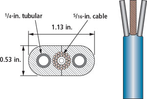 |
Fig. 1. Control line bundle.
|
|
The DDV can be placed in either of the following conditions:
- Permanent installation. The DDV is cemented in place in the casing string, becoming a permanent part of that string.
- Temporary installation. As occurred in Oman, the DDV can be run as part of the tie-back string for a liner, which is cemented to a point below the proposed DDV setting depth. This allows recovery of the DDV at the end of drilling operations.
A wellhead penetration system is typically required to facilitate communication of the control line fluid from a surface control unit to the control line.
The basic features of the DDV are illustrated in Fig. 2:
- The full-opening ID is equal to, or greater than, the drift diameter of the casing on which the DDV is mounted. For example, a 6.276-in. ID valve for 7-in., 26-lb/ft casing.
- The outside diameter (OD) is less than the drift diameter of the surface casing. For example, an 8.5-in. OD valve for running in 9-5/8-in. ID, 47-lb/ft casing.
- The valve seal features a curved flapper with a metal-to-metal sealing seat and a maximum, differential operating pressure rating of 5,000 psi.
- The body is also rated at 5,000 psi of differential pressure (internal and external).
- A dual, tubular control line, run from the valve to surface, hydraulically opens and closes the valve. Maintaining hydraulic pressure holds the valve in either position.
- Standard P-110 casing grade- equivalent construction.
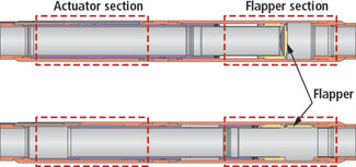 |
Fig. 2. Downhole Deployment Valve (DDV) operation. The top view shows the DDV in the closed position. The bottom view shows the actuated mandrel and the DDV in the open position.
|
|
QUEBEC, CANADA OPERATIONS
In the Beekmantown formation, an operator in Quebec, Canada was set to drill a dual lateral, gas storage well. Hole size was 6-1/8 in. The well schematic is shown in Fig. 3. The main goal was to drill this well using UBD technology to mitigate formation damage caused by solids and liquid invasion of the reservoir. The reservoir characteristics would thus be in an optimum condition for the injection and production of storage gas.
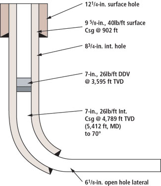 |
Fig. 3. Well design diagram of Canadian, horizontal underbalanced well with DDV installed permanently with 7-in., 26-lb/ft intermediate casing.
|
|
Operational objectives included:
- Increased safety during underbalanced operations.
- Allowance for safe, efficient tripping of drilling assemblies.
- Drilling a well to TD and completing it without injuring personnel or incurring lost time.
- Drilling to TD and completing while maintaining UBD conditions.
- Minimize rig time and cost associated with traditional snubbing in and out of hole during UBD.
- Use inner string cementing operations to cement a 7-in. casing string and DDV.
- Eliminate the need to kill the well during tripping.
- Eliminate gas flaring during trips.
The 7-in., 26-lb/ft DDV was set at 3,595 ft, in 8-3/4 -in. open hole at a 19° deviation. The DDV was then cemented in place with a 7-in. casing string. Subsequently, over a 21-day period, a total of 5,117 ft of 6-1/8-in. hole was drilled through the DDV. During installation of casing and the control line bundle, time averaged 2 min. or less per joint of casing. In addition, trouble- free wellhead penetration was conducted, using a special, modified casing head and mandrel hanger.
The valve was used by the operator to successfully shut in the well for 12 drill string trips. It allowed for subsequent underbalanced installation of a tubing completion string. Accordingly, the operator's tripping procedure times were reduced by an average 13 hr per trip. This created cost savings of about C$450,000 (US$331,000) when compared against the cost of using a snubbing unit to trip.
NIMR FIELD, OMAN
A successful four-well program was recently completed for operator Petroleum Development Oman (PDO) at Nimr field in Oman. The FK 167 location accesses the Al-Khalata/ Amin formation, with typical TVDs of 3,035 ft. Average BHP is 1,090 psi.
The program had a number of objectives, one of which was to install the DDV and be able to function-test it in the open and closed positions from a surface panel. In addition, the operator wanted to hold pressure from below the DDV on the backside of the flapper valve. On one or more of the wells, the operator and vendor planned to tie in the DDV control line to a Cameron wellhead penetration system. They also planned to re-run the DDV control line for the first time.
Results generated were in line with expectations. On the second installation, the control line was re-run into the hole, together with protector clamps. Furthermore, the DDV functioned in open/ closed position on each occasion, as designed, and it held pressure from below the flapper valve. After this particular installation, the DDV was redressed and made ready for future use on the next wellsite location. As planned, the DDV was also installed with the wellhead penetration system, Fig. 4. This allowed the control line interface to be connected from the deployment valve through the wellhead, to the surface control unit without the need to break and re-test the BOP stack.
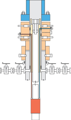 |
Fig. 4. At the top of the wellhead, the penetration system allows the control line interface to be connected from the deployment valve through the wellhead to the surface control unit. The DDV control lines are color- coded red for closing and blue for opening.
|
|
LOUISIANA GAS WELLS
In northern Louisiana, Pinnacle Operating Co. installed two DDVs in successive gas wells in the James Lime Trend. The wells had TVDs of 5,800 and 6,4000 ft, with 6-1/8-in. hole sizes and 3,400-psi pore pressures. In addition to saving money through reduced tripping times, the operator hoped improved the well's production rates by preventing formation damage. The company also wanted to allow for a method to conduct workovers at a later date while maintaining underbalanced well conditions.
Over a two-month period, two 7-in., 26-lb/ft DDVs were installed in the wells. They were set at depths of 2,589 and 2,416 ft, in 8-3/4-in. open hole. In one well, 6,809 ft of 6-1/8-in. hole were drilled through the DDV in six days. At the second well, 10,750 ft of 6-1/8-in. hole were drilled through the DDV in 11 days. Trouble-free wellhead penetration was achieved by using a special, modified casinghead and mandrel hanger.
The DDVs successfully isolated formation pressure for two required drill string trips in one well, and three trips in the other well. They also allowed for subsequent underbalanced installation of tubing completion strings. Maximum shut-in pressure was 1,500 psi. Total time for opening procedures was 5 min., and closing procedures averaged 10 min. Actual time to open and close the valves was less than 1 min.
- By utilizing the DDVs, the operator reduced tripping times by an average 7.75 hr. This equates to a reduction of 45% to 52%. During installation of the casing and control line, average duration per joint of casing was between 2.5 and 3.0 min. This is highly favorable, compared to the alternative of killing the wells with heavyweight fluid.
PERFORMANCE SUMMARY
Since November 2001, there have been 20 installations of the valve, and much has been learned. The technology has proven to be extremely useful and reliable, in the drilling and completion environment. A summary of the track record is shown below:
| |
Number of installations : 20 |
|
|
Retrievable: 8 |
|
|
Permanent: 12 |
|
Maximum setting depth: 12,800 ft, MD |
|
Maximum shut-in pressure: 2,650 psi |
|
Maximum number of wells shut-in under pressure: 12 |
|
Maximum setting deviation: 27° in open hole, 68° cased hole |
|
Number of oil wells : 5 |
|
Number of gas wells : 15 |
|
Maximum amount of hole drilled: 19,200 ft of 6-1/8-in. hole over a 14-day period. |
|
Regions run : North America, Middle East, Asia Pacific, North Sea |
This successful track record has proven that the DDV concept is reliable and durable. The technology increases the options available to the operator for both drilling and completion. It also opens up opportunities for equipment utilization and installation methods that were not previously feasible.
FUTURE DEVELOPMENTS
Some future wells will require a higher DDV pressure rating. A 10,000-psi-rated valve is in the final development phases and will be ready by mid-2004. Some wells may require wire-wrapped screens for sand control. Currently, wells are either choked back to sub-sand production levels or are allowed to produce sand that is handled at surface. In both cases, sand production either incurs the added expense of increased maintenance or reduces output. The DDV will allow introduction of sand screens to a well while an underbalanced state is maintained in the reservoir.
The ultimate objective is to run a DDV and then introduce an ESS. ESS allows for optimal production rates that exceed what is achievable using gravel pack technology. But due to the configuration of the ESS installation, it cannot be performed underbalanced without a DIV. The combined UBD/ESS completion is expected to optimize production levels – the UBD ensures that the reservoir is undamaged and the ESS provides a high-rate, sand-free production conduit. The combination of technologies should ensure maximum hydrocarbon recovery at the highest rate.
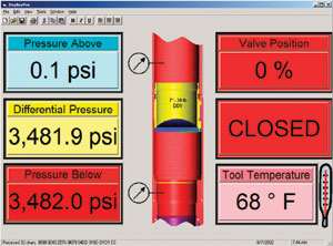
An instrumented DDV is nearing completion of development. This next-generation DDV will provide a surface readout that shows pressure (above and below the closed flapper), downhole temperature and actual flapper position, Fig 5. 
 |
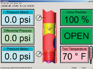 |
Fig. 5. In future installations, a software interface will display the differential pressure and show that the DDV is in either closed or open position.
|
|
THE AUTHOR
|
| |
Brian Grayson is manager, Global Product Service Line, for Weatherford International's Underbalanced Systems. He began his career in R&D Engineering, where he held various engineering positions within Weatherford. In December 1998, Mr. Grayson began developing the DDV concept. Following the tool's development, he moved to an operations position to create application systems for the DDV's operation in June 2001. He holds a BS degree in aerospace engineering from Texas A&M University.
|
| |
|
|

