Intelligent Well Technology
Intelligent well system succeeds offshore West Africa
A simple, reliable intelligent well system installed offshore West Africa is succeeding because of correct technology selection, as well as diligent planning and installation
Jesse J. Constantine, Intelligent Completion Business Unit, Weatherford International, Houston
For more than 10 years, a growing number of oilfield operators have begun recognizing the value potential of intelligent wells. This increasing acceptance stems from the development of intelligent well technology that can address some of the initial fundamental adoption barriers and user perceptions. Those barriers were cost, reliability and integrated functionality.
The growing pains experienced by suppliers and users of intelligent wells now prove to have been worthwhile. Adoption of intelligent well technology is spreading globally, and utilization is growing steadily. The key to overcoming these growing pains has proven to lie in two areas:
- Correct technology selection and development
- Operational excellence in planning and installation.
A completion installed recently for a major operator illustrates how both of these factors must be present for a successful installation. This article discusses the challenges faced, the benefits delivered and lessons learned in deployment of a simple, reliable intelligent completion system offshore West Africa.
SYSTEM REQUIREMENTS
The operator's four objectives were to complete a well from an unmanned satellite platform, independently control production from three zones, acquire production allocation data for each zone, and deliver this data to a central control location. Control actuation of the well, along with data acquisition and storage, would be managed from a Floating Production, Storage and Offloading (FPSO) vessel approximately 3.5 km (2.2 mi) away. The intelligent well system requirements included:
- Independent zonal production flow control
- Pressure and temperature data acquisition from each zone
- Single-string, multi-zone completion
- Single-trip completion installation with accurate depth correlation
- Completion to straddle 7-in. liner hanger system, set in 9 5/8-in. production casing
- Simple completion pulling at end of well life
- Scaleable control system architecture
- Operation from remote FPSO location via subsea umbilical
- Minimized requirement for wellhead penetrations.
The challenge, however, was to reliably and safely accomplish all of this in less than six months' lead time, and within a tightly constrained budget.
SYSTEM SELECTION
The operator cited a number of reasons why a combined optical/ hydraulic technology platform made the best sense for their application:
- Proactive and positive approach to providing the best technical solution to the well's high deviation and contingency, event management needs
- Simple cost-effective system with sound, “staircase” approach to new technology introduction
- Single-trip installation with minimum intervention during completion running
- Simple wellhead interface
- Timely delivery schedule
- Scaleable, surface data acquisition system
- Minimal contingency intervention tool requirement
- Simple chemical cut/shift to release completion pulling at end of well life.
The technology platforms used are simple hydraulic flow controls, and high reliability and sensitivity optical sensors. Both were chosen for their suitability to spawn simple, modular intelligent well systems displaying high reliability at an acceptable cost. This helped the operator successfully balance the risk/ benefit equations to comfortably justify a commitment to an intelligent well installation. In committing to this system, the operator expected the following benefits:
- No intervention required for manipulation of in-well flow controls
- Real-time well tests performed on selected zones
- Reaction time for remediation to problems nearly instantaneous
- No production loss associated with flow control manipulation
- Health, safety and environmental risks eliminated, as no personnel are required on the platform to manipulate in-well flow controls or acquire data.
IMPLEMENTING THE SYSTEM
Fundamental to making this installation a success was the application of detailed engineering rigor to system design and operational planning.
Application engineering. An important step in achieving the client's objectives was undertaking detailed application engineering prior to installation. This engineering effort ensured that components were environmentally compatible with the reservoir conditions, and could be assembled and properly deployed while interfacing with the casing and liner already installed. This effort included conducting a tubing stress analysis, confirming material compatibility, pressure and temperature ratings, geometric eccentricities, control line routing, cross-coupling clamp placement, sub-assembly makeup, and internal and external drifting prior to the manufacturing process.
Installation planning. It has been noted that problems during installation have contributed to many intelligent well and permanent monitoring system failures. A great deal of effort was applied to achieve operational excellence in this installation. In addition to thorough application engineering, installation procedures were equally critical to successful deployment. Developing these procedures included such considerations as identifying where surface components – including spooling units and sheaves, a temporary portable hydraulic unit and fiber optic installation unit – would be placed during completion equipment deployment.
One of the most valuable techniques applied was undertaking two exercises, “Complete the Well On Paper” (CWOP) and “Hazard Identification” (HAZID). All stakeholders in the system participated in these exercises and rehearsed the procedures, step by step, to identify issues involved with system deployment. Communication at this stage between all stakeholders, both clients and suppliers, identified critical contingencies that could be applied during event sequence problems or equipment failure.
SYSTEM COMPONENTS
The in-well system has two core components – hydraulic flow control and optical sensors. At surface, two independent systems are also required, one for optical data acquisition and one to actuate the hydraulic flow controls.
Flow control. The in-well flow control system had to operate the three zones independently without intervention. With-in each zone, a Remotely Operated Sliding Sleeve (ROSS™) would be selectively actuated from surface. The ROSS is a simple, hydraulic on/off sleeve using metal-to-metal and non-elastomeric sealing technology to assure reliability. Sleeve movement is achieved by using a balanced hydraulic piston. The requirement to install three ROSS sleeves resulted in the number of hydraulic control lines to surface being in excess of the available wellhead penetrations. This was overcome easily by including a Hydraulically Controlled Addressing Unit (HCAU) immediately below the upper 9 5/8-in. production packer, Fig. 1.
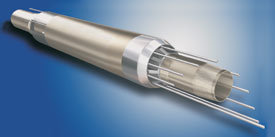 |
Fig. 1. The Hydraulic Control Addressing Unit (HCAU) enables operation of multiple Remotely Operated Sliding Sleeves (ROSS) with just two hydraulic lines to surface.
|
|
This HCAU reduced the number of hydraulic lines from the surface while allowing independent operation of the three zonal valves. The HCAU is a simple switching control that requires only two hydraulic lines from the surface to operate up to four valves below it. This means that only two hydraulic lines have to be run from the tubing hanger to the first producing zone, ensuring that there are sufficient wellhead penetrations for all the hydraulic and optical lines required.
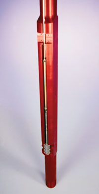 |
Fig. 2. This optical P/T gauge mounted on a mandrel is representative of a set deployed in a recent offshore West Africa application.
|
|
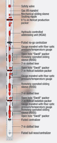 |
Fig. 3. This combination, multi-zone hydraulic control/ optical sensing intelligent well system was installed recently offshore West Africa.
|
|
From this point down, two hydraulic lines were run to each producing zone's ROSS. This well architecture also results in a reduction in costs associated with control line supply and rig time to install.
Optical sensors. The requirement to acquire reservoir parameters was addressed by including a permanent pressure and temperature (P/T) gauge at each production zone, Fig. 2. Optical P/T gauges were selected, because they have a significantly reduced component count when compared to the electronic equivalent. They also have no moving parts. Both factors are beneficial as regards long-term reliability and stability.
The optical P/T system had minimal impact on the completion architecture. A gauge mandrel was run above the ROSS in each zone to mount the low-profile optical sensor. A single, optical cable bundle facilitated interrogation of the gauges. At the surface, an optical wellhead outlet ported the cable through the wellhead to a reservoir monitoring system (RMS).
Optical surface data acquisition system. The RMS houses the opto-electronics that interrogate the in-well P/T gauges. This unit is on the unmanned satellite platform. It contains an optical source that transmits light via the in-well cable to the P/T sensors. An optical signal is reflected from the sensors, along the same in-well cable, back to the RMS system, Fig. 3.
The system measures this reflected signal's wavelength. An onboard computer then converts this wavelength into the output measurement parameters of pressure and temperature. Changes in reflected wavelength then equate to changes in measurement parameter.
The permanent monitoring data generated by the RMS on the unmanned platform are communicated to the FPSO via an Ethernet link. Here, the data are stored in archives for future reservoir analysis. A monitor is also located on the FPSO to display real-time temperature and pressure data from the three producing zones. The monitor connects to the unmanned satellite through the same Ethernet communication umbilical and modems used by the hydraulic controls.
Hydraulic surface control system. The hydraulic switching unit and sliding sleeves are controlled from the FPSO via an Operator Interface Controller (OIC). This is a touchscreen monitor that communicates with a processor on the unmanned platform containing the system's logic software. Signals between the OIC and processor are communicated to and from the unmanned platform via the Ethernet umbilical connection.
Inputs to the OIC control a Hydraulic Power Unit (HPU) on the unmanned platform. The HPU contains the solenoid valves, pumps, accumulator, fluid filtration, hydraulic oil reservoirs, and required electronics to operate the hydraulic supply system for the in-well flow controls. Sensors included in the HPU provide feedback to the FPSO operator, including information on such HPU events as low fluid levels, equipment tampering, manual HPU operation and successful in-well tool actuation.
SYSTEM INSTALLATION
A site integration test (SIT) was conducted with the client to ensure that all finished system components correctly interfaced with each other, and with external systems. This was performed successfully as part of a final functional system check prior to shipping to the well site.
Careful consideration was given to the sub-assembly rationale, to ensure ease of handling in transit and unloading at the rig floor, as well as minimizing rig time to install. The completion design from the well's toe to the tubing hanger was broken down into 15 subassemblies, Table 1.
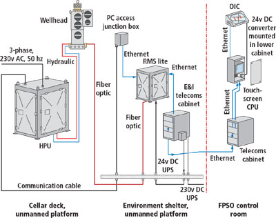 |
Fig. 4. This Simply Intelligent™ completion system was installed on an unmanned platform and controlled from a remote FPSO.
|
|
| |
Table 1. Intelligent completion system sub-assembly breakdown |
|
| |
No. |
|
Sub-assembly components |
|
Function |
|
|
|
|
| |
1 |
|
Fluted centralizer
Bull nose/ bull plug |
|
Ensure ease of entry into the 7-in. line top |
|
| |
2 |
|
Fluted centralizer above four
3 1/2-in. x 20-ft blast joints |
|
Protect and centralize the string as it enters and drifts the 7-in. liner |
|
| |
3 |
|
ROSS™
Gauge mandrel
HellCat2™ isolation packer
Splice sub |
|
Flow control and data acquisition of deepest producing zone |
|
| |
4 |
|
Several blast joints |
|
Placed across lower producing interval |
|
| |
5 |
|
Orientation sub |
|
Facilitate alignment of assembly #6 with the control lines running from the spooling units |
|
| |
6 |
|
ROSS™
Gauge mandrel
Splice sub
HellCat2™ isolation packer
Splice sub |
|
Flow control and data acquisition of middle producing zone |
|
| |
7 |
|
Several blast joints |
|
Placed across middle producing interval |
|
| |
8 |
|
Orientation sub |
|
Facilitate alignment of assembly #9 with the control lines running from the spooling units |
|
| |
9 |
|
ROSS™
Gauge mandrel |
|
Flow control and data acquisition of upper producing zone |
|
| |
10 |
|
Orientation sub
Fluted no-go centralizer |
|
Facilitate alignment of assembly #11 with the control lines running from the spooling units
No-go sub tagged the 7-in. liner to assure accurate space-out of equipment |
|
| |
11 |
|
HCAU
Locator sub
Splice sub
95/8-in. HellCat2™ production packer
Splice Sub |
|
HCAU allows only two hydraulic lines to be run to surface |
|
| |
12 |
|
Landing nipple
Mechanical sliding sleeve |
|
Displacement of well to initiate production |
|
| |
13 |
|
Gas lift mandrel |
|
Preferred artificial lift method |
|
| |
14 |
|
TRSCSSV |
|
Production safety valve |
|
| |
15 |
|
Tubing hanger |
|
Wellhead interface and hydraulic control and optical line porting |
|
|
In total, five days were spent running the completion, from picking up the first subassembly until reaching the tubing hanger. This was achieved despite some additional time being taken for hydraulic control line termination and testing, and for fiber optic cable connection and testing. This time was well within planned estimates.
One operational issue did result in some unplanned rig time. During the space-out procedure, a dogleg immediately above the 7-in. liner resulted in the no-go sub hanging up. This had been recognized as a possible event, but the string's location at hang-up was exactly where the completion was due to be set. After careful deliberation, it was agreed that contingency action, should this event occur, was to set the packers, and then “stretch” the tubing to allow hanger installation. This was successfully performed, and the tubing hanger landed.
Installation of the surface equipment for the hydraulic controls and optical data acquisition system was accomplished successfully. During commissioning of these systems, it was requested that the HPU's electronics section be relocated. The electronics were repositioned on the platform's top deck, away from a Zone 2 work area. This was accomplished by co-locating the HPU electronics with the optical sensing RMS system.
During initial well test operations, relocation of the HPU electronics had yet to be completed. However, by using a temporary hydraulic control panel that forms part of the installation equipment, well test operations were completed successfully. These well tests were the final step in confirming the intelligent well system's operation, and that the installation was a success.
LESSONS LEARNED
There were no major “train wrecks” encountered during this installation. The primary lesson learned was that by applying rigorous equipment design, application engineering and operational execution planning, a combined hydraulic flow control, optical-sensing intelligent well system can be installed correctly the first time, safely, and within budget.
Good communication between all system stakeholders was a critical success factor. Up-front system requirements, interface definitions, well environments, delivery requirements, tool functionality and control architecture were agreed, thoroughly documented and understood by all. In addition, performing the CWOP and HAZID exercises proved invaluable. This step minimized the potential for show-stopping events and ensured that contingencies were ready and on stand-by.
The client was present at the various Factory Acceptance Tests (FATs) performed after equipment manufacture. This facilitated ownership and familiarity by all stakeholders. Performing the SIT gave final confirmation of system readiness prior to offshore mobilization.
CONCLUSIONS
This installation's success demonstrates that, although intelligent well systems may appear complex and somewhat daunting, a successful installation and reliable operation can be achieved. One simply needs the right equipment, and a well-thought-out completion design and installation plan. Selecting simple, reliable, fit-for-purpose completion equipment, coupled with the right combination of system design, application engineering and operational excellence, has proved that intelligent wells have become a viable completion option. 
THE AUTHOR
|
 |
Since joining Weatherford in July 2002, Jesse J. Constantine has been product line manager for Hydraulic Remote Flow Control Systems in the company's Intelligent Completion Business Unit. Mr. Constantine has 17 years of experience in the oil and gas industry, covering a wide range of product management, engineering, applications and business development. Specifically, he has devoted the last five years of his career to working on intelligent completions.
|
| |
|
|

