Exploration Technology
Valhall life of field seismic: Permanent, on-demand 4D – a new era begins
Considerable benefits are hoped for in what can only be termed the boldest commitment to 4D seismic yet
Perry A. Fischer, Editor
Valhall field is at once the best and the worst place to carry out a grand experiment in time-lapse seismic. It is the best place because of its complexity, which can only be broached by the very best in seismic imaging technology. But that same complexity also makes it one of the worst places to try the world's first, serious attempt at permanent 4D seismic on demand. The reservoir is undergoing considerable subsidence, and an upcoming waterflood project may dissolve, harden, fracture, solidify and otherwise have unpredictable effects on the reservoir's fragile chalk. Because a gas cloud all but prevents imaging with conventional seismic, multicomponent sensors become the only way to go, in what is easily a bold foray into the future by the Valhall partners. It's the remaining reserves – some 500,000 to 600,000 thousand remaining barrels of oil that is driving this effort, combined with the fact that only superior reservoir understanding and management will allow their economic recovery.
BACKGROUND
Valhall field is located in Blocks 2/8 and 2/11 in 70-m deep water, 290 km offshore Norway in the southwest corner of the Norwegian Sector of the Central North Sea, Fig 1. It was discovered in 1975 by Amoco and went into production in 1982. To date, the field has produced about 500 million bbl of oil from about 100 development wells and has at least 500 million bbl of remaining oil reserves. Another 30 or so wells will be drilled in the next three years. The reservoir, covering 50 sq km, is a northwest-southeast trending anticline formed during the Late Cretaceous, comprising the high-porosity, low-permeability chalk, of the Tor and Hod formations, and varying in thickness from 10m to 60 m. Production is primarily from the Tor, with the underlying Hod formation contributing about 8%.
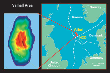 |
Fig. 1. Location of Valhall field.
|
|
Initially, development focused on the crest of the field. In 2002, a satellite plat-form was placed on the southern flank of the field to access reserves there, and an additional plat-form was just added to drain the north flank. A water injection platform will be installed this year for drilling water injection wells, Fig. 2.
 |
Fig. 2. Valhall schematic, showing well head platforms (WHP), water injection platform (WIP) and other structures.
|
|
The new platforms, development and waterflood wells require considerable planning, which in turn requires the use and integration of all available data. A 1992 seismic streamer survey was used for comparison with a high-quality, high-resolution 3D streamer survey shot in 2002. When these volumes were subtracted, the resulting 4D response was extremely robust and can be used to guide well placement on the structure's flanks. However, a large gas cloud of about 20 sq km severely degrades the seismic signal at the reservoir top, making structural interpretation and well planning extremely difficult with conventional streamer acquisition. To overcome this difficulty, it was recognized early on that multicomponent acquisition would be needed.
The easiest way to acquire the multicomponent data is through a conventional towed airgun, discharged at a sufficient offset to receivers so as to generate converted “C” waves at the reflector(s). These can be detected, along with compressional waves, at the sea floor using ocean bottom cable with multicomponent sensors. Following a rigorous study on the idea, one of the first 3D/4C datasets was acquired across the field in 1997 – '98 by Geco Prakla. Building on that successful survey, the installation of the world's first field-wide permanent ocean bottom cable array occurred in the summer of 2003. Dubbed Life of Field Seismic (LoFS), this system will not only provide improved structural reservoir imaging, but should also allow for improved monitoring of the waterflood, management of existing wells, and drilling of new injectors and producers. This will be an essential element in BP's goal of E-field implementation – that is, continuous reservoir monitoring and management – by 2005.
When discovered, Valhall field originally had 2.1 billion bbl oil in place, with about 250 million bbl recoverable. Further delineation and characterization of the reservoir now puts those numbers at 2.6 million bbl oil in place with 1.05 million bbl recoverable. Valhall has produced without supplemental pressure the last 20 years. Depletion and the resulting subsidence of the extremely high-porosity chalk (40 – 50%) added pressure support due to strong compaction of the weak chalk sediments. In addition, this subsidence has created wellbore stability problems that result in an average well life of only seven years. Subsidence has also affected surface facilities and has led to planning for a complete replacement of present facilities, which is scheduled for as early as 2007. A waterflood project was sanctioned in 2000, which is expected to recover an additional 182 million bbl. The reservoir is extensively faulted, making both well planning and water injection management a great challenge.
LoFS BENEFITS
There's no doubt that this project squarely puts BP and its partners in the forefront of pioneering 4D. Prior to this, the only meaningful permanent seafloor seismic system was the FARM experiment at Foinaven. That experiment was a muddled success. The system comprised hydrophones only. It had relatively sparse sensors and there was considerable attrition of the sensors over time. For the new system, there are several ways that the LoFS data should pay handsome returns.
Identifying structural complexity. The top reservoir is 2,500 m below the surface. Valhall has the almost all of its producers drilled in the crest of the structure. More than 40 of these wells have long horizontal sections, with multiple penetrations of both the top and base of the reservoir. This provides numerous control points for depth conversion and thickness estimates of seismic data. Due to the complex structure, seismic images are still critical in verifying well observations.
In light of these reservoir characteristics, fault identification becomes critical due to their potential impact on well placement and pathways for the upcoming waterflood. Coherency from conventional marine seismic streamer surveys can be processed to provide coherent events, revealing faults, even in the gas-cloud area. P-wave data is very poor in the obscured area.
C-waves yield a much improved image of the top reservoir reflector when compared to the conventional streamer seismic. In fact, beneath the reservoir top, within the gas-cloud obscured area, the only dataset (since mid-1999) that has been usable for well-planning work is the OBC converted wave data. Streamer data always has noise (unwanted signal) in the form of water-borne multiples from reverberations between the sea floor and the ocean surface. By having both hydrophones and geophones on the seabed, these can be easily eliminated.
Various processing schemes have been used by the major seismic contractors. PGS did the initial processing, using a conventional DMO-consistent, common-conversion point-binning scheme to map the reflection point prior to stack. This focused the effort to establishing a velocity field, consistent with the complex subsurface, directed to provide the optimal stacked image. Within BP, a processing effort aimed to produce images using a PSDM approach. CGG in 2000 and WesternGeco used algorithms that corrected shear-wave splitting to improve resolution. Both of these techniques used a DMO scheme for mapping into common image points. All of these have had their advantages.
PSDM appears to give the best overall image of the structure. Correcting for S-wave splitting has proven to enhance seismic resolution. Coherency processing, spectral decomposition and other techniques aimed at enhancing fault imprints are routinely used in evaluating the resulting stack volumes from P-wave and C-wave recordings. Recent drilling using these analyses has confirmed 60 – 70% of seismically identified faults greater than 10 m of throw.
Improved well planning/placement. There are several ways that the LoFS data should pay handsome returns through better well planning and placement at Valhall. Several types of drilling problems that occur at Valhall can be avoided. Near the crest, drilling beyond the reservoir will likely result in getting stuck, due to differential pressure between the depleted reservoir and undepleted rock. Encountering unmapped faults or perforating wells in or near faults can have profound negative effects. Also, the production value related to optimal well placement can be substantial. A 20% increase in production for one well can have an impact of more than $20 million.
There have been five dry wells to date at Valhall. If, as envisioned, another 55 wells are drilled during the next 25 years of field life, and the odds of a dry hole remain unchanged, one could expect two to three more dry holes. Wells at Valhall average $25 million, so if LoFS prevents two dry holes, the system would nearly pay for itself.
Finally, the feedback created by 4D means that as waterflooding proceeds, sweep efficiency can be enhanced.
Better 4D signal. A permanently installed OBC system, as opposed to a retrievable system, is better for 4D because merely picking up and redeploying a retrievable OBC creates false 4D signals. To the extent that an accurate 4D difference volume relies on repeatability, permanently installed 4C sensors provide the ultimate system – at least on the receiver side. As for the source, every effort will be made to accurately position the airguns to make each survey as repeatable as possible; but all variations caused by the sea and weather are impossible to eliminate, although some environmental factors are measured and recorded.
Better reservoir management. The 4D response from frequently repeated surveys can help plan injection rates and manage/ monitor performance of both producers and injectors. LoFS is expected to increase the field production profile, which now stands at 75,000 bopd, by 10,000 bopd. Precise monitoring of subsidence and the effect on seismic is now possible by comparing the 4D signal to known subsidence at a wellbore. The full potential of the technology is not yet known, but overall, it should result in 60 million bbl of additional recovered oil.
LoFS PROJECT SPECIFICS
| |
Table 1. For multiple surveys,
LoFS is more cost effective
than conventional seismic. |
|
| |
|
Net Present Cost
($ millions) |
|
| |
OBS |
$67.93 |
|
| |
Streamer |
$33.96 |
|
| |
LoFS Pilot |
$34.85 |
|
|
The permanent LoFS monitoring seismic system, costing US$50 million, was installed in the summer of 2003. Although expensive, when viewed on a NPV basis for multiple surveys, over time, LoFS is more cost effective than repeated conventional seismic surveys, Table 1. The project began with the installation of four large cylinders, installed 1-m deep in the sea floor by jetting out the material inside. Housed within these cylinders are seismic array terminals (SATs). An ROV was used to connect the individual seismic cables into the SATs, Fig. 3. During trenching of the seismic cables into the seabed, the sensors were kept live, allowing continuous communication and monitoring to ensure that no damage was done to the 4C system during installation. The network covers 40 sq km – about 70% of the reservoir – comprising some 120 km of seismic cables, containing 2,504 multicomponent sensors with a total of 10,016 channels.
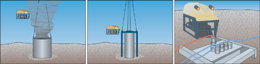 |
Fig. 3. Installation of seismic array: a) jetting in protection cylinders; b) inserting electronics into cylinders; c) ROV plugging cables into the SAT.
|
|
During seismic acquisition, a new type of airgun is fired from a standby vessel – the annular port airgun. The new source design is an annulus containing the air chamber and shuttle valve. These surround a hollow passage through which air supply hoses and electrical control cables are routed. Increased acoustic output per unit volume of air is due to increased surface area of the toroidal-shaped bubble (rather than spherical). This design eliminates gun plates, air manifolds, exposed air hoses and electrical cable jumpers. It protects fittings and connectors from the air blast, and results in less drag due to smaller sub-array profiles. These are important considerations, since a field vessel will tow the source arrays, taking two to three weeks and some 50,000 firings to complete one survey – and surveys are to be repeated every three months.
Continuous communication between the vessel and platform allows for real-time quality assurance of the signal. The data – comprising some 7 Terabytes – is much larger than most surveys. It is recorded at one of the platforms, and then transferred to shore via a fiber optic cable in close to real time. Six surveys are planned during the first 18 months. First data is now available to interpreters, and a second acquisition should be available soon. Experience from the Valhall installation is expected to inspire new development and help optimize installation and operations for even small and medium size fields.
PARTICIPANTS
As for the leaseholders, the Valhall partnership comprises BP Norge AS, operator, 28.1%; Amerada Hess Norge, 28.1%; A/S Norske Shell, 28.1%; and Total E&P Norge AS, 15.7%. Major contractors on the LoFS project include Bolt, for the new seismic source design; Facilium, project engineering, procurement and management; Fugro, vessel and source deployment; Concept Systems, navigation/ positioning for repeatability, QC control and certain data management elements; IO's Digicourse, digital source control system; OYO Geospace, maker of the OBS 4C system; PGS for processing; Rovde, vessel provider/ operator; Westland Geoprojects, source handling; and Subsea 7 for trenching/ installation of the cables and system. 
REFERENCES
Lewis, S. M., Barkved, O. and R. Kjelstadli, “Planning waterflood wells in a gas cloud: Optimizing the use of a 4C ocean bottom survey and setting the scene for a life of field seismic implementation in the Valhall field, Norwegian North Sea,” SEG International Exposition and 73 rd Annual Meeting, Dallas, Texas, October 26 – 31, 2003.
McCormack, N. J., Beacom, L., Mjelde P. C. and C. Richard, “The filling history of the Valhall field, Norway: Implications for future development,” AAPG Annual Convention, Salt Lake City, Utah, May 11 – 14, 2003.
Life of Field Seismic – World's First at Valhall, BP, CD Produced by www.ghostwriter.no, September 2003.
O. Barkved, K. Buer, K. B. Halleland, R. Kjelstadli, T. Kleppan and T. Kristiansen, “4D seismic response of primary production and waste injection at Valhall field,” EAGE 65th Conference & Exhibition, Stavanger, Norway, June 2 – 5, 2003.
|

