Casing While Drilling
Extending casing points in abnormal pressure using drill-in liners
How to use managed pressure liner drilling to reduce trouble time and allow drilling farther into narrow-margin wells
Bob Quitzau, Independent Consultant, and Colin Leach, Argonauta Drilling Services
Liner drilling systems have been used for penetrating high pressured formations into deeper depleted zones.1 – 4 This article presents a method for using liner drilling to extend casing points in environments where pressure gradients are increasing with depth. The practice should be considered an alternative for reducing trouble time and reaching objectives in critical, narrow-margin wells.
The concept relies on managing annular fluid pressure around the large-diameter liner to create favorable equivalent circulating density (ECD) profiles that allow penetrating farther into narrow pore pressure-fracture gradient windows. However, as liner drilling proceeds beyond normal limits, risks must be managed for making drilling connections, liner cementing and maintaining well control. The approach is consistent with ongoing industry focus on managed-pressure drilling using conventional drillstrings.
VARIABLE ANNULUS FLUID GRADIENTS
Historically, high mud weights and circulating friction pressure around a liner have been potential causes for lost circulation. However, if the liner is used for drilling into rising pressure gradients, the friction pressure and mud density can be engineered to reduce the risk of formation fracture.
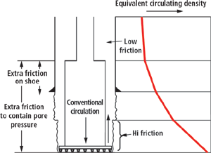
In this concept, the hole is drilled – with a conventional drillstring – to traditional well control limits, e.g., a kick tolerance limit. The drill-in liner is then run, mud weight is reduced and drilling continues. Circulating friction pressure around the liner raises ECD near the bottom of the hole. ECDs in the shallower hole sections are lower since the rate of friction loss around the small-diameter liner running string is less than that around the liner, Fig. 1. Increasing pore pressure gradients near the bit can be controlled, while protecting weaker shallower zones. The ECD profile can be managed within the pore pressure-fracture gradient window by adjusting static mud weight and circulating rate.
 |
Fig. 1. Variable fluid gradient for liner drilling.
|
|
In some circumstances, this concept may allow significant extra interval to be drilled beyond conventional limits, thus increasing the chances of reaching deeper objectives. Other benefits include reduced stuck pipe consequences and added capability to kill underground blowouts. The liner drilling process results in installation of full-strength tubulars in the well. Liner drilling may also be used prior to reaching conventional casing points to mitigate cyclic fluid losses and fluid gains (ballooning effects) that often plague narrow-margin drilling.
EXAMPLE LINER DRILLING CASES
Two example cases are described to illustrate the range of potential benefits: 1) drilling to the conventional casing point to reduce “ballooning” problems; and 2) extended liner drilling beyond the conventional casing point to increase casing setting depth. Risks connected with these example applications are discussed in a later section.
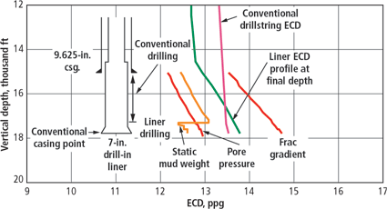
Case 1: Mitigation of ballooning. In the first example, liner drilling is used to reduce overall risk and trouble time by running the liner before reaching the traditional casing point. A conventional drillstring is used to drill to a depth 500 ft shallower than the expected liner setting depth. The liner is run to bottom and mud weight is reduced to compensate for added friction pressure around the liner. The liner then drills the remaining 500 ft to the planned pore pressure limit.
As shown in Fig. 2, ECD at the liner bit is sufficient to overcome the pore pressure, while ECD at the previous casing shoe is dramatically lower than the ECD created by a conventional drillstring. This is an example in which liner drilling can reduce risks of ballooning trouble while staying within industry well-control norms.
 |
Fig. 2. Drill-in liner ECD profile for mitigating ballooning problems.
|
|
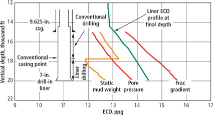
Case 2: Extended liner drilling. Fig. 3 shows a case for extended drilling with a 7-in. liner. The hole is first drilled with a conventional drillstring to 17,800 ft, where the liner would normally be set, based on a kick tolerance limit. The liner is then run and used to drill an additional 2,200 ft beyond the normal casing point.
 |
Fig. 3. Drill-in liner ECD profile for extended liner case. After conventionally drilling to 17,800 ft, an additional 2,200 ft can be drilled with a 7-in. liner.
|
|
When the liner is first run to bottom, static mud weight is reduced to 11.9 ppg from 13.1 ppg to ensure that the ECD profile falls within the pore pressure-fracture gradient window. As drilling progresses, mud weight and flowrate are adjusted frequently to maintain acceptable ECD profiles, as well geometry, pore pressure and temperature change.
This job is designed with a flowrate of 475 gpm and mud weights ranging from 11.9 ppg at start of the job, to 12.7 ppg at 20,000 ft. Minimum annular velocity below the mudline is 91 ft/min. to ensure adequate hole cleaning. The bit face is adequately cleaned by maintaining bit hydraulic horsepower above 3.0 hp/in2 throughout the drilled interval. The maximum pump pressure is 3,750 psi.
Further study indicates that favorable ECD profiles for the 7-in. liner would allow drilling much deeper than shown in this example, though equipment reliability issues may preclude such an opportunity. This case demonstrates that liner drilling has the potential to significantly extend casing points – if the risks can be managed.
Large diameter liners. Liner sizes greater than 7-in. may also present drilling opportunities, though some limitations increase as liner diameter increases. Table 1 lists job planning parameters for a range of liner sizes for environments similar to the two cases above. The results should not be extrapolated to any other conditions. The complexity of liner drilling requires evaluation of each application to identify benefits and risks.
| |
Table 1. Job planning parameters |
|
| |
Liner OD,
in. |
Footage
drilled |
Depth
reached |
Flowrate,
gpm |
Pump
press., psi |
Pump hp |
|
|
|
|
| |
16 |
550 |
10,000 |
1,200 |
2,800 |
1,975 |
|
| |
13 3/8 |
550 |
11,500 |
850 |
3,000 |
1,500 |
|
| |
9 5/8 |
1,000 |
16,000 |
570 |
3,800 |
1,275 |
|
| |
7 |
2,200 |
20,000 |
475 |
3,750 |
1,050 |
|
|
In general, larger liner sizes require higher pump power to generate friction, and satisfy all operating constraints. The need for pump redundancy and contingency planning becomes more of a challenge for these cases. Use of liner bit sizes that are smaller than normal increases the capability to add friction to the bottom of the hole. This provides added flexibility to shape the ECD profiles to drill longer intervals with larger liner sizes.
LINER SYSTEM DESIGN CONSIDERATIONS
Liner assembly and drilling parameters that can be varied to optimize a liner drilling plan are shown in Table 2.
| |
Table 2. Liner drilling design parameters |
|
| |
Liner assembly |
Liner drilling |
|
|
|
|
| |
Drillable interval |
Static mud density |
|
| |
Final liner overlap length |
Circulation rate |
|
| |
Liner bit size |
Mud rheology |
|
| |
Bit nozzle area |
Liner rotational speed |
|
| |
Liner connector type and OD |
Drilling rate |
|
| |
Inner string |
|
|
| |
Integral liner top packer |
|
|
| |
Liner top diverter sub |
|
|
|
The selected design parameters must ensure that ECD profiles fall within the pore pressure-fracture gradient window throughout the liner drilling interval. Cuttings lifting, bit cleaning and pump power constraints must also be satisfied. Hydraulics models should address critical job parameters, including downhole circulating temperature and its effect on drilling-fluid properties. Sensitivity to variance of key parameters can confirm whether a design is robust enough for implementation.
The use of downhole pressure monitoring devices will facilitate calibration of hydraulics models. Consideration should be given to the compatibility of such devices with other liner assembly components for all potential drilling, well control and cementing activities.
RISK MANAGEMENT
The examples above show a wide range of risk for different liner drilling opportunities. The ballooning mitigation application can actually reduce overall risk. But extending liner drilling beyond conventional casing points will add new challenges as the drilled interval increases. Special practices may be required for making connections, cementing and well control. Each liner job should be evaluated to define the acceptable level of risk for the following circumstances.
Pump shut down. A primary source of risk occurs when the mud pumps are shut down and annular friction pressure drops to zero. Since static mud weight is less than maximum pore pressure gradient, permeable zones may flow formation fluid into the well causing a kick. Exposed formations may also become unstable, resulting in hole collapse. Careful planning must be conducted to manage risks for: making drilling connections, setting the liner hanger, and unplanned pump shutdown.
High-density pills can be circulated into the wellbore to continuously overbalance the formation pressure when pumps are shut down. A staged pump schedule is then required to circulate the pill out of the well without causing formation fracture. At some depth, the use of high-density pills becomes impractical due to lost circulation risks. Continuous circulation capability would eliminate the complexity of spotting pills on connections and extend the limits of liner drilling.
Cementing liners in narrow-margin wells presents risks in normal circumstances. These risks increase for long, liner-drilled intervals. The liner drilling limit should not exceed the depth at which a pumpable, high-density cement slurry can hydrostatically overbalance formation pressures without fracturing shallower formations. Contingency plans for lost circulation and flow after cementing must be considered in determining acceptable risk. Cementing plans will include unconventional alternatives that challenge industry norms depending on the interval drilled.
Well control. As liner drilling progresses far beyond conventional well-control limits, the risk of kicks followed by shoe fracture will increase. In such a scenario, the well-control system must be able to diagnose and kill any influx of formation fluids. The capability to create high circulating friction pressures can make the large-diameter liner assembly an effective well-control tool. A clear understanding of the well-control risks is required to establish drilling depth limits.
Equipment reliability. Liner system component reliability becomes more important as well-control risks increase. Liner connections must have adequate fatigue resistance for rotary drilling. Liner hanger setting and releasing mechanisms should have an established field history. Mud pumps should be well-maintained at the start of a liner job. Contingency plans should be in place in the event of pump problems. Care should be taken in selecting a liner bit from among relatively new alternatives. As component reliabilities are established through qualification testing and industry experience, liner drilling applications will increase.
Formation evaluation. Numerous types of liner drilling assemblies have been proposed,4 with varying formation evaluation capability. Assemblies that use a retrievable drilling extension below the liner shoe can convey conventional logging-while-drilling tools, though stuck-pipe risks must be considered. The service industry has been steadily building through-casing logging capability to meet the needs of casing drilling operations.
FORWARD FOCUS
Liner drilling in narrow-margin wells has great potential to increase drilling depth capability, if the risks can be managed. A systematic, team-based evaluation can be used to determine the depth at which the risks are justified by the benefits.
Low-risk applications, such as ballooning mitigation prior to conventional casing points, could be conducted now with available liner systems. The potential for liner drilling beyond conventional casing points will increase with industry advances in risk management and high-precision operations.
Liner drilling limits will also be extended with the evolution of technologies for continuous circulation, through-casing formation evaluation and improved liner bits. Further value may be added if liner drilling can be combined with complementary technologies such as expandable tubulars or mud-cap drilling.
Care should be taken to work closely with industry regulatory bodies to gain support in definition of acceptable risk levels. By focusing on low-risk liner drilling applications now, the industry can gain experience and set the path for further opportunities to extend well depths in narrow-margin environments. 
LITERATURE CITED
1 Quitzau, R., C. Vogt, F. Makohl and P. Suwarno, “Drilling liner technology for depleted reservoir,” paper SPE 36287, presented at the 1996 SPE European Petroleum Conference, Milan, October 22 – 24, JPT September 1997.
2 Sinor, L.A., P. Tybero, O. Eide and B.C. Wenande, “Rotary liner drilling for depleted reservoirs,” paper SPE/IADC 39399, presented at the 1998 SPE/IADC Drilling Conference, Dallas, Texas, March 1998.
3 Han, D., W. Van Gestel, N. Frohlich and G. Steward, “Simultaneous drill and case technology – case histories, status and options for further development,” paper SPE/IADC 59126, presented at the 2000 SPE/IADC Drilling Conference, New Orleans, February 2000.
4 Tarr, B.A. and R.S. Sukup, “Casing-while-drilling: The next step change in well construction,” World Oil, October, 1999, Vol. 220, No. 10.
THE AUTHORS
|
 |
Bob Quitzau, an independent consultant, earned BS and MS degrees in petroleum engineering from Louisiana State University in 1981. He worked for Mobil and ExxonMobil in the US and Indonesia for 22 years in various drilling engineering, engineering and rig supervision, and technical consulting functions. His specialties include critical well design, carbonate drilling, deepwater development planning and low-cost drilling. He has authored papers on liner drilling, managed-pressure drilling and critical well design. Mr. Quitzau is a registered professional engineer and a member of the SPE and AADE. rquitzau@earthlink.net.
|
 |
Colin Leach, president of Argonauta Drilling Services, is a graduate from Cambridge University with a chemical engineering degree. He has 27 years of upstream oil industry experience, with emphasis on deepwater drilling. He has been based in Houston for 20 years, following six years in Aberdeen and London. Mr. Leach's particular expertise in fluid mechanics and well control are used to work with operations personnel and other disciplines to increase drilling operation effectiveness. www.argonenergy.com.
|
| |
|
|


