Completion Methods
Aggressive fracturing slashes turbulence in high-permeability gas wells
Many new, emerging gas plays have high permeability and potential deliverability. To combat the strong turbulence that plagues these wells, extensive hydraulic fracturing is a must.
Xiuli Wang, BP, Houston, and Michael J. Economides, University of Houston
In contrast to many producing gas fields, new-found reservoirs' main characteristic is that they are of moderate- to high-permeability, i.e., 1 to 100 md. This is a significant departure from typical gas wells in the US, where permeability is 0.1 md or less. At times, US wells' permeability is as low as 0.001 md. Such wells have been rendered economically attractive, only through massive hydraulic fracturing. Roughly, more than 80% of new gas wells, internationally, are hydraulically fractured.
The most obvious production impediment to any gas well is turbulence, which becomes increasingly dominant as a well's deliverability potential increases. When permeability is more than 5 md, turbulence overwhelms practically all other factors, including damage.
New correlations have been established to assess the impact of turbulence in higher permeability formations, the effect on perforation density and configuration, and a comparison between vertical and horizontal wells in gas reservoirs.
Hydraulic fracturing of high-permeability formations has become common in the past few years following invention of the tip screenout (TSO) technique. It is absolutely essential for high-permeability gas wells. This practice is not just the creation of a post-treatment, equivalent, negative skin effect. Instead, it is the great reduction in turbulence by modifying the flow pattern toward the well that makes fracturing a must.
Calculations can demonstrate the impact of fractures in reducing turbulence. In addition, a design procedure for hydraulic fractures in high-permeability wells is verified by quantifying the apparent conductivity reduction because of turbulence. This can be reduced by adjusting design variables, such as using much larger proppant and much greater quantities of proppant than employed or envisioned.
INTRODUCTION TO TURBULENCE
Fluid flow is affected by competing inertial and viscous effects, combined by the well-known Reynolds Number, whose value delineates laminar from turbulent flow. In porous media, the limiting Reynolds Number is equal to 1, based on the average grain diameter.
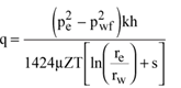
Because permeability and grain diameter are well connected, the production rate is generally less for small permeability values (e.g., less than 0.1 md), and flow is laminar near the crucial sandface.1,2 Well deliverability equations, developed from either an extension of oil production rate expressions or from fundamental principles, are well-known and used extensively.
In general, the production rate under laminar conditions is proportional to the pressure-squared difference between the reservoir pressure and the flowing BHP or, more appropriately, the difference between the real-gas pseudo-pressures.3
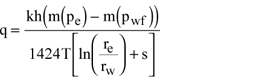
Equation 1 (see sidebar) describes the well production rate under a steady state, developed as an extension to the oil rate equation. Eq. 2 is based on the real-gas pseudo-pressure function. This function already incorporates the values of viscosity, µ, and the gas deviation factor, Z. Both Eqs. 1 and 2 can be cast either for pseudo-steady state or transient conditions by changing the function ln(re/rw) by ln(0.472re/rw) or pD, respectively. The driving pressure becomes,  , the average reservoir pressure, and pi, the initial pressure, respectively.3 , the average reservoir pressure, and pi, the initial pressure, respectively.3
| |
Well production rate under a steady state, Mcfgd
|
| |
 |
|
Eq. 1 |
| |
Real-gas, pseudo-pressure function
|
| |
 |
|
Eq. 2 |
|
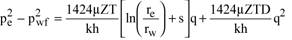
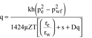
Turbulence effects have been studied by a number of investigators. Pioneer and prominent among these have been Katz and co-workers.4-6 In their work, they suggested that turbulence plays a considerable role in well performance, showing that the output rate is affected by itself – the larger the potential rate, the larger the relative detrimental impact would be. One interesting method by which one can account for turbulence was proposed by Swift and Kiel who presented Eq. 3, which, when rearranged, gives Eq. 4.7
Eq. 4 is significant, because it suggests that turbulence effects can be accounted for by a rate-dependent skin effect, where the turbulence (also referred to as the non-Darcy) coefficient, D, has the units of reciprocal rate. One of the implications is that, in testing a high-rate gas well, a calculated skin effect must be construed as apparent, rather then the real damage to skin. Procedures have been suggested for how to test gas wells, including multi-rate testing, the subsequent determination of apparent skins at each rate, the straight-line construction of s+Dq vs. q and the field-determination of both s, the vertical axis intercept, and, D, the slope.3
EFFECTS OF TURBULENCE IN RADIAL FLOW
Katz, et al., have presented an explicit relationship for radial gas flow into a well, using gas properties and by providing correlations for the turbulence coefficient,b, Eqs. 5 and 6.4 For an isotropic formation, k equals horizontal permeability. For the anisotropic formation, k is defined as the equivalent permeability, keq, where kV is the vertical, and kh is the horizontal permeability, Eq. 7.
| |
Turbulence effects
|
| |
 |
|
Eq. 3 |
| |
Turbulence as a rate-dependent skin effect
|
| |
 |
|
Eq. 4 |
|
Where:
D = Turbulence coefficient
s = Skin
|
|
Relationship for the radial flow of gas into a well
|
|
 |
Eq. 5 |
|
Where:
b = Turbulence coefficient, yielding
|
|
 |
Eq. 6 |
|
Anisotropic formation
|
|
 |
Eq. 7 |
|
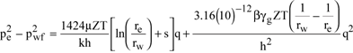
Various calculations have been performed using the Katz, et al., approach for a range of permeabilities. Table 1 contains the well and reservoir data used, and Table 2 presents the results. Table 2's first two columns show expected production rates for two flowing BHPs, for laminar and turbulent conditions, respectively, and for permeabilities from 1 to 100 md. At low permeability, as expected, rate reduction is negligible. However, at 100 md and pwf = 1,500 psi, the reduction is almost 50%. Turbulence effects, viewed as an apparent skin, result in values of 0.3, 1.2, 3.4 and 7.5, for 1, 5, 25 and 100 md, respectively (and pwf = 1,500 psi).
| |
Table 1. Well and reservoir characteristics |
|
| |
|
|
|
| |
| pe |
3,000 psi |
| re |
660 ft |
| rw |
0.359 ft |
| h |
50 ft |
| T |
710 °R |
| gg |
0.7 |
|
|
| Case 1 |
| pwf |
1,500 psi |
| m |
0.0162 cp |
| Z |
0.91 |
|
|
|
|
|
| |
| Case 2 |
| pwf |
2,500 psi |
| µ |
0.0186 |
| Z |
0.9 |
|
|
|
|
| |
Table 2. Turbulence effect at different permeability and drawdown |
|
| |
|
Case 1: pwf = 1,500 psi |
|
| |
|
q (b=0, s=0), |
q (b>0, s=0), |
q (b>0, s<0), |
|
| |
k, md |
MMcfgd |
MMcfgd |
MMcfgd |
|
| |
|
|
| |
1 |
3.0 |
2.9 |
8.1 |
|
| |
5 |
15.1 |
13.0 |
24.6 |
|
| |
25 |
75.3 |
51.9 |
71.7 |
|
| |
100 |
301.2 |
151.2 |
179.1 |
|
| |
|
|
|
|
|
| |
|
Case 2: pwf = 2,500 psi |
|
| |
|
q (b=0, s=0), |
q (b>0, s=0), |
q (b>0, s<0), |
|
| |
k, md |
MMcfgd |
MMcfgd |
MMcfgd |
|
| |
|
|
| |
1 |
1.1 |
1.1 |
3.7 |
|
| |
5 |
5.4 |
5.1 |
12.2 |
|
| |
25 |
27.0 |
23.0 |
37.9 |
|
| |
100 |
108.1 |
75.5 |
100.1 |
|
|
Because the 5- to 25-md range is the most likely to be encountered in emerging gas fields, the ratio of actual to ideal rates may be the most telling. For the two different drawdowns, these ratios are 0.86 and 0.95 (for the 5-md case) and 0.68 and 0.85 (for the 25-md case). When plotted, these results show the impact of the permeability value and the drawdown, Fig. 1. The ratio between turbulence-affected production, and the output calculated under assumption of laminar flow, declines precipitously as the reservoir permeability and drawdown increase and, hence, the output rate.
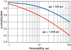 |
Fig. 1. Turbulence effect for a permeability range and different drawdowns.
|
|
An additional, interesting issue is the question of negative skin effect. This will become even more pronounced, when the expected production rate from hydraulic fracturing is presented. For now, the authors use a hypothetical negative skin effect that could result from (e.g.) matrix acidizing of carbonate rock. In Table 2, the listed negative skin effects are, in fact, those that result from fracturing. What will become apparent is that hydraulic fracturing in gas wells has a much larger impact than just the mere imposition of a negative skin effect. This is because of the extraordinary reduction of turbulence effects.
When the turbulence effects are insignificant, the negative skin effect's impact is very large. In the 1-md case, the production ratio between the negative skin ( – 5.7) and the zero skin is near 3. Conversely, when turbulence effects are great, as in the 100-md case, the production ratio between the negative skin ( – 3.7) and the zero skin is far less, e.g., 1.2.
PERFORATED, CASED WELL IN A HIGH-RATE RESERVOIR
The previous section deals with flow reduction in an open-hole well, and it could also be considered as a reasonable approximation for a slotted liner.
For a cemented, perforated well, in the absence of turbulence, a configuration skin effect can be envisioned. This can be added to the denominator of the deliverability relations. Karakas and Tariq have published a method to calculate this skin effect, which depends on perforation tunnel length, perforation diameter, phasing (degrees among adjoining planes of perforations) and, especially, perforation density, i.e., perforations per unit of net thickness, measured in “shots per foot” (SPF).8
They also quantified the effect of vertical-to-horizontal permeability anisotropy. Understandably, the lower the vertical permeability, the larger the skin effect value would be. Finally, they showed that if the perforation tunnel lengths end outside a damage zone, rather than inside it, the composite damage/ perforation skin effect is substantially reduced.
Using the Karakas/ Tariq model, one important conclusion is that in a permeability-isotropic formation, without near-well damage, but with four shots per foot of typical tunnel length and diameter, the perforation skin effect equals zero.8 This configuration may be construed as openhole equivalent.
Ichara used an approach similar to the Karakas/ Tariq model, constructing a numerical model for a perforated gas well and accounting for turbulence effects.9 He showed that perforations add an additional production impediment because of increased turbulence. Some of Ichara's results that show the impact of permeability anisotropy and perforation tunnel length are shown in Fig. 2. One observation is that long perforations are useful, helping a well with reasonable perforation density (4 SPF) achieve performance close to that of an open-hole well (still affected by turbulence). From Fig. 2, one can conclude that a gas well with 4 SPF and a typical, 8-in. tunnel length in a sandstone reservoir (kv/kh = 0.1) will perform at about 85% of an openhole well's level. Fig. 2 shows an unfavorable 0° perforation phasing.
 |
Fig. 2. Productivity ratio vs. perforation length for k v /k h = 0.01, 0.1, and 1.0 (after Ichara 9 ).
|
|
For an isotropic formation, Fig. 3 suggests that by improving perforation phasing to 90° and (especially) by increasing perforation density to 8 or even 12 SPF, the cased, perforated well can be an even better performer than its openhole cousin. This is because of the flow channels' penetration beyond the sand face. In short, high-perforation density of long-penetrating tunnels reduces turbulence. For example (Fig. 3), given an 8 SPF and 18-in. perforation tunnels, the performance would be about 10% greater than an openhole well.
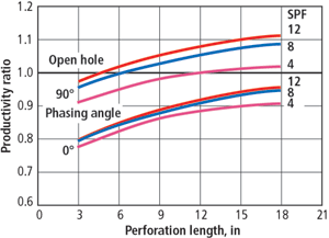 |
Fig. 3. Effect of shot density and phasing angle on productivity ratio for k v /k h = 1.0.
|
|
HYDRAULICALLY FRACTURED GAS WELL
Hydraulic fracturing has become the premier, production enhancement procedure. For the first 40 years since its inception, hydraulic fracturing has been used primarily for low-permeability reservoirs. However, in the last decade, its usage has expanded into medium- to high-permeability formations via the tip screenout (TSO) process. For gas wells, a reservoir above 0.5 md should be considered as a medium- to high-permeability formation (definitely above 5 md). In almost all such cases, the fracture should be a TSO treatment.10
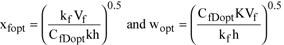
Valkó and Economides10,11 introduced a physical optimization technique to maximize the productivity index of a hydraulically fractured well. They have called this technique the Unified Fracture Design (UFD) approach. They also introduced the concept of the dimensionless Proppant Number, Nprop, Eq. 8. It is equal to the total volume injected, multiplied against the ratio of the net height to fracture height. They also found that for a given value of Nprop, there is an optimal, dimensionless fracture conductivity at which productivity is maximized.
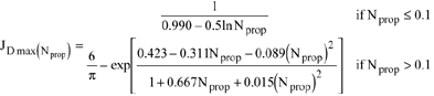
At “low” proppant numbers, optimal conductivity is expressed as CfD = 1.6. The absolute maximum for JD is 6/p = 1.909 (the productivity index for a perfect linear flow in a square reservoir). When the propped volume increases, or reservoir permeability decreases, the optimum, dimensionless fracture conductivity increases somewhat. (Note: In this article, for the fracture PI, we used the slightly different, pseudo-steady formulation rather than the steady-state formulation.)
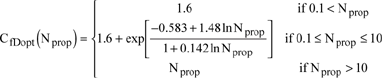
Valkó and Economides presented correlations for the maximum, achievable, dimensionless productivity index as a function of the proppant number, Eq.9. 10,11 Similarly, correlations were presented for the optimal, dimensionless fracture conductivity for the entire range of proppant numbers, Eq. 10. Once the conductivity is known, the optimal fracture length and width can be readily determined, Eq. 11.
In a potentially high-rate gas well, the important issue is that the effective proppant pack permeability (used to calculate the proppant number and dimensionless fracture conductivity) depends on the production rate, because of the non-Darcy flow effects. Economides, et al.12 presented an iterative procedure, combining the UFD method with the Gidley13 adjustment to the proppant pack permeability and the Cooke14 correlations for flow in fractures.
The procedure starts with the correction of effective permeability, using the in-situ Reynolds Number, Eq. 12. First, a Reynolds Number is assumed. Then, from Eq. 8 and using the adjusted proppant pack permeability, the proppant number is calculated. From this figure, the maximum J D (Eq. 9) and the optimum dimensionless conductivity (Eq. 10) are calculated. The latter allows determination of the indicated fracture dimensions, using Eq. 11.
From the dimensionless productivity index and the drawdown, actual production is calculated. This is used to obtain the Reynolds Number. The procedure ends when the assumed and calculated Reynolds Numbers are close enough. The Reynolds Number for non-Darcy flow is from Eq. 13. The value of b is obtained from Eq. 14. The velocity, v, is determined as the volumetric flow rate in the fracture, near the well, divided by the fracture height times the fracture width (both determined from the design in each iteration). For a detailed example, see Economides, et al.12
| |
Dimensionless Proppant Number, N prop
|
| |
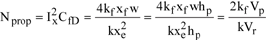 |
Eq. 8 |
| |
Where:
Ix = Penetration ratio
CfD = Dimensionless fracture conductivity
Vr = Reservoir drainage volume
Vp = Volume of proppant in the pay
|
|
Productivity index as a function of the proppant number
|
| |
 |
Eq. 9 |
|
Optimal, dimensionless fracture conductivity
|
|
|
|
 |
Eq. 10 |
|
Optimal fracture length and width
|
|
 |
Eq. 11 |
|
Where:
Vf = Volume of one propped wing, 
|
|
Correction of effective permeability, using the in-situ Reynolds Number:
|
|
 |
Eq. 12 |
|
Reynolds Number for non-Darcy flow:
|
|
 |
Eq. 13 |
|
Where:
kf,n = nominal permeability (Darcy flow) in m2
b = In 1/m
w = Fluid velocity at reservoir conditions, in m/s
µ = Fluid viscosity at reservoir conditions in Pa
r = Density of the flowing fluid in kg/m3
|
|
Value of b is obtained from:
|
|
 |
Eq. 14 |
|
Where:
a and b are obtained from Cooke14
|
|
Table 3 presents the results for the fracture designs and expected production rates for the four permeabilities already used for non-fractured wells, Table 2. These designs assumed sand as a proppant, with kf = 60,000 md.
| |
Table 3. Results from hydraulically fractured well (kf= 60,000 md) |
|
| |
|
|
Case 1: pwf = 1,500 psi |
|
| |
k, md |
s |
q, MMcfgd |
kf,e, md |
xf, ft |
|
| |
|
|
| |
1 |
–5.7 |
13.1 |
9,251 |
218 |
|
| |
5 |
–5.1 |
43.5 |
7,950 |
91 |
|
| |
25 |
–4.3 |
160.3 |
6,670 |
36 |
|
| |
100 |
–3.7 |
524 |
5,525 |
16 |
|
| |
|
|
|
|
|
|
| |
|
|
Case 2: pwf = 2,500 psi |
|
| |
k, md |
s |
q, MMcfgd |
kf,e, md |
xf, ft |
|
| |
|
|
| |
1 |
–5.7 |
5.8 |
12,493 |
250 |
|
| |
5 |
–5.1 |
18.9 |
10,770 |
108 |
|
| |
25 |
–4.3 |
69.2 |
8,980 |
44 |
|
| |
100 |
–3.7 |
224 |
7,494 |
20 |
|
|
There are important implications in comparing results in Tables 2 and 3. At 5 md, the non-fractured well would deliver 13 MMcfgd (with pwf = 1,500 psi). If the fracture-induced skin of – 5.1 is assumed, then production would be 24.6 MMcfgd, approximately a two-fold increase, Table 2. Such a production increase ratio would be expected in an oil well, flowing at laminar conditions. However, the implicit reduction in turbulence effects – because of the flow profile modification in going from converging radial flow to fracture flow – leads to a further, considerable increase in production to (in this example) 43.5 MMcfgd, a more-than-three-fold increase, Table 3. For higher permeability wells, the resulting folds are similar, albeit actual production rates achieved are spectacular, Fig. 4.
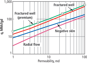 |
Fig. 4. A comparison of gas production rates from non-fractured wells, wells with negative skin and fractured wells.
|
|
Table 4 shows that if premium proppants are used (k f = 600,000 md), even more prolific fractured wells are achieved.15
| |
Table 4. Results from hydraulically fractured well (kf= 600,000 md) |
|
| |
|
|
Case 1: pwf = 1,500 psi |
|
| |
k, md |
s |
q, MMcfgd |
kf,e, md |
xf, ft |
|
| |
|
|
| |
1 |
–6.1 |
19.9 |
38,300 |
375 |
|
| |
5 |
–5.9 |
59.2 |
32,050 |
182 |
|
| |
25 |
–5.4 |
202 |
27,110 |
75 |
|
| |
100 |
–4.8 |
637 |
22,410 |
35 |
|
| |
|
|
|
|
|
|
| |
|
|
Case 2: pwf = 2,500 psi |
|
| |
k, md |
s |
q, MMcfgd |
kf,e, md |
xf, ft |
|
| |
|
|
| |
1 |
–6.1 |
8.8 |
51,600 |
456 |
|
| |
5 |
–5.9 |
26.3 |
44,150 |
211 |
|
| |
25 |
–5.4 |
88.4 |
37,020 |
91 |
|
| |
100 |
–4.8 |
270.0 |
31,720 |
41 |
|
|
CONCLUSIONS
Turbulence effects are the dominant features in the production of high-permeability (>5 md) gas wells. Turbulence may account for a 25%-to-50% reduction in the expected openhole production rate from such wells, if laminar flow is assumed. Cased, perforated wells may experience further turbulence-induced rate declines that can be alleviated somewhat with long-penetrating perforation tunnels and large perforation densities (e.g., 8 to 12 SPF).
However, nothing can compete with hydraulic fracturing. In higher-permeability gas wells, incremental benefits greatly exceed those of comparable-permeability oil wells. This is true, exactly because of the dramatic impact on reducing turbulence beyond the mere imposition of a negative skin. It is fair to say that any gas well above 5 md will be greatly handicapped, if not hydraulically fractured. Indeed, pushing the limits of hydraulic fracturing by using large quantities of premium proppants will lead to extraordinary production increases. 
LITERATURE CITED
1 Wang, X., “Pore-level modeling of gas-condensate flow in porous media, PhD Dissertation, University of Houston, May 2000.
2 Yao, C. Y., and S. A. Holditch, “Estimating permeability profiles using core and log data,” SPE Paper 26921, 1993.
3 Economides, M. J., A. D. Hill and C. A. Ehlig-Economides, Petroleum Production Systems, Prentice Hall, New York, 1994.
4 Katz, D.L., D. Cornell, R. Kobayashi, F. H. Poettmann, J. A. Vary, J. R. Ellenbaas, and C. F. Weinang, Handbook of Natural Gas Engineering, McGraw-Hill, New York, 1959.
5 Firoozabadi, A. and D. L. Katz, “An analysis of high-velocity gas flow through porous media,” JPT, February 1979.
6 Tek, M.R., K. H. Coats and D. L. Katz, “The effect of turbulence on flow of natural gas through porous reservoirs,” JPT, July 1962.
7 Swift, G.W. and O. G. Kiel, “The prediction of gas well performance including the effects of non-darcy flow,” JPT, July 1962.
8 Karakas, M. and S. Tariq, “Semi-analytical production models for perforated completions,” SPE Paper 18247, 1988.
9 Ichara, M. J., “The performance of perforated completions in gas reservoirs,” SPE Paper 16384, 1987.
10 Economides, M. J., R. E. Oligney and P. P. Valkó, Unified Fracture Design, Orsa Press, Houston, May 2002.
11 Romero, D.J., P. P. Valkó and M. J. Economides, “Optimization of the productivity index and the fracture geometry of a stimulated well with fracture face and choke skins,” SPE Paper 73758, 2002.
12 Economides, M.J., R. E. Oligney and P. P. Valkó, “Applying unified fracture design to natural gas wells,” World Oil, October 2002.
13 Gidley, J.L, “ A method for correcting dimensionless fracture conductivity for non-darcy flow effects,” SPE Paper 20710, 1990.
14 Cooke, C.E., Jr., “Conductivity of proppants in multiple layers,” JPT, September 1993.
15 Demarchos, A.S., A. S. Chomatas, M. J. Economides, J. M. Mach and D S. Wolcott, “Pushing the limits in hydraulic fracture design,” SPE Paper 86483, 2004.
THE AUTHORS
|
 |
Xiuli Wang is a production engineer with BP in Houston, working primarily with gas wells on the Outer Continental Shelf. She holds an MS degree from Tsinghua University and a PhD from the University of Houston, both in chemical engineering.
|
 |
Michael J. Economides is a professor at the Cullen College of Engineering, University of Houston, and the chief technology officer at the Texas Energy Center. Previously, he was the Samuel R. Noble professor of petroleum engineering at Texas A&M University, and he served as chief scientist at the Global Petroleum Research Institute. Prior to Texas A&M, Dr. Economides was director of the Institute of Drilling and Production at Austria's Leoben Mining University. Before that, he worked in a variety of senior technical and managerial positions with a major petroleum services company. His publications include authoring or co-authoring 11 professional textbooks and books, including The Color Of Oil and almost 200 journal papers and articles. In addition, he does a wide range of consulting, and he has had professional activities in over 70 countries.
|
| |
|
|

