Seismic Processing
Solutions for large-scale full-volume wave equation migration
A new migration technique allows generation of full-volume iterations during model building relatively quickly; small sacrifice in precision is more than compensated for by its ease, speed and cost-effectiveness
Denes Vigh and E. William Starr, Staag Imaging, L.P.; Danny Addis, Anadarko Petroleum Corp.
In the past decade, Gulf of Mexico exploration has been focused on uncovering hidden subsalt traps through depth migration techniques. Until recently, large-scale pre-SDM projects generally were based on the Kirchhoff algorithm. Most Kirchhoff traveltime calculations have difficulty reconstructing complex travel paths, especially in a subsalt environment. A few years ago, due to limitations in hardware systems, large-scale regional pre-SDM projects were generated on a grid-line basis with heavy decimation of both input and output data. These approaches, in conjunction with the limitations of Kirchhoff, were insufficient to image near irregular salt bodies.
Most 3D seismic data in the GOM are acquired with conventional multi-streamer vessel configurations. In these acquisition schemes, the line-offset component is relatively small compared to the inline component, making it easier to justify the use of common offset/ common azimuth (COCA) migration schemes. The speed of this migration technique facilitates the generation of full-volume iterations during model building in a relatively short time. Implementing true amplitude terms and illumination compensation ensures fast and accurate results for regional or detailed production studies in a cost effective manner.
In the past few years, several wave-equation migration (WEM) approaches have emerged. One of these algorithms is common offset/ common azimuth, double square root (DSR) migration that permits executing large projects reasonably fast. In addition to the migration algorithm's advantage in computational speed, angle gathers for velocity model building can be generated as part of the process. Since this technique outputs full volumes, interpreters have the advantage of working on complete cubes, as opposed to a sparse grid of target lines to determine the top and base of salt, and even more toward interpretation of salt overhangs. The flexibility and speed of the COCA algorithm allows full-volume WEM imaging of large-scale regional depth projects in a timely fashion.
ALGORITHM DESCRIPTION
The common-azimuth migration is based on a downward-continuation operator derived from the DSR equation. The task is accomplished by downward continuing all sources and receivers at each step. Therefore, the basic downward continuation is performed by the following equation:
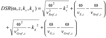
Where vS,z and vG,z are velocities for the source and receiver
positions and vSref,z and vGref,z are the set of reference velocities for every depth step. Depending on the complexity of the velocity regime, the number of reference velocities may significantly influence image quality.
At each depth level, the image is extracted from the wavefield by application of an imaging condition. The imaging condition is achieved by evaluation of the wavefield at zero time (summation over all frequencies) and zero offset (summation over offset wavenumbers) as:
For given field-acquisition parameters, true amplitude corrections and illumination compensation are incorporated to achieve the best possible image. Amplitude corrections are applied to the migration operator, whereas the illumination balancing is intended to compensate for anomalous amplitude variations induced by the convolution of the acquisition scheme and the geologic model.
The true amplitude correction includes the application of the WKJB approximation (Clayton and Stolt):
and the diagonal operator of the imaging Jacobian. For the angle gathers, the dispersion relation used to downward continue the wavefield is given by the DSR equation:
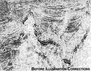
The illumination correction is calculated independently from the seismic data and a reference image. The only common ground is the velocity model used to migrate the seismic data and model/ remigrate the reference image. The reference image consists of monochromatic flat events. The ratio between the reference image and the modeled and remigrated image is the weight function applied to the seismic data to create the final normalized migrated volume. The correction volume is calculated prestack, which can be viewed either in angle-gather mode (Fig. 1) or common angle domain (Fig. 2). Figs. 3a and 3b show a comparison of 3D data imaged with and without the illumination correction applied.
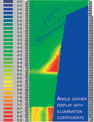 |
Fig. 1.The correction volume is calculated prestack, viewed here in angle-gather mode.
|
|
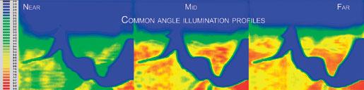 |
Fig. 2. The correction volume is calculated prestack, viewed here in common angle domain.
|
|
 |
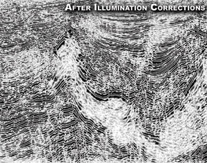 |
Fig. 3. Comparison of 3D data imaged with and without the illumination correction applied.
|
|
VELOCITY MODEL BUILDING
The outputs of the migration process are image gathers in the angle domain that are used along with velocity updates to create the intermediate and/or the final images with illumination correction.
The migration has the following capabilities:
- Frequency controlled migration with flexible QC prior to or during the migration
- Multiple reference velocities allow optimization in zones of rapid lateral velocity variation
- True amplitude compensation
- Illumination compensation.
Although the migration may be straightforward, the preconditioning cannot be forgotten. Creating common offsets with evenly populated bins across the survey is very important for this method. Amplitude control within and across the offset planes is essential to the success of the final migration results.
Velocity model building comprises the following steps:
- Sediment field determination
- Salt geometry definition
- Subsalt update
- Model validation.
For the sediment-velocity field, angle gathers are used to pick residual interval velocities using a vertical update. When migrated with the correct velocity, data will be migrated to zero offset and angle gathers will exhibit no moveout. However, if the data is migrated with the wrong velocity, then residual energy will exist around zero-offset and angle gathers will curve either upward or downward. If the data is migrated with a velocity that is higher than the true velocity, then the result will be over-migrated and the apparent moveout for an event will be downward with increasing ray parameter. If the data is migrated with a velocity that is lower than the correct velocity, then the result will be under-migrated and the apparent moveout will be upward with increasing ray parameter, Fig. 4.
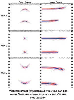 |
Fig. 4. When migrated, data offset and angle gathers might exhibit moveout effects (smiles and frowns) unless the data is migrated with the correct velocity.
|
|
The advantage of the COCA migration technique is that, besides the gathers, the full-volume image is available to assist in the interpretation of the velocities. The final sediment velocity field is arrived at after several iterations of vertical or tomographic updates. This is followed by salt geometry determination using the entire volume for the top and the base of salt interpretation giving the interpreter a better understanding of the complexity of both the top and base of salt.
Subsalt updates are done through angle gather velocity analysis concentrating on areas of sediment mini-basins to determine the interval velocity trend under the salt. Base of salt and final sediment velocity model are validated before the final migration, providing the interpreter the opportunity to review the salt-geometry and the subsalt velocities in conjunction with the illumination volume. During the model building, speed is a function of the survey size, depth step, max depth, number of offsets and number of frequencies used to build the image. Optimizing the above parameters for each of the model building steps can shorten the turnaround time on large regional projects. Common image angle gathers as the output of the migration can be used to carry out prestack AVA inversion, which is used in the exploration community to discriminate between fluid and lithology effects.
CONCLUSIONS
Common offset/common angle migration imaging provides a unified framework for constructing a wide range of wave equation migration results in a short space of time. This technique has been successfully used in various ways, from large regional studies to prospect generation, where turnaround time was an issue. In addition, the common angle image gathers produced by this method serve as input for the velocity analysis, amplitude versus angle studies and generation of pore pressure volumes, Fig. 5. 
 |
Fig. 5. Regional migrated volume with velocity model showing salt bodies.
|
|
ACKNOWLEDGMENT
We thank Anadarko Petroleum Corp. for permission to show the data examples, and Joan Myskowski of Staag Imaging, L.P. for her editing efforts and finalization of this abstract.
LITERATURE CITED
Biondi, B., and Palacharla, G., 1996, “3-D prestack migration of common-azimuth data,” Geophysics, Vol. 61, No. 6, pp. 1822 – 1832.
Clayton, R.W., and Stolt, R.H., 1981, “A Born-WKBJ inversion method for acoustic reflection data,” Geophysics, Vol. 46, No. 11, pp. 1559 – 1567.
Gazdag, J., and Sguazzero, P., 1984, “Migration of seismic data by phase shift plus interpolation,” Geophysics, Vol. 49, pp. 124 – 131
Kessinger, W., 1992, “Extended split-step Fourier migration: Expanded Abstracts of the Technical Program,” SEG 62nd Annual Meeting, 1992, pp. 917 – 920.
Popovici, A., 1996, “Prestack migration by split-step DSR,” Geophysics, Vol. 61, No. 5, pp. 1412 – 1416.
Prucha, M., Biondi, B., and Symes, W., 1999, “Angle-domain common-image gathers by wave-equation migration,” SEG 69th Annual Meeting, 1999, pp. 824 – 827.
Sava, P., Biondi, B. and Fomel, S., 2001, “Amplitude-preserved common image gathers by wave-equation migration,” 71st Ann. Internat. Mtg: Soc. of Expl. Geophys., 2001, pp. 296 – 299.
Ottolini, R., and Claerbout, J. F., 1984, The migration of common-midpoint slant stacks: Geophysics, Soc. of Expl. Geophys., Vol. 49, pp. 237 – 249.
THE AUTHORS
|
 |
Denes Vigh earned his MS in geophysics in 1983 at the Technical University in Hungary. He has 20 years of experience in operations with various seismic contractors including Paradigm Geophysical, CGG and Geco-Prakla. Mr. Vigh presently serves as Vice President of Operations at Staag Imaging.
|
 |
William Starr is well known in the industry as a geophysical software developer and, especially, for his role as the architect and main developer of the initial seismic data processing system named SeisUP (trademark). He presently leads the seismic software group as Vice President of Research and Development.
|
| |
Danny Addis is the Sr. Staff Geophysicist at Anadarko Petroleum Corp.
|
|