Artificial Lift
What's new in artificial lift
Part 1 – Fifteen new systems for beam, progressing-cavity, plunger-lift pumping and gas lift
James F. Lea and Herald W. Winkler, Texas Tech University, Lubbock, Texas; and Robert E. Snyder, Executive Engineering Editor
Described here are 15 recent developments in four categories of artificial lift technology, including: beam pumping (eight items); progressing-cavity pumping (PCP) (four); plunger lift (two); and gas lift (one). Part 2, coming in the May issue, will present electrical submersible pumping (ESP) and other, miscellaneous, artificial-lift-related innovations.
Beam pumping – by far the most widely used type of artificial lift – comprises a motor-driven surface system lifting sucker rods within the tubing string to operate a downhole reciprocating pump. PCP systems are based on a surface drive rotating a rod string which, in turn, drives a downhole pump rotor operating within an elastomeric stator.
In plunger lift, a freely moving plunger falls through fluids in the tubing and is lifted back to surface with its slug of mostly liquids by formation, or injected, gas admitted from the tubing-casing annulus. Gas lift systems inject gas from the casing-tubing annulus through valves into liquids in the tubing to reduce their density and move them to the surface.
BEAM PUMPING
The eight new techniques/ products for improving beam/ sucker-rod pumping feature new equipment for: a polished rod-mounted dynamometer; a plunger cleaning system; improved pump-off control software; a stuffing box with renewable “stuffing”; an online design/ performance calculator and a downhole gas separator design calculator; diagnostic software for optimizing artificial lift wells; a polished rod with two different pin ends; and a self-contained, remotely monitored rod pump controller.
Wireless qualitative dynamometer. Until now, producers, operators and service companies have had few alternatives to expensive, complicated dynamometers. In cases where a quick, qualitative operational dynamometer card is all that is needed, technicians have had no choice but to use full-featured quantitative dynamometer systems that were intended for pumping system design analysis.
D-Jax Corp., of Midland, Texas, now has an alternative to quantitative dynamometer systems. The D-Jax, E Z Draw, a qualitative, wireless electronic dynamometer, is installed on the polished rod in a matter of seconds without separating the clamp from the carrier bar, Fig. 1. The system interfaces through a portable computer and has valve check capabilities. Acquisition costs are a fraction of those for quantitative dynamometers.
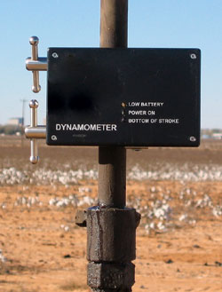 |
Fig. 1. Qualitative, wireless dynamometer installed on polished rod without separating clamp from carrier bar.
|
|
Cyclone plunger. From Eagle Innovation Inc., St. George, Utah, the Cyclone Plunger mounted directly above the conventional plunger allows sand, grit, iron sulfide and other fines which normally contaminate the produced oil and water to quickly pass though the pump assembly preventing their collection between barrel and plunger.
Clearance between conventional pump plungers and barrels permit some fluid bypass, in which these contaminates can accumulate. During normal up and down plunger motions, they cause rapid wear, usually vertical scoring, to both plunger and barrel surfaces. And frictional forces generated often result in a stuck pump, automatic shut-down of the pumping unit, or a parted rod string.
With the new plunger component, during the downstroke, it forces any entrained particulates collected within the space between barrel and plunger inwardly through the evacuation ports and into the center of the plunger, Fig. 2. There, they commingle with other fluids entering the pump and are displaced into the tubing. Throughout the upstroke, particulates are also collected within the tapered neck of the new plunger, where, during the downstroke, they are flushed upward and enter the tubing through the three-wing case.
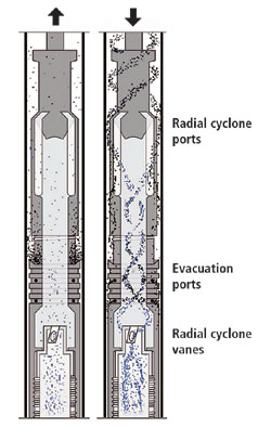 |
Fig. 2. Cyclone Plunger mounted above regular sucker rod plunger removes contaminates and particles from cylinder wall and forces them into the main flow stream into the tubing string.
|
|
Simultaneously with the above actions, the axial ported-vane technology incorporated within the new system causes the fluid-particulates to constantly rotate. This permits the pump barrel and plunger to wear more evenly, resulting in longer pump life and more cost-efficient pump assembly.
Improved well automation software. The XSPOC software from Theta Enterprises, Brea, California, offers advanced well automation capabilities for the oil field. While the product has been available for several years, recent enhancements have made it more powerful. The new system uses artificial intelligence to not only monitor, but also perform detailed analysis of rod pumping systems; and it is the only automation package to offer the developer's XDIAG diagnostics module. This module uses pattern recognition and complex logic algorithms to arrive at accurate conclusions about the performance of rod-pumped wells.
Users report that the software is easy to use, making this system effective for the novice. Many of the screens within the system are fully configurable, so that users can tailor the look and feel to their needs. One of the new system additions is an enhanced call-out capability that allows it to automatically alert an operator about a well problem by telephone, cell phone or pager.
The software is also built on an entirely open Microsoft database, so the information is easily accessible with other tools. This also allows it to be easily integrated with other data systems that may already be in use. An example output would include: plots of load vs. position, Fig. 3, plus tabular data such as: 1) the card library with date/time; 2) input, e.g., run time, SPM, pump depth, etc.; 3) output, e.g., DH stroke/ capacity, pump efficiency, rod weight, etc.; and 4) analysis data (results).
 |
Fig. 3. Example output data from well automation software application.
|
|
As a testimony to the software's power/ capabilities, it is being used in one of the largest pump-off control (POC) installations in the world (Belridge field, California) to manage over 4,000 wells. The system has numerous large installations in California, West Texas and Canada. More recently, it has been used in coalbed methane projects where rod pumps are used for dewatering.
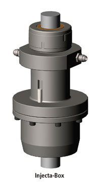 |
Fig. 4. Stuffing box that allows renewable “stuffing” to be injected.
|
|
Renewable stuffing box. Harbison-Fischer (H-F), Fort Worth, Texas, has developed and patented the revolutionary Injecta-Box stuffing box utilizing a concept that allows the operator to inject renewable “stuffing” into the stuffing box without opening it. This new design can be used on sucker rod pumping wells or PCP wells, Fig. 4.
The injectable sealant is a pressure-actuated, user-friendly sealing material that is robust and long-lasting. It has been used in the rotating shaft sealing industry for years and has now been field tested and optimized for use as a linear polished rod seal. An internal, tubing-pressure-actuated piston maintains pressure on the sealant to keep it formed around the polished rod or liner as it is consumed. Indicator pins are visible from the outside showing the amount of remaining packing.
The new stuffing box is only available for use with the H-F Pro-Align polished rod alignment tool in sizes for 1-1/8- , 1-1/4- and 1-1/2 -in. polished rods and liners. Options that can be added are the patented Flap-Tite, which seals off if a polished rod breaks; and the Enviro-Guard, an additional stuffing box with a pressure monitoring port for environmentally sensitive areas.
Two artificial lift online calculators. Echometer Co., Wichita Falls, Texas, has added two artificial lift, online calculators to the Internet. The first addition, QRod-Web, is the most widely used, free program – total downloads to date 2,153 – for design/ prediction of performance of sucker rod beam pumping installations. The objective is to help the beam pumping system designer implement state-of-the-art design technology without getting buried with details. The program uses a wave equation solution to accurately predict surface dynamometer loads, gearbox torque and plunger velocity, based on a minimum of user inputs.
 |
Fig. 5. Example output from a QRod-Web analysis.
|
|
The effect of changing a parameter such as tubing anchor, stroke length, stroke rate or pump diameter can be immediately seen in the dynamically updated plots. Output of the program, Fig. 5, includes pump displacement, rod string loading, surface unit and motor size requirements for any input depth and design production rate. User inputs include choice of surface unit geometry such as conventional, Mark, Reverse Mark or air-balanced units. And tapered steel rod strings (API taper) and fiberglass/ steel combination strings are allowed.
The second online calculator, the new downhole gas separator design calculator, Separator Design, allows an operator to describe expected flow conditions at the pump; then, automatically, the calculator properly sizes a gas separator for the specified well conditions. The calculator includes the effect of pump intake pressure and annular gas/liquid flowrates on separation efficiencies, in combination with the wellbore's tubing and casing sizes.
Acquisition/diagnostic software. The newly released Version 2.0 of Echometer's TWM (Total Well Management) data acquisition and diagnostic software for optimization of artificial lift wells has been extensively modified to offer numerous new features and utilities. This can provide the most advanced program for acquisition/ integration of acoustic fluid level, dynamometer, motor power and well pressure data.
With this new software, the user can immediately analyze well site conditions with unlimited acquisition of dynamometer data, from two strokes to several hours. This feature allows monitoring rod pump performance and detecting onset of pump-off and erratic operation. It also facilitates setting limits on POCs and timers.
Data input screens have been added to allow entry of descriptive ESP equipment information on all components in a well. This enhancement of using the TWM database to maintain information on installed equipment provides the ability to manage ESP inventory and allows the tracking of well performance as a function of operational/ pumping system changes. Other features of the new software include:
- A new worksheet to calculate pump intake pressure (PIP) using the fluid load from the pump card, Fig. 6. This allows determination of unaccounted friction due to stuffing box and/or other effects. Different options provide the flexibility to calculate accurate PIP using fluid load from a downhole pump card.
- A Recommendation Summary Report can be created in MS Word format, summarizing well data and containing any recommendations written about the well, for transmittal to company personnel without using TWM.
- Any data in the TWM database can be selected and exported in spreadsheet format. This provides the capability to: 1) upload and update corporate databases; 2) update spread sheets with a totally user-defined format; and 3) generate historical tables and graphs with minimal user input.
 |
Fig. 6. Pump intake pressure calculated using fluid load from pump card.
|
|
And the system has advanced reporting features such as multi-well and multi-test report generation, as well as automatic printing of summary reports of well data acquired over any period of time.
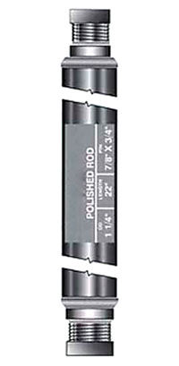 |
Fig. 7. New polished rod design with different pin sizes on each end.
|
|
Dual-pin polished rod. The TWIN PIN Polished Rod from Hasco Manufacturing Co., Sapulpa, Oklahoma, features a different size API thread on each end, Fig. 7. This is an added value and convenience, at no additional cost. Principal benefits are that the newly designed system saves up to one-half the inventory costs and floor space required to warehouse polished rods. And it eliminates confusion in the field regarding which thread size is needed for each well, and associated costs when the wrong pin size is delivered.
Users can identify inventory using the developer's color code which identifies size of both the API polished rod and the two different pins. Use of the color code saves time, physical labor and the frustration of trying to identify a polished rod by wrestling it to find its label. Further, the new-design polished rods cost the same as regular PRs. This allows oilfield suppliers to maintain current sales with only half the inventory investment.
Self-contained rod pump controller. Rod pump controllers (RPCs) have been documented to cut electrical costs, reduce repair costs and increase production. Unfortunately, most operators are reluctant to install them on low-production wells because of the capital, installation and maintenance costs.
Now through a unique, self-contained design, eProduction Solutions of Houston has created iBEAM , the only RPC that uses advanced load and position technology, but does not require the cabling and trenching associated with most RPCs. Because of its cableless design, it is able to eliminate wear/ damage repairs associated with cables to the load cell and position sensor. Fig. 8 shows how the system is mounted on the unit's I beam.
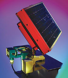 |
Fig. 8. Rod pump controller mounted on walking beam communicates to well control box with radio technology.
|
|
The new system uses advanced load and position technology recognized as the most effective way to control rod pumped wells. Using the latest strain gauge technology for load measurement, and an electronic accelerometer for position, the controller creates a dynamometer card that identifies pump off and other potential problems.
Rather than running a signal cable from the pumping unit to the control box, a radio communicates with the well's control box. This provides starting and stopping capabilities. The radio technology is also used to relay operational data to a host-based system for remote monitoring and detailed analysis.
The new system contains the same load and position technology that has been field proven on more than 25,000 wells around the world. Its design eliminates or reduces much of the installation, maintenance and unit costs typically associated with RPCs.
PROGRESSING CAVITY PUMPING
Four PCP advances from three companies include: an insertable PCP; a heavy-duty drive head; a multiple-lip drive head seal; and a high-torque sucker rod and coupling.
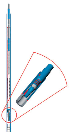 |
Fig. 9. Insertable PCP system can be installed in 2-7/8 -in. to 5-in. strings without pulling the tubing.
|
|
Insertable PCP system. The new Moyno Insertable Progressing Cavity (IPC) Pump System from R&M Energy Systems, Houston, is engineered to allow downhole PCP installation and retrieval without having to pull the production tubing, Fig. 9. This considerably reduces time/ pulling costs. In addition, it provides high operational reliability/ flexibility, reducing overall life cycle costs compared to other artificial lift systems. These systems can handle a wide range of conditions, including low- and high-viscosity fluids and solids transport. They have been engineered for strong performance in oilfield and coalbed methane dewatering applications.
Other benefits of the IPC pump systems include: 1) unique hold-down devices that provide tubing-pump annulus sealing at pump intake, and accurate installation at seating assembly; 2) easy rotor-tag spacing without retrieving pump from the locked position; 3) system allows flushing operations without disengaging pump from seated position; 4) the landing nipple is the only system component attached to the tubing string at the bottom of the hole; and 5) the system is ideal for quick, inexpensive pump changes, allowing the user to match well conditions in terms of differential pressure and/or flow without retrieving the tubing string.
The new IPC pumps can be installed in 2-7/8 -in.- to 5-1/2 -in.-diameter tubing. In the interest of installation time, it is recommended that all production tubing and components, through which the insertable must pass, be drifted to prevent any problems. No special tools are required for installation.
Heavy duty drive head. The new Moyno Ultra-Drive Model EX1 Surface Drive Head from R&M Energy Systems is designed for use with Moyno downhole PCPs in applications that require larger pump sizes and/or extraction from deeper wells. This new unit offers rugged construction and improved operational features for heavy-duty downhole PCP applications. It offers easy installation, safe/ consistent recoil control during shutdown, and improved dynamic wellhead sealing capability.
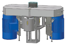 |
Fig. 10. Heavy duty PCP drive head designed for applications requiring larger pump sizes and/or production from deeper wells.
|
|
The system's motor support frame is designed to accept dual electric motors in horsepower ranges from 50 to 150 (maximum 300 hp with both motors installed) with maximum polished rod speed of 600 rpm and operational polished rod torque of 4,000 ft-lb, Fig. 10. Weight of rod string and rotary PC pump thrust load is supported by the axial thrust bearing in the heavy-duty gearbox.
Dynamic load rating of the standard bearing is 80,369 lb, based on a CA90 rating. The gearbox assembly contains a spiral bevel gear set, directly linked to a hydraulic motor drive. In the backspin mode, normally resulting from release of energy stored in the well at shutdown, this hydraulic motor drive retards rotational speed for effective, safe control.
The low profile design simplifies field mounting and installation, and a removable sealing system makes it versatile and ensures easy maintenance. It can accommodate polished rod sizes between 1-1/2 in. and 2-1/16 in.
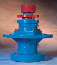 |
Fig. 11. Rotary drive head seal for PCP systems.
|
|
Drive head seal for PCPs. The new Rotary Seal Unit (RSU) from Baker Hughes Centrilift, Claremore, Oklahoma, is the latest component to complement the LIFTEQ LT Drivehead Series for PCP Systems, Fig. 11. It is a unique sealing system rated for operation to 550°F (288°C), with redundant leak prevention features, and is approved for use with LIFTEQ LT30E, LT50E, LT100E, LT150E and LT300E drive heads.
The new seal utilizes multiple lip seals as a primary seal, and a secondary seal area that includes conventional Teflon and graphite rope-style packing. The system provides an early warning in advance of a primary seal failure and, as such, the secondary seal can be easily engaged to avoid an unscheduled pumping system shutdown. The secondary sealing system operates as a conventional stuffing box and can continue to be utilized until maintenance can be scheduled, thus avoiding costly additional shut downs.
An added benefit of the RSU is reduced polished rod wear. The primary seals are designed so that, while in operation, polished rod wear is reduced or eliminated. The Centrilift RSU can also be adapted to other manufacturers' products.
High-torque rod and coupling. Weatherford, Edmonton, Alberta, Canada, has developed larger PCPs and top drives to meet industry's artificial lift needs. As these two components increase in size, torque on the sucker rod used to join the top drive and PC pump has increased as well. Traditionally, the approach has been to make a larger sucker rod; however, this restricts fluid flow and increases both string weight and torque, requiring larger, more expensive top drives.
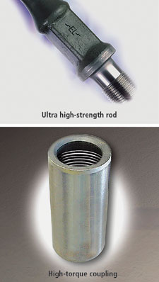 |
Fig. 12. High strength PCP sucker rod (a), and high-torque rod coupling (b).
|
|
To address these applications, Weatherford's proprietary ultra high-strength sucker rod proves a viable solution. The EL rod is capable of handling high torques of new top drives and PC pumps. To further enhance the rod's high torque rating, the high-torque (Hi-T) coupling was developed, Fig. 12. This coupling has pushed the new rod's torque rating, with a built-in service factor beyond industry's traditional thresholds. Because of this built-in safety factor, there is no need to decrease the new rod's published torque rating as is done with conventional rods.
The ultra-high torque ratings of the new rod and coupling typically allow the operator to drop down one size, e.g., 7/8 -in., vs. 1-in. conventional. This gives a lighter string weight, larger flow areas and lower torques. In addition, the new rod can also have centralizers when required, unlike larger sucker rods.
PLUNGER LIFT
Two recently introduced advances in plunger-lift technology include: a high-speed, continuous-flow plunger offering increased travel speed, both up and down; and a new plunger design with improved sealing pads and bypass system.
Continuous-flow plunger. The recently introduced RapidFlo plunger, from Weatherford, Houston, is a high-speed, continuous-flow plunger designed for maximum flow-through while still maintaining strength in material. This plunger, when applied properly, will fall against flow to the bottom of the well, reset, then return to surface using only velocity of the flowing gas to form a seal to deliver fluid without any shut-in time.
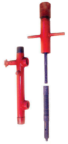 |
Fig. 13. High-speed, continuous-flow plunger system.
|
|
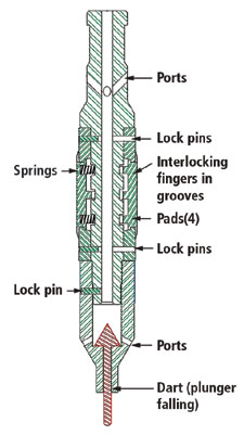 |
Fig. 14. Improved sealing and rapid fallback features on new plunger design.
|
|
The largest advantage for operators is reduced downtime due to the increased speed of travel (both up and down), which results in the maximum number of trips per day. With fewer moving parts, the new plunger can travel with minimal fluid loads without causing damage, Fig. 13. Overall simplicity of the single-piece design makes the tool easy to operate and inspect. Additional benefits include: the solid-ring design, large internal flow path, floating valve design, internal fish neck and the ability to operate in standard installations.
The new plunger is particularly effective in low-line-pressure/ high-velocity applications, especially in single-well compression where downtime can be critical to compressor operation. Additional applications include high liquid producing wells that require numerous trips to move the fluid, and wells that are just beginning to liquid load. It also works well in winter conditions, where continually moving plungers can minimize hydration problems.
Optimum-seal plunger. Compared to other plungers which either allow large amounts of gas to flow past the outer sealing areas or have slow fall times, the patented Opti-Seal-Quick Trip Plunger from Opti-Flow, LLC, Spring, Texas, allows for the optimum seal on its trip to the surface and quick fall time to bottom, Fig. 14. Combination of these two features will provide more efficient operations, improved travel times and increased production.
The sealing plunger comes with a unique large bypass for quick fall times. Patented interlocking pad fingers provide the optimized seal, as gas flow trapped underneath the pads keeps them against the tubing wall, creating the seal between gas below the plunger and liquid above.
The patented bypass system allows the plunger to fall to bottom at a faster rate, incorporating a dart that goes on seat when the plunger falls to the bottom stop. Differential pressure from below causes the dart to stay on seat on its trip to surface; no springs, balls or O-rings are required. When the well is shut in, the dart comes off seat, allowing flow through the bypass for quick fall time. Made of corrosion resistant 17-4 materials for CO 2 and H 2 S service, no elastomers are present. Pads are heat treated and hardened for extended life.
GAS LIFT
One gas-lift innovation that has been recently introduced is shown here – a new high-pressure valve that allows operation of deeper, higher pressure gas lift wells.
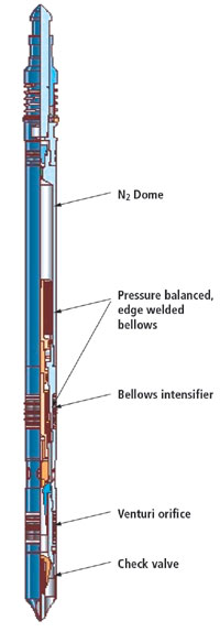 |
Fig. 15. High-pressure gas-lift valve system for deeper wells, both onshore and offshore.
|
|
High-pressure gas lift system. The new proprietary XLift high-pressure gas lift system from Schlumberger, Houston, Fig. 15, extends the capability of present gas lift systems by increasing the range of operating pressures to 5,000 psi from 2,000 psi. Improving on field-proven Camco gas lift technology, this new system enables completion of high-pressure gas lift wells and operation with higher injection pressures and deeper injection points to increase well performance. With higher operating pressure, wells can be completed with fewer mandrels and valves, making the new valve the system of choice for deepwater and subsea gas lift.
To accommodate higher operating pressure, the 1-3/4 -in. valve incorporates an innovative edge-welded bellows system. Manufactured using corrosion-resistant materials, this new bellows reduces the internal gas charge while increasing operating injection pressure. During offshore operations, this allows the operator to inject high-pressure gas below the mudline and significantly improve depth of injection required to maximize drawdown and increase production.
The new valve is subsurface-controlled, with no physical linkage to surface. It features a venturi flow configuration for more efficient and stable gas throughput, and a positive check valve that eliminates potential leak paths to the casing/ tubing annulus. A larger 1-3/4 -in. OD improves the valves' geometry, resulting in improved performance. The venturi flow system with dual-bellows control is incorporated into the valve, mounted in the polished bore receptacle of the side pocket mandrel to form a single lift station.
Designed using proven retrievable gas lift and flow control valve (FCV) equipment technology, this innovative high-pressure system consists of a gas lift valve, valve latch, side pocket mandrel, and associated kickover tool with running and pulling tools. 
THE AUTHORS
|
 |
James F. Lea, professor, chairman of Petroleum Engineering, Texas Tech University, Lubbock, holds BS/MS degrees in ME from the University of Arkansas, and a PhD in ME from Southern Methodist University. He worked for Sun Oil Co. as a research engineer from 1970 to 1975; from 1975 to 1978, he taught engineering at the University of Arkansas; and from 1979 to 1999, he was leader of optimization and artificial lift at Amoco EPTG. He assumed his present position in 1999. Mr. Lea is a registered professional engineer in Texas; he has authored/ co-authored several patents, as well as publications on artificial lift.
|
 |
Herald W. Winkler is former chairman, now professor emeritus and research associate, in the Department of Petroleum Engineering at Texas Tech University in Lubbock, Texas. He is presently working as a consultant in artificial lift, specializing in gas lift.
|
| |
|
|
 Part 2 Part 2 |
|

